Apr 13, 2011 - Pavement Repair Materials. Lucy P. Priddy. Geotechnical and Structures Laboratory. U.S. Army Engineer Research and Development Center.
ERDC/GSL TR-11-13
Development of Laboratory Testing Criteria for Evaluating Cementitious, Rapid-Setting Pavement Repair Materials
Geotechnical and Structures Laboratory
Lucy P. Priddy
Approved for public release; distribution is unlimited.
April 2011
ERDC/GSL TR-11-13 April 2011
Development of Laboratory Testing Criteria for Evaluating Cementitious, Rapid-Setting Pavement Repair Materials Lucy P. Priddy Geotechnical and Structures Laboratory U.S. Army Engineer Research and Development Center 3909 Halls Ferry Road Vicksburg, MS 39180-6199
Final report Approved for public release; distribution is unlimited.
Prepared for
Headquarters, Air Force Civil Engineer Support Agency Tyndall Air Force Base, FL 32403-5319
ERDC/GSL TR-11-13
Abstract: Numerous commercial-off-the-shelf products are available for small surface repairs in portland cement concrete (PCC) pavements that provide short set times, high early strengths, and durability to withstand heavy loads. Investigations of pavement repair materials conducted at the U.S. Army Engineer Research and Development Center (ERDC) in Vicksburg, MS, and other test organizations examined cementitious rapidsetting repair materials for repair of PCC pavements through laboratory and field characterization. Standard laboratory tests were performed to characterize the material properties over time and to provide a mechanism for assessing the material suitability for field repairs. Numerous repairs were constructed and evaluated under controlled traffic conditions to determine the ability of the repairs to support aircraft traffic after a minimum curing period. A laboratory protocol was developed for selection of cementitious, rapid-setting repair materials based on the laboratory and full-scale test results. This protocol originally developed in 2006, aided airfield managers and repair teams by reducing the potential for selection of materials that were likely to perform poorly. Changes to the protocol were made based on a review of material properties and field performance of materials tested at ERDC and other test agencies to improve the process of selecting materials based on repair type and size.
DISCLAIMER: The contents of this report are not to be used for advertising, publication, or promotional purposes. Citation of trade names does not constitute an official endorsement or approval of the use of such commercial products. All product names and trademarks cited are the property of their respective owners. The findings of this report are not to be construed as an official Department of the Army position unless so designated by other authorized documents. DESTROY THIS REPORT WHEN NO LONGER NEEDED. DO NOT RETURN IT TO THE ORIGINATOR.
ii
ERDC/GSL TR-11-13
Contents Figures and Tables .........................................................................................................................................v Preface ............................................................................................................................................................vi Unit Conversion Factors .............................................................................................................................vii 1
Introduction ............................................................................................................................................ 1 Problem statement ................................................................................................................... 1 Objective and research approach ........................................................................................... 3 Outline of chapters ................................................................................................................... 3
2
Background ............................................................................................................................................ 4 Rapid-setting material options ................................................................................................ 4 Ultrafine portland cement............................................................................................................ 5 Magnesium phosphate ................................................................................................................ 6 High alumina ................................................................................................................................ 6
Repair material requirements ................................................................................................. 6 Development of draft laboratory test criteria ......................................................................... 7 Selected material investigations ............................................................................................. 8 Laboratory tests 2006-2008 ....................................................................................................... 8 Material testing 2008-2009 ...................................................................................................... 14
Laboratory tests 2009-2010 ................................................................................................. 17 Shortfalls of previous research ............................................................................................. 19 3
Cementitious Material Laboratory Test Descriptions..................................................................21 Strength .................................................................................................................................. 21 Compressive strength ................................................................................................................ 21 Flexural strength ........................................................................................................................ 21
Bond strength ......................................................................................................................... 22 Time of setting ........................................................................................................................ 24 Shrinkage ................................................................................................................................ 25 Modulus of elasticity .............................................................................................................. 27 Volumetric expansion or contraction..................................................................................... 28 Coefficient of thermal expansion .............................................................................................. 28 Length change............................................................................................................................ 28
Methods of curing and capping ............................................................................................. 29 Curing .......................................................................................................................................... 29 Capping ....................................................................................................................................... 29
Replicates ............................................................................................................................... 30 4
Results and Discussion......................................................................................................................31 Compressive strength ................................................................................................................ 32 Flexural strength ........................................................................................................................ 37
iii
ERDC/GSL TR-11-13
Bond strength ............................................................................................................................. 37 Modulus of elasticity .................................................................................................................. 39 Coefficient of linear thermal expansion .................................................................................... 44 Volumetric expansion/shrinkage .............................................................................................. 46 Shrinkage potential .................................................................................................................... 48 Freeze thaw ................................................................................................................................ 48 Set time....................................................................................................................................... 49 Slump .......................................................................................................................................... 50
5
Conclusions and Recommendations ..............................................................................................52 Repair material recommendations........................................................................................ 52 Performance test parameters ............................................................................................... 52 Compressive strength ................................................................................................................ 52 Flexural strength ........................................................................................................................ 56 Bond strength ............................................................................................................................. 56 Modulus of elasticity .................................................................................................................. 57 Coefficient of linear thermal expansion .................................................................................... 57 Volumetric expansion/contraction ............................................................................................ 57 Shrinkage potential .................................................................................................................... 57 Freeze-thaw ................................................................................................................................ 58 Time of set .................................................................................................................................. 58 Slump .......................................................................................................................................... 58
Additional ETL modifications ................................................................................................. 59 Testing frequency ....................................................................................................................... 59 Title ............................................................................................................................................. 59 General reporting ....................................................................................................................... 59
References ...................................................................................................................................................60 Appendix A: AFRL FY07 Cementitious Repair Material Fact Sheets ...............................................63 Appendix B: ERDC FY07 Cementitious Repair Material Fact Sheets ..............................................75 Appendix C: ERDC FY08 Cementitious Repair Material Fact Sheets ..............................................84 Appendix D: ERDC FY09 Cementitious Repair Material Fact Sheets ..............................................88 Appendix E: ERDC FY10 Cementitious Repair Material Fact Sheets ..............................................93 Appendix F: MST FY10 Cementitious Repair Material Fact Sheets .................................................99 Report Documentation Page
iv
ERDC/GSL TR-11-13
Figures and Tables Figures Figure 1. Pavemend SLQ surface after expansion. .................................................................................13 Figure 2. Pavemend TR surface. ................................................................................................................16 Figure 3. Compressive specimen after test. .............................................................................................22 Figure 4. Flexural beams. ............................................................................................................................23 Figure 5. Flexural beams undergoing test. ...............................................................................................23 Figure 6. Slant shear sample undergoing test. ........................................................................................ 24 Figure 7. Ring shrinkage sample prior to cracking...................................................................................26 Figure 8. Ring shrinkage sample after cracking. .....................................................................................26 Figure 9. Sample undergoing modulus of elasticity testing. .................................................................. 27 Figure 10. Product comparison of 2-hr compressive strength. .............................................................33 Figure 11. Product comparison of 24-hr compressive strength. ...........................................................34 Figure 12. Comparison of compressive strengths for Rapid Set Concrete Mix for varied water contents. .............................................................................................................................................36 Figure 13. Product comparison of 2-hr flexural strength. .......................................................................38 Figure 14. Comparison of product bond strength to OPC at 1-day cure...............................................40 Figure 15. Comparison of product bond strength to self at 1-day cure................................................ 41 Figure 16. Comparison of product modulus of elasticity after 2-hr cure..............................................42 Figure 17. Comparison of product modulus of elasticity after 3-day cure. ...........................................43 Figure 18. Comparison of product coefficient of linear thermal expansion after 7-day cure............45 Figure 19. Comparison of repair material expansion and shrinkage percentages............................. 47 Figure 20. Comparison of set times for materials. .................................................................................. 51
Tables Table 1. Draft test result requirements ETL 08-02 (2006 Draft). ........................................................... 8 Table 2. 2006-2008 Summary of products, results, and recommendation by agency. ...................... 9 Table 3. Summary of traffic tests on cementitious materials 2007. .....................................................12 Table 4. Published cementitious test result requirements for ETL 08-02............................................14 Table 5. 2008-2009 Summary of products, results, and recommendation by agency. .................... 17 Table 6. Summary of traffic tests on cementitious materials 2008-2009. .........................................18 Table 7. 2009-2010 Summary of products, results, and recommendation by agency. .....................18 Table 8. ASTM C928 requirements for cementitious, rapid-setting materials. ................................... 31 Table 9. Ring shrinkage test results FY08-FY10. .....................................................................................49 Table 10. Repair material/repair type selection table. ...........................................................................53 Table 11. Test result requirements for cementitious repair materials..................................................54
v
ERDC/GSL TR-11-13
Preface This report was written for use by the U.S. Air Force’s (USAF) pavement evaluation teams, contingency readiness groups, base civil engineers, major command pavement engineers, Rapid Engineer Deployable, Heavy Operational Repair Squadron, Engineer (RED HORSE) squadrons, and Prime BEEF (Base Engineer Emergency Force) units. Additional users of this report include Army, Navy, and Marine Corps units charged with the repair and sustainment of damaged airfield pavements. The project described in this report was funded by the Air Force Civil Engineer Support Agency (AFCESA). The technical manager for this project was Dr. Craig Rutland of the AFCESA, Panama City, Florida. This publication was prepared by personnel of the U.S. Army Engineer Research and Development Center (ERDC), Geotechnical and Structures Laboratory (GSL), Vicksburg, MS. The findings and recommendations presented in this report are based upon laboratory evaluations conducted during the period February through July 2010. The principal investigator for this project was Lucy P. Priddy of the Airfields and Pavements Branch (APB), GSL. This report was prepared by Priddy. The testing and analyses were conducted under the supervision of Dr. Gary L. Anderton, Chief, APB; Dr. Larry N. Lynch, Chief, Engineering Systems and Materials Division; Dr. William P. Grogan, Deputy Director, GSL; and Dr. David W. Pittman, Director, GSL. COL Kevin J. Wilson was Commander and Executive Director of ERDC. Dr. Jeffery P. Holland was Director.
vi
ERDC/GSL TR-11-13
vii
Unit Conversion Factors Multiply degrees Fahrenheit
By (F-32)/1.8
To Obtain degrees Celsius
feet
0.3048
meters
gallons (U.S. liquid)
3.785412 E-03
cubic meters
inches
0.0254
meters
ounces (mass)
0.02834952
kilograms
ounces (U.S. fluid)
2.957353 E-05
cubic meters
pints (U.S. liquid)
4.73176 E-04
cubic meters
pints (U.S. liquid)
0.473176
liters
pounds (force)
4.448222
newtons
pounds (force) per foot pounds (force) per inch pounds (force) per square foot
14.59390 175.1268 47.88026
newtons per meter newtons per meter pascals
pounds (mass)
0.45359237
kilograms
quarts (U.S. liquid)
9.463529 E-04
cubic meters
square feet
0.09290304
square meters
square inches
6.4516 E-04
square meters
ERDC/GSL TR-11-13
1
Introduction
Problem statement Rapid pavement repair technologies for airfield pavements have become critical to pavement repair and rehabilitation because of the demand to minimize the time the pavement is out of service, particularly during contingency operations. Depending on the size of the damaged area, these repairs require small or large volumes of repair material. Small volume repairs would generally be small patches (surface area of 5 ft2 or less) either partial-depth or full-depth; large volume repairs would be considered any repair from full-depth large patches (surface area greater than 5 ft2) to full-slab replacement. Regardless of size of the needed repair, the pavement must be closed to traffic to safely conduct repair activities. Such closures result in airport delays, safety hazards, and reduced operational tempo for military operations. Often the available time for closure of a critical runway may be as short as 4 hr, and this window may be even further reduced due to specific operational requirements. Because of these short repair windows, the proper selection of materials for repairing these pavements is absolutely essential. Selecting the proper material reduces the likelihood of accidents, the potential for delays, the need for future maintenance efforts and accompanying service interruptions that could result from the selection of a poor-quality product. Existing specifications for conducting repairs of portland cement concrete (PCC) on airfields are intended for longer repair windows (7 to 28 days). Unfortunately, the time available for conducting repairs may be limited to only a few hours either at night or during other periods of low traffic operations. Traditionally, conventional PCC is the material of choice and provides the best results for permanent repairs. However, over the past several years the performance of proprietary rapid-setting patching materials has improved, making their use acceptable for a wide range of repair types while providing rapid return to service. Numerous commercial-off-the-shelf (COTS) rapid-setting repair products provide short set times, high early strengths, and good durability. Due to this combination of advantageous characteristics, these materials exhibit
1
ERDC/GSL TR-11-13
great potential to meet the challenges of rapid pavement repair of PCC pavements. The use of rapid-setting materials is not new. Much research has been focused on the development of methods of evaluating the wide spectrum of materials being marketed to state departments of transportation (DOTs) and military pavement engineers over that last 20 years. Field testing of these materials resulted in identification of problems with short working times at both ambient and high temperatures, with excessive shrinkage cracking, and with batching quantities needed for repairs (Macadam et al. 1984; Parker et al. 1985; Ramey et al. 1985; Popovics and Rajendran 1988). These problems have been alleviated by a newer generation of products with modern cementing components. Unfortunately, habitual repackaging and reformulation of these products by manufacturers have resulted in serious pavement repair failures with some of the products despite previous good repair results with ostensibly the same product (Priddy et al. 2007). Thus, unless the material has recently undergone testing to verify the properties, the design engineer cannot be confident that the material will meet performance expectations. To combat this problem of repackaging and reformulation, The American Association of State Highway and Transportation Officials (AASHTO) recommends that products be retested every 5 years through the National Transportation Product Evaluation Program (NTEP) (http://www.ntpep.org/). The use of unproven products and techniques poses significant risk to aircraft and vehicles due to foreign object debris (FOD) damage (Priddy et al. 2007; Mann 2006). This occurs when the repairs crumble, and the loosened material is projected at the aircraft (or vehicle) or ingested into aircraft engines. Repairs with significant FOD potential are costly because they result in more labor and expense being required to maintain aircraft and vehicles as well as causing delay costs to be incurred from additional airfield or roadway closures for subsequent repair efforts. It is imperative that repair materials provide a long-lasting operating surface. This report identifies numerous repair materials and provides guidance for selecting the appropriate product for a range of repair sizes. This information will help repair teams and engineers to select proper materials, mixtures, and repair techniques.
2
ERDC/GSL TR-11-13
Objective and research approach The primary objective of this study was to identify and recommend cementitious, rapid-setting repair materials suitable for conducting repairs on PCC airfields from a selection of materials currently on the market and of interest to the U.S. Air Force. The secondary objective of this study was to modify and further develop laboratory selection criteria for evaluating commercial products. Because it is unrealistic to conduct full-scale field trials on all repair materials, these laboratory criteria may facilitate the selection of repair materials in the future as manufacturers continue to improve existing products while concurrently developing new products.
Outline of chapters Chapter 1 provides an introduction of current challenges facing airfield repair teams and the specific objectives and approach of the project. Chapter 2 presents a background of rapid-setting materials options and requirements of the current project. Chapter 3 describes the laboratory tests. Chapter 4 describes the conclusions and recommendations for future work. References used in preparing this report are provided. Appendices present fact sheets for each rapid-setting product detailed in this report.
3
ERDC/GSL TR-11-13
2
Background This chapter describes rapid-setting concrete materials commonly used for airfield and roadway repairs. A review of the literature revealed the general industry acceptance of field-prepared and commercially packaged rapid-setting concretes for roadway and airfield repairs.
Rapid-setting material options When repair personnel attempt to select a proprietary repair material, they encounter a tremendous number of options. Commercial repair materials are generally categorized as cementitious, asphaltic, or polymeric. Cementitious materials are also referred to as “rigid.” For sake of clarity, unless otherwise stated, all materials discussed in this report were cementitious (rigid). The current study is limited to cementitious products; however, investigations into asphaltic repair materials have also been conducted. Mejias et al. (2010) and Shoenberger (2005) attempted to develop minimum requirements for asphaltic repair materials. At present, no asphaltic prepackaged repair material has been approved for repairs larger than core hole patches on Department of Defense (DOD) airfield pavements due to premature rutting caused by high tire pressures (Mejias et al. 2010). Mejias et al. (2010) provided recommendations to manufacturers to improve product performance for repairs. Polymer materials are composed of polymer cement mixed with water, coarse aggregate, fine aggregate or sand, and fibers. The polymer cement typically consists of binders, compounds, and mixtures that use epoxy, polyester, vinyl ester or other polymer resin bonds. The cements cure or set through chemical reactions, thermoset bonds, and multiple component binder systems. Advantages of using polymers over traditional portland cement are high strength, increased ductility for some products, and low shrinkage during curing. In 2008, the U.S. Air Force released an Engineering Technical Letter (ETL) describing a test protocol for selection of polymeric repair materials. This document identified chemical resistance, compressive strength, bond strength, thermal compatibility, and dynamic mechanical properties vs.
4
ERDC/GSL TR-11-13
temperature for polymeric repair materials. Laboratory test requirements were published in ETL 08-04: Testing protocol for polymeric spall repair materials (Air Force Civil Engineering Support Agency (AFCESA) 2008a). The requirements were determined through laboratory and field testing at the U.S. Army Engineer Research and Development Center (ERDC) during 2007 and 2008. The mechanism by which cementitious products develop their high strength is generally proprietary information. However, the makeup of the materials determines many of the advantages and disadvantages of the products for use as patching materials. The chemical composition of the different products varies principally based on the cementitious component. The general mixture elements of the products are similar to PCC mixtures; however, the products contain rapid-hardening cements, polymers, ordinary portland cement, or a blend of two or more of these cementing components. Blended calcium sulfo-aluminate cement, calcium aluminate cement, gypsum cement, polymers, and ultrafine portland cement are common rapid hardening cements used to produce commercial rapid setting cementitious products. Additional accelerators, water reducers, and admixtures may be present in the final commercial blend. The exact composition of these materials is proprietary in nature, although one can determine the basic components of the materials through material safety data sheets. In general, the products in this study can be described as belonging to one of three base materials: ultrafine portland cement, magnesium phosphate, and high-alumina. No polymeric materials were included in this study nor were gypsum cements. Blended calcium sulfo-aluminate and calcium aluminate cements may be categorized as high-alumina cements. Ultrafine portland cement Ultrafine portland cement materials use a traditional portland cement as the base upon which the paste is developed. The portland cement is ground to an ultrafine level, resulting in a larger available surface area for improved hydration upon mixing with water. This provides the mechanism by which the hydration proceeds more rapidly than in traditional portland cement’s chemical reaction.
5
ERDC/GSL TR-11-13
Magnesium phosphate Magnesium phosphate materials use a blend of magnesium oxide (MgO) and ammonium dihydrogen phosphate (NH4H2PO4) as the base for the paste. Upon mixing with water, these compounds react rapidly, gaining strength and producing large amounts of heat. Historical testing has shown that these products can achieve compressive strengths well in excess of 3,000 psi within 2 hr (Popovics and Rajendran 1988). These materials are generally self-leveling and set quickly, requiring care to prevent flash-setting of large batches. High alumina High-alumina materials use monocalcium aluminate (CaO-Al2O3) as the primary agent producing rapid strength gain in the paste. These types of cements have also shown ultra-high strengths upon placement compared to conventional PCC pastes made with Type I or II portland cements. Evaluations performed as part of the Corps of Engineers’ Repair, Evaluation, Maintenance, and Rehabilitation Research Program (REMR) in 1992 found that these materials generally continue hydration well beyond the 3-hr mark, doubling their strength after 7 days of curing. However, these materials have been shown to produce less strength when subjected to significant moisture and high temperatures (Neville 1975).
Repair material requirements For this investigation, all repair materials selected were commercially available products marketed to the Department of Defense (DOD) and state departments of transportation (DOTs). The major hydrating component of these materials varied, and the exact chemistry of these materials is recorded in patents, or considered proprietary information, and is not readily available. In general, the materials had a color similar to PCC, could be mixed and placed with portable equipment like PCC, did not pose significant health risks to users, had accelerated hardening characteristics, and yielded a repair that could withstand heavy traffic in short time frames. For both the laboratory and field tests conducted during this study, mixing was performed in accordance with the manufacturers’ instructions. Those mixes that did not already contain aggregate were extended using either crushed stone with a 0.75-in. maximum size or pea gravel with a 3/8-in. maximum size depending upon the manufacturer’s recommendations to
6
ERDC/GSL TR-11-13
avoid compatibility issues between the material components and the aggregate. For materials with magnesium phosphate as the cementing component, crushed limestone aggregates were not used to extend the material. Manufacturers’ recommendations precluded the use of limestone due to compatibility issues. For these mixes, either pea gravel or manufacturer provided aggregates were used (Priddy et al. 2007).
Development of draft laboratory test criteria In order to compare repair materials and evaluate the materials for use in airfield pavement repairs, laboratory testing was necessary to determine the basic material properties of each candidate material. Previous studies have identified numerous tests applicable for repair materials. In 1991, the Federal Highway Administration (FHWA) identified compressive strength, flexural strength, modulus of elasticity, Poisson ratio, bond strength, thermal compatibility, length change, resistance to freezing and thawing, and resistance to abrasion and scaling as important performance characteristics for repair materials (Wilson et al. 1999). Another study recommended testing compressive and flexural strength, set time, and shear bond (Beer et al. 1984) to evaluate material performance. Additionally, numerous products were evaluated under the REMR Program in 1999. Twelve cementitious and polymeric materials were evaluated under the REMR Program to identify applicable laboratory tests and minimum test results for use in selecting repair materials. Testing performed under this program identified compressive strength, modulus of elasticity, shrinkage, creep, thermal compatibility, and flexural strength as applicable tests for repair materials. Out of these tests, required values were recommended for compressive strength, tensile strength, and drying shrinkage (Vaysburd et al. 1999). In 2006, the U.S. Air Force released a draft ETL identifying compressive strength, bond strength, thermal compatibility, shrinkage potential, and freeze-thaw resistance as the most important characteristics to evaluate in comparing cementitious, rapid-setting materials for spall repairs. The requirements set forth in this ETL were based on laboratory and field testing conducted during 2005 and 2006 by personnel at ERDC. Results from the tests were compared to requirements produced under the REMR (1992; 1999) Program (U.S. Army Engineer Waterways Experiment
7
ERDC/GSL TR-11-13
8
Station 1992; Vaysburd et al. 1999). Table 1 presents the material tests and required properties for this draft ETL. Table 1. Draft test result requirements ETL 08-02 (2006 Draft). Property
ASTM
Requirement
Compressive strength
C 39
≥ 3,000 psi Test at ages of 2 hr and 1 day
Bond strength
C 882
≥ 850 psi (repair bonding to OPC mortar) ≥ 1,000 psi (repair material bonding to repair material) Test at age of 1 day
Modulus of elasticity
C 469
≤ 4 × 10⁶ psi Test at age of 3 days
Coefficient of thermal expansion
C 531
≤ 7 × 10⁻⁶ in./in./°F Test begins at age of 3 days
Shrinkage potential
C 1581
≤ 40 microstrain at 14 days and No cracking at 28 days Test begins at time of casting
Freeze-thaw resistance
C 666
No requirement at this timea Test begins at age of 3 days
a
A possible requirement designed to eliminate materials that are extremely susceptible to freeze-thaw damage would be ≤ 50% loss in relative dynamic modulus of elasticity after 50 cycles.
Selected material investigations Laboratory and field tests of cementitious repair materials conducted from 2006 through 2010 at ERDC were used in the current investigation. Additional laboratory and field tests conducted at the Air Force Research Laboratory (AFRL) during 2007 were also considered in this investigation, as they were conducted in accordance with the requirements of ETL 08-02 (AFCESA 2008a). Finally, tests conducted on cementitious repair materials at Missouri University for Science and Technology (MST) in 2009-2010 were also identified for use in this investigation. Although these tests were conducted for roadway repair selection criteria, they were also conducted in accordance with the requirements of Air Force ETL 08-02 (AFCESA 2008a). The following sections describe the work conducted from 2006 to 2010. Fact sheets regarding test results of each product are presented in the appendices. Laboratory tests 2006-2008 Table 2 presents a list of products tested and the results of the tests performed at ERDC and at AFRL from 2006 through 2008. Based on laboratory test results, field testing of selected products was conducted
ERDC/GSL TR-11-13
9
during that period of time at ERDC and at AFRL for a variety of common permanent repair activities including spall repair, small patches, large patches, and slab replacement. Temporary repair activities of interest to the agencies during that time, including small and large crater repair and expeditionary spall repairs, were also tested. For clarity, each repair type is briefly summarized in the following sections. Table 2. 2006-2008 Summary of products, results, and recommendation by agency. No.
Year
Product
Manufacturer
Result
Recommendation
Agency
1
2007
ABC Cement
ABC
Fail
Not approved
ERDC
2
2007
Express Repair
Tamms
Fail
Not approved
ERDC
3
2007
Futura 15
W.R. Meadows, Inc.
Fail
Not approved
AFRL
4
2007
HD-50 Rapid Set
Dayton Superior
Fail
Expeditionary spall repairs
AFRL
5
2007
Pavemend 15
Ceratech, Inc.
Fail
Expeditionary spall repairs
AFRL
6
2007
Pavemend SL
Ceratech, Inc.
Pass
Expeditionary spall repairs
ERDC
7
2007
Pavemend SLQ
Ceratech, Inc.
Fail
Spall repair, small patches
ERDC
8
2007
Pavemend TR
Ceratech, Inc.
Fail
Expeditionary spall repairs
AFRL
9
2007
Pavemend VR
Ceratech, Inc.
Fail
Not approved
AFRL
10
2007
PavePatch 3000
Conspec Co.
Fail
Not approved
AFRL
11
2007
Premium Patch 200
Pre-Blend Products, Inc.
Fail
Expeditionary spall repairs
AFRL
12
2007
Rapid Set Concrete Mix
CTS Cement
Pass
Spall repairs, small patches, large patches, slab replacement, small and large crater repair
ERDC
13
2007
Rapid Set DOT Mix
Degussa
Pass
Expeditionary spall repairs
AFRL
14
2007
Set 45HW
Degussa
Fail
Spall repair, small patches and large patches, and small crater repair
ERDC
15
2007
SikaQuick 2500
Sika Corporation
Pass
Expeditionary spall repairs
AFRL
16
2007
Thoroc 10-60
Degussa
Pass
Spall repair, small patches, large ERDC patches, and slab replacement
17
2007
Thoroc 10-61
Degussa
Pass
Expeditionary spall repairs
18
2007
Thoroc 10-61
Degussa
Pass
Spall repair, small patches, large ERDC patches, slab replacement, small and large crater repair
19
2007
Ultimax Concrete Mix
Ultimax
Fail
Spall repair, small patches, large ERDC patches, slab replacement, and small and large crater repair
20
2007
Versaspeed
Euclid Chemical Co.
Fail
Expeditionary spall repairs
AFRL
AFRL
ERDC/GSL TR-11-13
Permanent repairs Spall repair. A spall repair is a repair to correct cracking, breaking, chipping, or fraying of a concrete slab along an edge or at a corner. A spall repair may be a full-depth repair (entire slab depth is removed and replaced) or a partial-depth repair (some slab depth is removed and replaced). Depending on damaged surface area, a spall repair usually requires a small patch (surface area of less than 5 ft2). Small patch. A small patch is a repair made to replace less than 5 ft2 of damaged pavement. A small patch is not limited to spall repair as it may replace pavement damaged within a slab, such as a small utility cut. Large patch. A large patch is a repair made to replace more than 5 ft2 of damaged pavement. A large patch may replace pavement damaged within a slab, such as a large utility cut. Slab replacement. A slab replacement is a repair requiring an entire slab to be removed and replaced. Temporary repairs Crater repair. Crater repair is a temporary repair activity that may be conducted during times of war. A hole within a slab or across several slabs may occur due to a munition blast. A crater differs from a spall in that the damage extends through the surface of the pavement into the substrate. A small crater consists of craters with an apparent diameter less than 15 ft, while craters with diameters in excess of this are considered large craters. Small craters are generally repaired using a small or large patch within or across slabs. A large crater repair is generally repaired using a large patch, full-slab replacement, or multiple slab replacement if the crater extends across multiple slabs. Because of mission requirements, the materials investigated in these studies must be mixed and placed using standard concrete mixers for either small or large crater repairs. Repairs meeting these criteria were specially noted as applicable for crater repair. Expeditionary spall repair. An expeditionary spall repair is a spall repair conducted to temporarily return an airfield to service. The repairs are not expected to perform for long durations of time. Special testing was conducted with numerous products specifically for this type repair. Many of the materials identified as acceptable for expeditionary spall repair did
10
ERDC/GSL TR-11-13
not meet ETL 08-02 requirements (AFCESA 2008a). Because of this, materials identified for this repair type were identified separately from the common repair types of spall repair and small patch. As seen in the table, some products were evaluated by both labs including Pavemend TR and Thoroc 10-61. Fact sheets were created summarizing test results as compared to ETL 08-02.(AFCESA 2008a). These sheets also contain material mixing/handling instructions for each product (Appendices A and B). During 2006 and 2007, laboratory investigations of 10 cementitious, rapid-setting materials were conducted at ERDC in Vicksburg, MS. Due to the limited nature of the project, only compressive strength, set time, and slant shear testing were conducted (Priddy et al. 2007). Following laboratory testing, limited field testing was conducted for all products, except ABC Cement, during July 2007. ABC Cement underwent a formulation change following material tests. Thus, retesting ABC Cement under laboratory conditions was recommended prior to field testing. Fulldepth patches were constructed consisting of 6-in. caps of cementitious materials over 8 in. of compacted crushed gravel. Traffic tests were conducted using a load cart equipped with an F-15E wheel loaded to approximately 35,235 lb. The tire pressure was maintained near 325 psi. Each repair material was trafficked to failure, anticipated to occur after 100 passes. During field testing of Pavemend SL, early failure resulted in material reformulation by the vendor. Following this test, additional testing was recommended for this material. Pavemend SLQ also experienced an early failure after 96 passes. Following traffic, the repair was removed to investigate the subgrade condition. It was determined that the subgrade had been weakened due to rainy conditions just prior to the repair. The repair was repeated resulting in more than 1,000 passes. The remaining materials failed after approximately 700 passes. As shown in Table 2, although some materials did not meet minimum recommendations for compressive strength and slant shear results (“failed” in the table), they were approved for use such as Pavemend SLQ, Set 45 HW, and Ultimax Concrete. This approval was based on good field test results shown in Table 3 (Priddy et al. 2007).
11
ERDC/GSL TR-11-13
12
Table 3. Summary of traffic tests on cementitious materials 2007.
Repair
Capping Material
Cap Thickness, in.
1
Express Repair
6
FOD
High-severity shattered slab
224
2
Pavemend SL
6
Curing
High-severity shattered slab/ uncured material
16
3a
Pavemend SLQ
6
Subgrade
Subgrade failure
96
3b
Pavemend SLQ
6
FOD
High-severity joint spalls
1,344
4
Rapid Set
6
FOD
High-severity joint spalls
688
5
Set 45 HW
6
FOD
High-severity joint spalls
704
6
ThoRoc 10-60
6
FOD
High-severity joint spalls
704
7
ThoRoc 10-61
6
FOD
High-severity joint spalls
720
8
Ultimax Concrete
6
FOD
High-severity joint spalls
720
9
ABC Cement
Not field tested
Failure Mode
Failure Detail
Passes to Failure
During the same time period, the Air Force Research Laboratory (AFRL) tested 11 cementitious, rapid-setting repair materials. AFRL conducted compressive strength, splitting tensile strength, flexural strength, modulus of elasticity, and slant shear tests (Hammons and Saeed 2010). Limited data from these tests are presented in the Appendix A. Following laboratory testing, field testing was conducted. Results of the field testing indicated, although most of the materials did not meet minimum requirements based of ETL 08-02 (AFCESA 2008a) for compressive strength and bond, that some of the repair materials were adequate for expeditionary spall repairs. These expeditionary spall repairs were required to withstand 1,500 passes of simulated F-15E aircraft traffic. The materials selected for expedient repairs are detailed in Table 2 and in ETL 07-08 (AFCESA 2007). 2006-2008 Results Based on laboratory and field results, several products were recommended for airfield pavement repairs. However, not all materials were suitable for large repairs or full-slab replacement due to volume limitations for mixing. For example, Pavemend SLQ is mixed in 5-gal buckets using drills and paddles. Due to the fast set time, numerous small batches would be required to complete a large volume repair. With short time frames for repair, the batches would have to be mixed simultaneously. In this situation, another repair material might be more appropriate. The recommen-
ERDC/GSL TR-11-13
13
dations for repair type based on laboratory and field test results during this time frame and based on mixing limitations are presented in Table 2. ETL modifications Based upon laboratory and field tests at ERDC in 2007 and 2008, it was determined that expansion of the repair materials might be a concern. Three large repairs performed during the summer and fall of 2007 using Pavemend SLQ experienced significant volume changes 6 to 9 months after placement, as indicated by swelling and cracking of the repairs and cracking of the parent slabs in which the patches were placed (Figure 1). Initial laboratory and field tests indicated Pavemend SLQ was suitable for spall repair and small patches. Results of petrographic examination and analysis of samples collected from each repair indicated that unhydrated materials remained in samples collected from the field tests. No other repair material tested during this time experienced this problem. Additionally, expansion testing was conducted in the laboratory according to the American Society for Testing and Materials (ASTM) C 157 (ASTM 2008c) to determine the percent expansion of the repair material under different environmental conditions. Based on expansion limits for traditional PCC, it was determined that the cementitious repair material
Figure 1. Pavemend SLQ surface after expansion.
ERDC/GSL TR-11-13
14
Table 4. Published cementitious test result requirements for ETL 08-02. Property
ASTM
Requirement
Compressive strength
C 39
≥ 3,000 psi at age of 2 hr. ≥ 5,000 psi at age of 1 day.
Flexural strength
C 78
≥ 350 psi at ages of 2 hr and 1 day.
Bond strength
C 882
≥ 850 psi (repair bonding to OPC mortar) at age of 1 day. ≥ 1,000 psi (repair material bonding to repair material) at age of 1 day.
Modulus of elasticity
C 469
≤ 3 x 10⁶ psi at age of 2 hr. ≤ 4 x 10⁶ psi at age of 3 days.
Volumetric expansion
C 531
≤ 7 x 10⁻⁶ in./in./°F begin at age of 3 days.
C 157
< 0.03% begins at age of 4 days.
Shrinkage potential
C 1581
≤ 40 microstrain at age of 14 days and No cracking at 28 days Test begins at time of casting.
Freeze-thaw resistance
C 666
Test begins at age of 3 days. No requirement at this timea.
Time of setting
C 191
Test begins immediately. No requirement at this timeb.
a
Depending on future testing, a possible freeze-thaw resistance requirement would be ≤ 50% loss in relative dynamic modulus of elasticity after 50 cycles.
b
Report initial and final set times in minutes.
should not expand more than 0.03 percent. Thus, an expansion test was added to the testing protocol for cementitious repair materials in 2008 (Priddy et al. 2008). This ETL was further modified in 2008 to add flexural strength requirements based on compressive strength correlations. Additionally, it was requested that time-of-set tests be conducted, although no criterion was set for this property. Additional test result requirements were added for compressive strength (1-day strength ≥ 5,000 psi) and modulus of elasticity (≤4 x 10⁶ psi) based on normal PCC requirements. The modified ETL was published as ETL 08-02: Testing protocol for rigid spall repair materials in 2008 (AFCESA 2008). Material testing 2008-2009 In 2008 and 2009, cementitious, rapid-setting materials were retested following modified ETL 08-02 (AFCESA 2008a) protocol described in the previous section. Pavemend SLQ, ABC Cement, Pavemend TR, and Rapid Set Concrete Mix®, were tested at ERDC. DOTLine, Mainline, and Great
ERDC/GSL TR-11-13
White were tested by a Corps of Engineers certified laboratory under contract to ERDC. Following laboratory testing, limited field testing was conducted on Pavemend SLQ, ABC Cement, Pavemend TR, Rapid Set Concrete Mix, Great White, and DOTLine. Traffic tests were conducted using a load cart fitted with an F-15E wheel loaded to approximately 35,235 lb. Tire pressure was maintained near 325 psi. Full-depth patches were constructed consisting of 6-in. cementitious caps over 8 in. of compacted crushed gravel. Each repair material was trafficked to failure. Although field testing was conducted using Pavemend SL during 2007, additional field tests were conducted in 2008 to evaluate a new formulation of Pavemend SL. Results of field testing resulted in only 144 passes of the load cart prior to failing. This repair’s passes-to-failure were much lower than other products that were achieving approximately 700 passes for the same cap thickness prior to failure. Results of field testing conducted during 2008 also determined that Pavemend TR required longer than 3 hr of cure prior to aircraft trafficking. A repeat repair was conducted on the material with a 4-hr cure with good trafficking results. This repair consisted of 9 in. of Pavemend TR over 24 in. of compacted clay gravel. This repair withstood 5,000 passes of simulated F-15E traffic without failing. Two additional repairs were conducted and traffic tested using the F-15E load cart. ABC Cement was mixed and placed using a prototype proportional mixer. This repair consisted of a 9-in. cementitious cap over approximately 24 in. of compacted well-graded limestone. Great White was mixed using a standard proportional mixer to place a 9-in. cap of repair material over a limestone base in the same repair geometry of the ABC repair. Both repairs withstood more than 2,000 passes of F-15E traffic with only limited spalling of the repair edges. 2008-2009 Results Based on laboratory and field results from the 2008-2009 testing, several products were recommended for airfield pavement repairs. As noted previously, not all materials were suitable for large repairs or full-slab replacement due to volume limitations for mixing. For example, Pavemend SL, Pavemend SLQ, DOTLine, and TR are typically mixed in 5-gal buckets using
15
ERDC/GSL TR-11-13
16
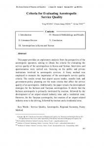
drill and paddle. Attempts to mix DOTLine in larger volumes resulted in flash-set of the material. Pavemend TR was successfully mixed using a 1-yd3 horizontal shaft mixer. However, build-up of material within the mixer was undesirable. Additionally, Pavemend TR was difficult to finish resulting in a rough surface appearance (Figure 2). These repair materials are more appropriate for small patches that are better suited for bucket mixing limited volumes of material. Pavemend TR also requires curing of at least 4 hr prior to traffic compared to only 2 to 3 hr for the other materials.
Figure 2. Pavemend TR surface.
Materials such as Great White and Rapid Set Concrete Mix are appropriate when larger mix volumes are necessary and are best suited for proportional mixers. The use of a proportional mixer requires advanced calibration of the equipment with the material, thus they should only be used when experienced operators have been trained on using the material with the mixer. ABC Cement was suited for various sized repairs and could be mixed in a variety of volumes, but the material required the use of liquid admixtures instead of water. Rapid Set Concrete Mix could be mixed in small and large volumes with various pieces of equipment. The recommendation for repair type is also presented in Table 5.
ERDC/GSL TR-11-13
17
Table 5. 2008-2009 Summary of products, results, and recommendation by agency. No.
Product
Manufacturer
Result
Recommendation
Agency
1
Rapid Set Concrete Mix
CTS Cement
Pass
Spall repair, small patches, large patches, full-slab replacement, small and large crater repair
ERDC
2
Pavemend SLQ
Ceratech, Inc.
Fail
Spall repair, Small patches
ERDC
3
Pavemend SL
Ceratach, Inc.
Fail
Not recommended
ERDC
3
ABC Cement
ABC
Pass
Spall repair, small patches, large patches, full-slab replacement, small crater repair
ERDC
4
DOTLine
Ceratech, Inc.
Fail
Not approved
ERDC*
5
Mainline
Ceratech, Inc.
Fail
Not approved
ERDC*
6
Great White
Ceratech, Inc.
Fail
Slab replacement
ERDC*
7
Pavemend TR
Ceratech, Inc.
Fail
Approved with 4 hr cure. Spall repair, small patches, and large patches
ERDC
As shown in Table 5, although some materials such as Pavemend SLQ, Great White, and Pavemend TR (with 4 hr of cure) did not meet minimum recommendations for compressive strength and slant shear results (“fail” in the table), they were initially approved for use. This approval was based on good field test results shown in Table 6. Due to low pass-to-failure results for Pavemend SL and DOTLine, these materials were not recommended for airfield repairs. DOTLine also failed shrinkage potential laboratory tests. Mainline was not field tested; however, laboratory results do not indicate that this repair material would be suitable for airfield repair. Laboratory test results are presented in Appendices C and D.
Laboratory tests 2009-2010 During 2010, ERDC conducted tests, in accordance with requirements of ETL 08-02 (AFCESA 2008a), on several products including repeat testing on ABC Cement, PavePatch 3000, Set 45HW, Rapid Set Concrete Mix, and Premium Patch 200. Results for materials tested during this period of investigation are provided in Table 7. Not all tests required by the ETL were conducted when initial results indicated failure of the materials; specifically, bond strength, volumetric expansion, and shrinkage potential were not tested. Field validation tests were not conducted on the materials tested during this time. Several of the materials had been field tested
ERDC/GSL TR-11-13
18
Table 6. Summary of traffic tests on cementitious materials 2008-2009.
Repair
Cap Thickness, Capping Material in.
Failure Mode
Failure Detail
Passes To Failure
1
Rapid Set Concrete Mix
6
FOD
High-severity joint/corner spalls
784
2
Pavemend SLQ
6
FOD
High-severity joint spalls
455
3
DOTLine
6
FOD
High-severity joint spalls
224
4
Pavemend TR
6
Curing
Uncured material
40
5
Pavemend SL
6
FOD
High-severity joint spalls
144
6
Mainline
6
Not tested
7
Great White
9
No failure
No failure
2,000
8
ABC Cement
9
FOD
High-severity joint spalls
2,000
9
Pavemend TR
9
No failure
No failure
5,000
Table 7. 2009-2010 Summary of products, results, and recommendation by agency. No.
Product
Manufacturer
Result Recommendation
Agency
1
Speedcrete 2028
Euclid Chemical
Fail
Not recommended
MST
2
Set 45HW
BASF Building Solutions
Fail
Spall repair, small patches and large patches, and small crater repair
MST
3
ABC Cement
ABC
Fail
Small patches, large patches, full-slab replacement, small crater repair
MST
4
HD-50 Rapid Set
Dayton Superior
Fail
Expeditionary spall repairs, small patches, spall repair
MST
5
PavePatch 3000
Conspec Co.
Fail
Expeditionary spall repairs, small patches, spall repair
MST
6
Quikrete Fast Set DOT Mix
Quikcrete
Pass
Expeditionary spall repairs, small patches, spall repair
MST
7
Rapid Set Concrete Mix
CTS Cement
Pass
Spall repairs, small patches, large patches, slab replacement, small and large crater repair
MST
8
Rapid Set Concrete Mix
CTS Cement
Pass
Spall repairs, small patches, large patches, slab replacement, small and large crater repair
ERDCa
9
HD-50
Dayton Superior
Pass
Expeditionary spall repairs, small patches, spall repair
ERDCa
10
Premium Patch Pre-Blend 200 Products, Inc.
Pass
Expeditionary spall repairs, small patches, spall repair
ERDCa
12
Fastrac Concrete Mix
Fail
Not recommended
ERDCa
a
Western Material & Design, LLC
Material tested by Burns, Cooley, Dennis, Inc.
ERDC/GSL TR-11-13
previously, including Set 45HW, ABC Cement, HD-50 Rapid Set, and Rapid Set Concrete Mix. Fact sheets detailing those test results are presented in the Appendices E and F. Based on results of the laboratory tests performed, only two of the materials tested, Quikcrete Fast Set DOT Mix and Rapid Set Concrete Mix, met the minimum standards set forth in the ETL. Although no field testing was conducted on Quikcrete Fast Set DOT Mix, its high early compressive strengths indicate that this material may be suitable for expeditionary spall repairs, spall repairs, and small patches. Because there was no field test data for placement or traffic data, this material was not recommended for large patches or crater repair. Recommendations for use of Rapid Set Concrete Mix, based on the prior testing detailed in previous sections, were not changed as a result of retesting. Two materials, Speedcrete and Fastrac Concrete Mix, tested during this time were not recommended for use. Speedcrete was not recommended because of its low compressive strength at 2 hr and the lack of field placement and trafficking data for the material. Fastrac Concrete Mix was not recommended because it was too difficult to mix and place without the addition of citric acid. However, when citric acid was added, the material failed to develop adequate compressive strength as shown in the fact sheets in Appendix E. The remaining materials tested in 2009 through 2010 did not meet minimum test requirements as detailed in the current version of ETL 08-02 (AFCESA 2008a). The recommendations presented in Table 7 are based on results of laboratory testing and field test results conducted in previous years by ERDC or AFRL as discussed in previous sections.
Shortfalls of previous research Based on review of the previous studies and requirements of ETL 08-02, few repair materials met all current ETL requirements. Despite not meeting minimum laboratory performance criteria, several cementitious repair materials were initially recommended for use based on good field performance. This indicated that a review of the test requirements compared to field results was needed. Additionally, because some materials were only suitable for a specific size (small or large) repair, a general approval of the material as a repair material was not appropriate. Repair materials should be approved for the different volume applications (spall repair, small
19
ERDC/GSL TR-11-13
patching, large patching, or full-slab replacement) or repair types (temporary vs. permanent) to which they are best suited. The following chapters detail the test procedures used for the cementitious materials, compare test results of the different products, propose changes to the current requirements, and provide recommendations for use of repair materials by repair size and type.
20
ERDC/GSL TR-11-13
3
Cementitious Material Laboratory Test Descriptions This section summarizes various material characterization parameters and the various test methods employed to evaluate the cementitious, rapidsetting materials addressed in this study.
Strength For determining suitability of a pavement for opening to traffic, the strength criterion is often the most stringent requirement, especially for rapid-setting concretes. For highway and airfield agencies, strength criterion is usually reported as either flexural strength or compressive strength. Although flexural strength can be correlated to compressive strength, current criteria may vary in the test used or require that both be reported. The cementitious, rapid-setting repair materials must meet or exceed the criterion set for strength prior to returning the pavement to service. Compressive strength Minimum compressive strength criterion is important for ensuring that the concrete will not crush easily under wheel loads or under stresses caused by environmentally induced pavement movements. Compressive strength testing was accomplished in accordance with ASTM C 39 procedures (ASTM 2005). The compressive strength of concrete mixtures was evaluated by testing 4-in. × 8-in. cylinders. Methods of curing and capping the specimens are addressed in a later section. The duration of curing, prior to testing, was either 2 hr or 24 hr. The curing duration was established as the time elapsed from final finishing to testing of a specimen, not the time elapsed from initial set of the material to the time of testing. Results were reported as maximum compressive stress (psi), which equals the maximum applied load divided by the specimen’s initial, unloaded cross-sectional area. Figure 3 shows a compressive specimen after testing. Flexural strength In addition to resisting crushing forces, the cementitious material must also resist bending forces or flexure. Flexural strength testing was
21
ERDC/GSL TR-11-13
22
Figure 3. Compressive specimen after test.
conducted in accordance to ASTM C 78 procedures (ASTM 1994; ASTM 2008b). The test specimens were rectangular beams with typical dimensions of 6-in. × 6-in. × 18-in. long. Tests were conducted on the specimens with an unsupported span equal (within 2 percent variation) to three times its depth. Loading was applied at third-points of the span. Figure 4 shows beam specimens during curing. The beams were cured the same as previously described for the cylinders. Figure 5 shows a cured beam undergoing testing. Results were reported as the ultimate tensile stress achieved before failure, also known as the modulus of rupture (psi).
Bond strength Bond strength is important for ensuring that the material used for spall repair will adhere to the damaged pavement material and not become easily dislodged under trafficking. Bond strength testing was conducted in accordance with the requirements of ASTM C882 (2005a). This procedure involves the preparation of specimens in 3-in. × 6-in. cylinder molds. A bond line was produced at approximately 30 deg from vertical by first casting wedge-shaped dummy sections of either ordinary portland cement (OPC) mortar or the repair material itself in the cylinder molds. After
ERDC/GSL TR-11-13
23
Figure 4. Flexural beams.
Figure 5. Flexural beams undergoing test.
ERDC/GSL TR-11-13
24
curing these wedge-shaped sections, the repair material was placed on top of the dummy section in the mold and cured for 1 day. Curing and capping methods for the cylinders are addressed in a later section. The composite cylinder, produced with repair material bonded either to OPC mortar or to itself, was tested in compression (Figure 6). Results were reported as maximum bond stress (psi), which was calculated as maximum axial load divided by the area of the elliptical bonding surface.
Figure 6. Slant shear sample undergoing test.
Time of setting Working time, for materials considered in this study, was defined as the elapsed time between the initial contact of water with the repair material and the initial set of the material. Because of the short working times associated with rapid-setting cementitious materials, it becomes an important consideration in selecting a material to accomplish a repair. Testing was accomplished in accordance with ASTM 403/C 403M (ASTM 2006). For this testing, a properly proportioned paste of the subject material is mixed to normal consistency and molded. Periodic penetration tests are performed on this paste by forcing a standardized needle downward into the paste and recording the time required for the needle to penetrate 1 in. into this paste. The penetration resistance was calculated by dividing the
ERDC/GSL TR-11-13
recorded force by the bearing area of the needle. The initial time of setting was the time elapsed between the initial contact of cement and water and the time when the penetration resistance equaled 500 psi. The final time of setting was the time elapsed between initial contact of the cement and water and the time when the penetration resistance equaled 4,000 psi. Time of setting was reported in minutes. Testing began immediately after the paste is mixed due to fast set times associated with these repair materials.
Shrinkage Shrinkage potential includes drying shrinkage, thermal shrinkage, and autogenous shrinkage, all of which occur during hydration. Shrinkage potential is important because repair materials that shrink excessively are more prone to bonding problems and to shrinkage-related cracking. Shrinkage was measured using a restraining ring device, in accordance with ASTM C 1581 (ASTM 2004a). While this procedure was slightly more involved than the traditional linear bar shrinkage test, which can be accomplished in conjunction with the coefficient of thermal expansion test ASTM C 531 (ASTM 2000, 2005b), the use of restraint was an attempt to capture all components of shrinkage previously listed. The linear bar shrinkage test is limited to measuring only drying shrinkage. The restraining ring was constructed with structural steel pipe with a wall thickness of 0.5 in., an outside diameter of 13 in., and a height of 6 in. The concrete mix was cast on the outside of the restraining ring in a manner that produced a material ring with a height of 6 in. and a wall thickness of 1-1/2 in. The repair ring was moist cured at 73.5°F for 24 hr. Then, the outer form that was used to shape the repair ring was removed and the top of the repair ring was sealed so that all drying occurs on the outer circumference of the repair ring. The restraining ring stayed in place during the entire test. The repair ring then cured in an environment with 50 percent relative humidity and a temperature of 73.5°F for 28 days during which the ring was monitored for cracking and the circumferential strain on the inside of the restraining ring was measured using foil strain gages. Results reported included ring strain at the end of moist curing, age at the time of first crack (if cracking occurs), and ring strain at either the age at the time of first crack or 28 days if cracking never occurs. The ages were computed from the time of casting the repair ring. Figure 7 presents a sample undergoing strain measurement. Figure 8 presents a sample that has cracked prior to 28 days.
25
ERDC/GSL TR-11-13
26
Figure 7. Ring shrinkage sample prior to cracking.
Figure 8. Ring shrinkage sample after cracking.
ERDC/GSL TR-11-13
27
Modulus of elasticity Modulus of elasticity is important because a cementitious repair material should not have stiffness significantly different than the parent material onto which it is applied. With a higher stiffness, the repair material would assume higher stresses under wheel loading and pavement movement. In terms of bonding, significant differences in stiffness would change the amount of strain/deflection between the parent slab and repair material. This would be particularly true in the tension zone where differential deflections would lead to patches exceeding the parent materials bond strengths resulting in debonding. Modulus of elasticity testing (Figure 9) was accomplished in accordance with ASTM C 469 procedures (ASTM 2010a). Cylinders were either 3 in. × 6 in. or 6 in. × 12 in. In this method, a bonded or unbonded sensing device was attached to the cylinder at mid-height for the purpose of measuring vertical deformation. The gage length of the measurement was at least three times the maximum aggregate size and not more than one-half the specimen height. The modulus of elasticity (with units of psi) was calculated as change in stress divided by change in strain, where strain was calculated as
Figure 9. Sample undergoing modulus of elasticity testing.
ERDC/GSL TR-11-13
vertical deformation divided by the gage length. The calculation, as specified in ASTM C 469 (ASTM 2002), produced a chord modulus of elasticity where the cord line is drawn between the stress at 50 milistrain and the strain at 40 percent of the compressive strength. Tests were conducted after the specimens had cured 2 hr and on other specimens after 3 days. Curing and capping methods for cylinders are addressed in later sections.
Volumetric expansion or contraction Excessive expansion and contraction of material used in a spall repair, due to either internal or external forces, will result in a loss of bond to the parent material. Additionally, if the spall repair is large, excessive expansion of the repair material can result in the deterioration of the surrounding pavements. Coefficient of thermal expansion The material’s coefficient of thermal expansion is important because a repair material with a coefficient of thermal expansion that is significantly greater than the parent material would experience greater volume changes with changes in temperature (volumetric expansion due to externally applied forces). The difference in movements for the repair material versus the parent material would tend to deteriorate the bond between the two materials. Coefficient of thermal expansion testing was accomplished in accordance with ASTM C 531 procedures (ASTM 2000, 2005b). These procedures involved the production of prismatic bars (1 in. × 1 in. × 10 in.) with metal studs on each end. The studs facilitated length measurements. The lengths of the bars were measured at both 73°F and 210°F. The coefficient of thermal expansion was calculated as strain per degree F, with units of in./in./°F. Testing began after the prisms cured 3 days. Length change Because volumetric expansion of repair materials can result from causes other than applied force or temperature changes, testing for expansion due to internal forces was accomplished according to ASTM C 157 procedures (ASTM 2008c). If a spall repair material experienced length changes greater than +0.03% (expansion) or less than -0.04 percent (contraction), this may have resulted in deterioration of the bond with the parent material and deterioration of the parent material itself. Following ASTM C 157 procedures, test specimens were prismatic bars with dimensions based on
28
ERDC/GSL TR-11-13
maximum aggregate size. For repair materials with maximum aggregate size of 0.75 in., prismatic bars were 3 in. × 3 in. × 11.25 in. with metal studs on each end. The studs facilitated length measurements. The bars were then cured in either water at 73°F or air at 73°F with a 50 percent relative humidity. Readings were taken during curing after 4, 7, 14, and 28 days and after 8, 16, 32, and 64 weeks. Specimens were removed from the molds 2.5 to 2.75 hr after the addition of mixing water. Initial observations of length were made 3 to 3.25 hr after the addition of mixing water according to ASTM C 928 (ASTM 2009) standard. The length change at each age was calculated as a percentage (change in length/original length × 100 percent).
Methods of curing and capping Although the curing and capping of laboratory specimens are not tests, they are important considerations for purposes of accomplishing accurate and consistent testing. Curing Curing affects all tests previously described, but note that the restraining ring shrinkage test involves specific curing conditions that must be met. For the other tests, curing optimally reflected the type of curing that will be accomplished in field placements. It also reflected the type of curing that was recommended by the repair material’s manufacturer. When in doubt about the anticipated field procedures, materials were air cured at room temperature and 50 percent relative humidity to impose less than optimal, but realistic, curing conditions. Curing conditions were reported with the test results. To reflect field performance, curing durations for this report, unless specifically noted, were the time elapsed from the final finishing of a test specimen to the time of testing, not the time elapsed from the initial set of the material to the time of testing. Capping Capping affects compressive strength, bond strength, and modulus of elasticity testing. Capping was necessary to provide flat ends that were perpendicular to the sides of the cylinders to ensure proper loading during testing. Capping was accomplished with either bonded materials (ASTM C 617)(ASTM 2010b) or unbonded pad caps (ASTM C 1231) (ASTM 2008a). For this protocol, compressive strength and bond strength testing were accomplished with unbonded pad caps. Modulus of elasticity testing
29
ERDC/GSL TR-11-13
required the use of bonded caps. Capping methods were also reported with the test results.
Replicates Three replicates were required for each of the tests described in this report. The average result, calculated from the three replicates, was compared to the requirements presented in the ETLs. The average of only two replicates was not acceptable.
30
ERDC/GSL TR-11-13
4
31
Results and Discussion Since the development of ETL 08-02 (AFCESA 2008a), the American Society for Testing and Materials approved a standard for rapid-setting cementitious materials. ASTM C 928 (ASTM 2009) defines three types of packaged, dry, rapid-hardening concretes/mortars as R1, R2, and R3. This standard also provides performance requirements for length change, consistency, and scaling resistance. Table 8 presents the performance requirements required by the standard. Table 8. ASTM C928 requirements for cementitious, rapid-setting materials.
ERDC/GSL TR-11-13
Optional characteristics that are recommended for consideration are time of setting, flexural strength, freeze thaw, and sulfate expansion. No tests of consistency, freeze thaw, or sulfate expansion conducted on any of the products tested at the ERDC or AFRL are available for comparison with the new ASTM standard. The following sections provide analyses of test results conducted at ERDC and other agencies to determine if current requirements set forth in ETL 08-02 (AFCESA 2008a) or ASTM C 928 (ASTM 2009) are appropriate for down selecting repair materials. Compressive strength As can be seen in Table 8, for ASTM C 928 (ASTM 2009), repair materials are separated based solely on their compressive strength at 3 hr, 1 day, and 7 days of cure. R1 materials are only required to gain 500 psi; R2 materials are to gain 1,000 psi; and finally, R3 materials are to gain 3,000 psi compressive strength within 3 hr as measured using ASTM C 39 (ASTM 2005) procedures. As can be seen in Figure 10, the majority of tests conducted on products gained over 2,500 psi within 2 hr of cure placing most of the rapid-setting cementitious products tested in this program in the R3 category as defined by ASTM C 928 (ASTM 2009). The current ETL requires 3,000 psi at 2 hr. Not all products tested gained this strength at 2 hr. The 2-hr requirement is critical for crater repairs during initial base recovery activities and repairs on primary runways or taxiways where expedited return to service is required. However, for permanent airfield repair activities in less critical areas, longer cure times may be possible. Obtaining 3,000 psi within the cure time available for the repair may be more applicable for permanent airfield repair activities conducted on parking aprons and secondary taxiways. For example, many materials did not achieve 3,000 psi at 2 hr, but may have achieved 3,000 psi in 3 hr of cure that would classify them as R3 materials according to the new ASTM standard. This would increase the number of repair materials adequate for repairs with a 3-hr cure time. Comparisons of compressive strengths at one day of cure are shown in Figure 11. No 24-hr test data were available for the tests conducted at MST. Not all products that met the R3 compressive strength criteria at 3 hr gained 5,000 psi strength within one day. Data were not available for 7-day and 28-day test result comparison with the ASTM standard.
32
ERDC/GSL TR-11-13
Figure 10. Product comparison of 2-hr compressive strength.
33
ERDC/GSL TR-11-13
Figure 11. Product comparison of 24-hr compressive strength.
34
ERDC/GSL TR-11-13
The requirement for 5,000 psi at 1 day may be most important for crater and expeditionary spall repairs that will be experiencing heavy traffic volumes within hours of repair. This requirement may also be relevant to permanent airfield repairs conducted on runway and primary taxiway surfaces. Obtaining 5,000 psi at 7 days and 28 days is suitable for permanent airfield repairs on parking aprons and secondary taxiways. It is recommended that a minimum requirement be added to the ETL for crater and expeditionary spall repairs to obtain a minimum of 5,000 psi at 1-day cure. For permanent repairs on airfields 5,000 psi should be achieved by 7 days and maintained at 28 days. It is also recommended that the 2-hr, 3,000-psi requirement remain the minimum requirement for crater and expeditionary spall repair activities as these repairs will experience heavy traffic volumes within hours of repair. For repairs conducted on parking aprons and secondary taxiways, 3,000 psi at a specific curing time (based on repair windows for that airfield) should be specified. Several products underwent repeat testing including Pavepatch 3000, Pavemend TR, ABC Cement, Pavemend SLQ, Set 45HW, HD-50 Rapid Set, Thoroc 10-61, and Rapid Set DOT Mix. As can be seen in these figures, variations occurred between test agencies and test years for similar products. These differences are not uncommon, as the rapid-setting cementitious materials may vary due to differences in cement chemistry and product formulation from year to year. Additionally, ranges of water content are allowed for several products, and most products that allow extension with aggregate permit “up to” a certain weight of aggregate usually pea gravel or maximum size of 0.75-in. crushed stone. Unless identical water and aggregate types/volumes are added to prepare the materials, the compressive strength of the materials will vary. For example, Rapid Set Concrete Mix’s manufacturer mixing recommendations permit the addition of 3 to 5 qt of water per 60-lb sack of material. Figure 12 shows the difference in early compressive strength when 3.5 and 5 qt of water per 60-lb sack of material are used. If the maximum water content allowed (5 qt) is added, then the material did not gain the 3,000-psi requirement until almost 14 hr of cure. When 3.5 to 4.5 qt are added, the material achieves 3,000 psi within 2 to 3 hr. These data indicate that unless identical volumes of water were used to prepare the laboratory samples from each laboratory, the resulting compressive strengths would vary.
35
ERDC/GSL TR-11-13
Figure 12. Comparison of compressive strengths for Rapid Set Concrete Mix for varied water contents.
Due to limited record keeping, the liquid and aggregate amounts added for laboratory batching were not always recorded on the data sheets provided in the appendices. It is recommended that this information should be required to be placed in each fact sheet under “mixing instructions” for future tests conducted for this program. If water and aggregate volumes were controlled between materials tested, material reformulation would be better indicated by drastic differences between testing over time. Because reformulation of materials or changes in component chemistry are common for these product types (Priddy et al. 2007), retest of materials following identical laboratory procedures are recommended. As mentioned in “Background”( Chapter 2), NTEP retests materials every 5 years to check for reformulation changes to material properties. Unless the material vendor discloses a reformulation of material and new mixing instructions, identical mixing procedures to previous tests should be followed. It is recommended that materials be retested every 5 years.
36
ERDC/GSL TR-11-13
Flexural strength Flexural strength tests were conducted on numerous products as presented previously. ASTM C 928 (ASTM 2009) does not provide minimum performance requirements for this test (ASTM C 78) (ASTM 1994; ASTM 2008b). The current ETL 08-02 (AFCESA 2008a) requires that the materials develop a minimum flexural strength of 350 psi within 2 hr and recommends testing again at 1 day, but the ETL does not require a minimum value for the 1-day test. Flexural strength is commonly required for acceptance of materials used in PCC airfield construction; however, many agencies now specify compressive strength in lieu of flexural strength. PCC is usually assumed to be about 10 to 12 percent as strong in tension as it is in compression. Tensile strength is the basis for its ability to resist bending, or its flexural strength. Resistance to bending without cracking may be more important for full-slab replacements than for smaller repairs such as spalls, small patches, and large patches that may not experience large tensile forces. Figure 13 presents the 2-hr flexural strength results for the products tested. The current requirement of 350 psi is almost met or exceeded by the majority of products tested. A 350-psi minimum strength at 2 hr is most likely adequate for repair material selection for full-slab replacement for permanent airfield repairs and for large crater repairs involving multislab replacement. By 7 days and 28 days, the repair material should obtain 600 psi assuming the minimum compressive strength at 28 days is 5,000 psi, 12 percent of this is 600 psi. Materials not meeting minimum requirements are not recommended for full-slab replacement. It is recommended that the ETL be modified so that the minimum requirement at 2 hr is 350 psi with a 600-psi minimum at 7 days and 28 days to be consistent with the recommendation for the compressive strength minimum requirements for full-slab replacement activities only on primary runways and taxiways. Longer cure times (i.e., 350 psi at 3 hr) may be specified for parking aprons and secondary taxiways; however, the 600-psi requirement at 7 and 28 days should remain. Bond strength Bond strength tests were conducted on numerous products. ASTM C 928 (ASTM 2009) provides minimum performance requirements for this test of 1,000 psi at 1 day and 1,500 psi at 7 days for cementitious, rapid-setting
37
ERDC/GSL TR-11-13
Figure 13. Product comparison of 2-hr flexural strength. 38
ERDC/GSL TR-11-13
repair material bonded to OPC. The current ETL 08-02 (AFCESA 2008a) requires testing for both rapid-setting material bonded to OPC and rapidsetting material bonded to rapid-setting material. A minimum of 850 psi is required at 1 day for cementitious, rapid-setting repair material bonded to OPC and 1,000 psi for cementitious, rapid-setting repair material bonded to cementitious, rapid-setting repair material. Figure 14 presents a comparison of the bond strength of repair materials bonded to OPC after 1 day of cure. Figure 15 presents the bond strength of repair materials bonded to themselves after 1 day of cure. Bond testing was always conducted, but most materials investigated are represented in this figure. The current requirement of 850 psi is almost met or exceeded by the majority of products tested. The only bond problem evidenced in field testing of the numerous products was with Express Repair in 2007 which exhibited a bond strength of 720 psi. This was below the minimum requirement of 850 psi. The ETL requirement of 850 psi could be modified to match the ASTM C 928’s 1,000-psi requirement (ASTM 2009). Fewer tests have been accomplished with the rapid-setting material to rapidsetting material. The available data are presented in Figure 14. The only material not meeting a minimum requirement of 1,000 psi was Express Repair. Bond strength is important for expeditionary spall repairs; however, materials that performed well for temporary spall repairs including Futura 15, Pavemend TR, and Pavemend VR were below the minimum value for bond strength of repair material bonded to OPC. Changing the bond strength between a repair material and itself in the ETL to 1,000 psi is recommended. Further, long-term investigation is also recommended to determine if repairs made with materials recommended for expeditionary spall repairs perform adequately long term despite reduced bond strength results. Modulus of elasticity Figure 16 presents the modulus of elasticity as measured for products following a 2-hr cure. Figure 17 shows the range in values for the materials tested after a 3-day cure. As can be seen by the figure, some materials exceeded the current ETL requirements of being greater than 2 × 10⁶ psi after 2 hr and greater than 4 × 10⁶ psi after 3 days of cure. Mindess et al. (2003) provided a range of acceptable modulus of elasticity values for
39
ERDC/GSL TR-11-13
Figure 14. Comparison of product bond strength to OPC at 1-day cure. 40
ERDC/GSL TR-11-13
Figure 15. Comparison of product bond strength to self at 1-day cure. 41
ERDC/GSL TR-11-13
Figure 16. Comparison of product modulus of elasticity after 2-hr cure. 42
ERDC/GSL TR-11-13
Figure 17. Comparison of product modulus of elasticity after 3-day cure. 43
ERDC/GSL TR-11-13
normal PCC between 2 × 10⁶ and 6 × 10⁶ psi measured at 28 days. The requirement of 4 × 10⁶ psi at 3 days had been set as the average between the normal PCC range, and the requirement of being less than 2 × 10⁶ psi after 2 hr was set based on the lower bound of normal PCC ranges. By setting an upper limit for the repair materials to 6 × 10⁶ psi, testing at 2 hr and 28 days may be a more reasonable requirement for the repair materials. Because the materials gain strength so quickly, it is important for the materials to have reached at least 2 × 10⁶ psi within 2 hr but not to exceed 6 × 10⁶ psi in either the 2-hr or the 28-day test. It is recommended that the ETL be modified to reflect that range in the modulus for both tests. Coefficient of linear thermal expansion In 2008, Priddy et al. reported significant volume changes on repairs performed using Pavemend SLQ. Because shrinkage and expansion problems occurred, it was recommended that repair materials have a coefficient of thermal expansion similar to normal PCC pavements. Excessive expansion will result in the loss of bond to the parent material. Additionally, for large repairs, excessive expansion can result in the deterioration of the surrounding pavements. The coefficient of linear thermal expansion upper limit is typically 8 to 12 × 10-6 in./in./ºF for normal concrete. ASTM C 928 (ASTM 2009) does not set minimum or maximum values for this property as measured by ASTM C 531. In ETL 08-02 (AFCESA 2008a), the current requirement is for the repair material to have a value of ≤7× 10⁻⁶ in./in./°F beginning at a test age of 3 days. As shown in Figure 18, not all materials tested have been tested for their expansive properties. As can be seen by this figure, all but one of the materials tested were within the current requirement set by the ETL. A more recent test of the material shows that this property (as with other properties) varies with year and agency. This is most likely due to water contents and aggregates within the mixes that vary from one test year to the next. However, if one considers the normal concrete acceptable maximum range of 8 to 12 × 10-6 in./in./°F, all the repair materials test results presented in the figure are within the acceptable range. This indicates that the testing did not identify any material that exhibited thermal expansion characteristics that exceed those of normal concrete (which should not result in damage to surrounding pavements if the materials are used for long-term repair and replacement).
44
ERDC/GSL TR-11-13
Figure 18. Comparison of product coefficient of linear thermal expansion after 7-day cure. 45
ERDC/GSL TR-11-13
It is recommended that the requirement in the ETL be changed to an upper limit of 12 × 10-6 in./in./°F with a test age of 7 days, not 3 days as currently shown, to agree with ASTM requirements for this test procedure. Volumetric expansion/shrinkage Because shrinkage and expansion problems have occurred with repair materials in the past (Priddy et al. 2008), it was recommended that repair materials be subjected to additional expansion and shrinkage tests including maximum length change requirements. Excessive expansion or shrinkage will result in the loss of bond to the parent material. Additionally, for large repairs, excessive expansion can result in the deterioration of the surrounding pavements. ETL 08-02 (AFCESA 2008a) requires that the maximum allowable increase in length not exceed 0.03 percent when cured in water and the maximum allowable decrease not exceed 0.04 percent after 28 days curing in air when tested in accordance with ASTM C 157 (ASTM 2008c). These values were set forth in the ETL based on typically accepted values for normal PCC of 0.03 to 0.05 percent (Priddy et al. 2008). ASTM C 928 (ASTM 2009) provides the maximum allowable increase in length change as 0.15 percent after 28 days in water and the maximum allowable decrease as -0.15 percent after 28 days in air. This range for maximum allowable expansion and contraction is so broad that most materials fall between the limits. These values were determined based on the investigation of a single repair material by seven different laboratories as detailed in ASTM C 928. As mentioned previously, in 2008, Priddy et al. identified a problem of significant volume changes with Pavemend SLQ. Laboratory testing of this material, from the same batch of material used in the field tests where the problem occurred, measured a maximum length change (expansion) of a specimen cured in a moist cabinet held at 73°F on the order of 0.15 percent. No shrinkage was recorded. Based on both the ETL data, this material would not have been acceptable due to its expansive properties. According to ASTM C 928, the material would have been borderline acceptable. Results of investigations into additional repair materials in 2009 and 2010 are presented in Figure 19. Data presented in the figure only include materials tested after expansion problems were identified in the repair materials. Most of the remaining repair materials met the requirements of the
46
ERDC/GSL TR-11-13
Figure 19. Comparison of repair material expansion and shrinkage percentages (length change). 47
ERDC/GSL TR-11-13
current ETL for shrinkage and expansion. Exceptions were DOTLine and Mainline that failed due to excessive shrinkage and Fastrac Concrete Mix that failed due to excessive expansion. Long-term investigation into expansion and shrinkage is recommended to determine if the current ETL requirements should be changed to match the ASTM requirements. However, the initial data indicate that the new ASTM standard is too permissive. DOTLine did not perform well in field tests, and Fastrac has not been field tested. Additionally, only few repairs have been left in place for assessment of long-term repair performance (including Pavemend SLQ, Rapid Set Concrete Mix, Set 45 HW, Thoroc 10-60, and Thoroc 10-61). Until further investigations are completed, it is recommended that the ETL requirements remain the same for all repair types. Shrinkage potential ASTM C 928 (ASTM 2009) does not provide a requirement for conducting tests of shrinkage potential outside of ASTM C 157 (ASTM 2008c) testing. The restrained ring device is specified as an additional test of shrinkage in ETL 08-02 (AFCESA 2008a). The ETL requires that less than 40 microstrain be measured after 14 days and that no cracking occur within 28 days of casting. Data were collected following ASTM C 1581 (ASTM 2004a) during FY08 through FY10 (Table 9). No data were available for products tested prior to FY08. Additionally, no ring shrinkage test results were available for products tested by MST. The ring shrinkage data agreed with the length change data presented previously that Mainline and DOTLine experienced more shrinkage than the other products tested. The remaining products tested met the requirements set forth in the ETL. No changes to the ETL are recommended for this test, and the requirement is recommended for application to all repair types. Freeze thaw Currently, no freeze-thaw requirements are set forth in ETL 08-02 (AFCESA 2008a). When the ETL was first drafted, consideration was given to a requirement that the repair materials should have ≤50 percent loss in relative dynamic modulus of elasticity after 50 freeze-thaw cycles with testing to be done after 3 days of cure following ASTM C 666 (ASTM 2008d). ASTM C 928 also recommends using ASTM C 666 (ASTM 2008d) test procedure but requires only 25 cycles of freezing and thawing.
48
ERDC/GSL TR-11-13
49
Table 9. Ring shrinkage test results FY08-FY10. Product
Test Year
Test Agency
Pass/Fail
Pavemend TR-ERDC FY08
FY08
ERDC
Pass
Pavemend SLQ-ERDC FY08
FY08
ERDC
Pass
Rapid Set Concrete Mix-ERDC FY08
FY08
ERDC
Pass
ABC Cement -ERDC FY08
FY08
ERDC
Pass
Mainline-ERDC FY09
FY09
ERDC
Fail
DOTLine-ERDC FY09
FY09
ERDC
Fail
Great White-ERDC FY09
FY09
ERDC
Pass
Rapid Set Concrete Mix-ERDC FY10
FY10
ERDC
Pass
HD-50-ERDC FY10
FY10
ERDC
Pass
Premium Patch 200-ERDC FY10
FY10
ERDC
Pass
Fastrac Concrete Mix-ERDC FY10
FY10
ERDC
Pass
ASTM C 928 (ASTM 2009) also recommends recording the scaling resistance to deicing chemicals after 25 cycles in accordance to ASTM C 672/C 672M (ASTM 2003) with the exception of omitting data collection at 5 cycles. For this test, the maximum visual rating is 2.5 for concrete and maximum scaled material is 1 lb/ft2 for mortar. It is recommended that freeze-thaw and scaling resistance be investigated for the top performing repair materials, as identified through the 5 years of investigation. The testing requirements described in ASTM C 928 tests should be conducted as a minimum to identify requirements for ETL 08-02 (AFCESA 2008a). Once requirements are determined, application of the requirement should be restricted to airfields that undergo freeze-thaw cycling. Set time The amount of working time available for cementitious, rapid-setting repair material placement is important to those performing repairs. For large repairs, the set time needs to be long enough so that the entire repair may be placed before portions begin to set in order to reduce the need for a number of thin horizontal lifts or the need for setting formwork for placing smaller full-depth sections. As mentioned previously, many materials require mixing in buckets or in small volumes. These materials generally have shorter initial and final set times, some as short as 5 min or less. Set times this short would require mixing numerous small batches of material
ERDC/GSL TR-11-13
or simultaneous mixing of multiple batches for a large repair. Even so, thin horizontal lifts may occur. Time of set for initial and final setting of materials, as measured in accordance with ASTM C 191 (ASTM 2004b), has been collected for materials over the last several years and is presented in Figure 20. Set time data collected in 2007 by ERDC was not included in this figure because the values were not measured according to ASTM C 191 (ASTM 2004b). The data presented in this figure show the majority of repair products achieve initial set within 35 min and final set within 45 min. Because larger volumes of repair materials are required for crater repairs, large patches, and full-slab replacements, an initial set greater than 15 min and a final set of greater than 25 to 35 min are recommended. Shorter initial set times for spall repairs and small patches may be allowed as less working time is required for these smaller volume repairs. Obviously extended set times would negate the “rapid-setting” nature of these materials. Thus, a maximum set time of 45 min should be maintained to ensure that the chemical reactions are progressing and provide the material with enough active cure time to achieve the required strength values. Slump ASTM C 928 (ASTM 2009) recommends a minimum slump of 3 in. for cementitious, rapid-setting materials. No slump requirements are currently set forth in ETL 08-02 (AFCESA 2008a); however a recommendation of 3 in. is a reasonable requirement for ease-of-placement of materials. A higher slump may be required for large crater repair and full-slab replacement to reduce labor on workers conducting the repairs. Specifying a higher slump increases the risk that segregation of aggregate may occur. No slump data exist for materials tested at ERDC, but it is recommended that future work include this test.
50
ERDC/GSL TR-11-13
Figure 20. Comparison of set times for materials. 51
ERDC/GSL TR-11-13
5
Conclusions and Recommendations This research identified the key characteristics of successful rapid-setting repair materials, tested a number of repair materials currently used or marketed to the DOD, and compiled the information for use in a repair material selection process. Additionally, tests were performed on a number of field repairs, and the field placement and performance under simulated aircraft traffic was observed in an effort to correlate laboratory data to field performance results. Even though several tests were conducted in the laboratory to characterize selected material properties, no single property was deemed a sole indicator of performance.
Repair material recommendations A review of laboratory and field tests conducted at ERDC and other agencies from 2006 to present was completed in this investigation. Table 10 provides a repair material selection table to aid repair units or airfield repair managers in selecting materials for particular applications or missions. Fact sheets detailing each product are provided in the appendices.
Performance test parameters Conclusions and recommendations for numerous laboratory test parameters are presented in this section. Table 11 provides a summary for the test requirements recommendations presented in the following sections. Compressive strength Modifications to the ETL for compressive strength are recommended. The following conclusions and recommendations are provided: •
The 2-hr 3,000-psi requirement is important to temporary repairs including crater and expeditionary spall repair activities as these repairs will experience heavy traffic volumes within hours of repair; however, for permanent airfield repair activities, longer cure times may be acceptable.
52
ERDC/GSL TR-11-13
53
Table 10. Repair material/repair type selection table. Temporary Repairs
Permanent Airfield Repairs
Crater Repairs Repair Material
Small
Large
ABC Cement
X
X
Expeditionary Spall Repairs Spall X
Small Large Full Patch Patch Slab
Spall
Small Large Full Patch Patch Slab
X
X
X
X
Great White
X
X
X
HD-50 Rapid Set
X
Pavemend 15
X
Pavemend SLQ
X
Pavepatch 3000
X
Premium Patch 200
X
X
X
X
X
X
X
X
X
X
X
X
X
X
Quikcrete Fast Set DOT Mix
X
X
X
X
X
X
X
X
X
X
X
X
X
X
X
X X
X
Pavemend TRa
Rapid Set Concrete Mix
Secondary Runways, Secondary Taxiways, and Parking Aprons
Primary Runways and Taxiways
X
X
X
Rapid Set DOT Mix Set 45 HW
X
X
X
X
X
X
X
X
Set 45
X
X
X
X
X
X
X
X
X
X
X
X
X
SikaQuick 2500 Thoroc 10-60
X
X
X
X
X
X
X
X
X
X
X
Thoroc 10-61
X
X
X
X
X
X
X
X
X
X
X
Ultimax Concrete Mix
X
X
X
X
X
X
X
X
X
X
X
Versaspeed a
X
Research indicates that this material requires 4 hr of curing prior to opening to traffic.
Temporary Repairs
Permanent Airfield Repairs Secondary Runways, Secondary Taxiways, and Parking Aprons
Property
ASTM
Crater Repair
Expeditionary Spall Repair
Primary Runways and Taxiways
Compressive strength
C 39
≥ 3,000 psi at age of 2 hra ≥ 5,000 psi at age of 1 day
No laboratory requirement at this time. Requires field testing prior to approval.
≥ 3,000 psi at 2 hr or at age of opening ≥ 5,000 psi at age of 1 day
≥ 3,000 psi at specified age of opening ≥ 5,000 psi at age of 7 days and 28 days
Flexural strength
C 78
Not required
Not required
≥ 350 psi at age of 2 hr ≥ 600 psi at age of 7 days and 28 days Full-slab replacement only
≥ 350 psi at specified age of opening ≥ 600 psi at age of 7 days and 28 days Full-slab replacement only
Bond strength
C 882
≥ 1,000 psi (repair bonding to OPC mortar) ≥ 1,000 psi (repair material bonding to repair material) Test at age of 1 day.
≥1,000 psi (repair bonding to OPC mortar) ≥1,000 psi (repair material bonding to repair material) Test at age of 1 day.
≥ 1,000 psi (repair bonding to OPC mortar) ≥ 1,000 psi (repair material bonding to repair material) Test at age of 1 day.
≥1,000 psi (repair bonding to OPC mortar) ≥1,000 psi (repair material bonding to repair material) Test at age of 1 day.
Modulus of elasticity
C 469
2 × 10⁶ to 6 × 10⁶ psi Test at age 2 hr and 28 days.
2 × 10⁶ to 6 × 10⁶ psi Test at age 2 hr and 28 days.
2 × 10⁶ to 6 × 10⁶ psi Test at age 2 hr and 28 days.
2 × 10⁶ to 6 × 10⁶ psi Test at age 2 hr and 28 days.
Volumetric expansion
C 531
≤ 12 × 10-6 in./in./ºF Test begins at age of 7 days.
≤12 x 10-6 in./in./ºF Test begins at age of 7 days.
≤ 12 × 10-6 in./in./ºF Test begins at age of 7 days.
≤ 12 × 10-6 in./in./ºF Test begins at age of 7 days.
C 157