Electrochemical and Solid-State Letters, 7 共4兲 A71-A74 共2004兲
A71
0013-4651/2004/7共4兲/A71/4/$7.00 © The Electrochemical Society, Inc.
Development of Novel Method for Preparation of PEMFC Electrodes Hansung Kim* and Branko N. Popov**,z Center for Electrochemical Engineering, Department of Chemical Engineering, University of South Carolina, Columbia, South Carolina 29208, USA A method based on pulse electrodeposition technique was developed for preparation of membrane electrode assemblies 共MEAs兲. In this approach, platinum is deposited directly on the surface of the carbon electrode. The method ensures most of the platinum to be in close contact with the membrane. Using this method it is possible to increase the Pt/C ratio up to 75 wt % near the surface of the electrode resulting in a 5 m thick catalyst layer. The MEA prepared by pulse electrodeposition exhibits a current density of 0.33 A/cm2 at 0.8 V with platinum loading of 0.25 mg of Pt/cm2 . The results indicate that pulse deposition may be an attractive technique to replace the conventional powder-type MEA preparation methods and help achieve industry goals of reducing catalyst cost and increasing efficiency in polymer electrode membrane fuel cells 共PEMFCs兲. © 2004 The Electrochemical Society. 关DOI: 10.1149/1.1648611兴 All rights reserved. Manuscript submitted August 14, 2003; revised manuscript received September 17, 2003. Available electronically February 10, 2004.
One major impediment to the commercialization of polymer electrolyte membrane fuel cell 共PEMFC兲 technology is the low activity and high content of supported Pt electrocatalyst used for oxygen reduction.1-3 To increase the utilization of the noble catalyst, different methods for manufacturing a membrane electrode assembly 共MEA兲 for PEMFC have been developed over the last decade. Traditionally, platinum salts are reduced chemically using a reducing agent. Platinum particles reduced in solution are in colloidal form. Subsequently, these particles are adsorbed by a high-surfacearea carbon to make a Pt/C powder.4 The ratio of Pt in carbon can be controlled by the initial concentration of Pt salts. However, it is difficult to keep the particle size under 5 nm when the Pt ratio in the Pt/C powder is over 40 wt %. Oxygen reduction activity is directly dependent on the surface area available for reaction and hence on the particle size. Increase in particle size results in decrease of activity and utilization of platinum. Further, this limitation of Pt ratio in carbon also imposes a limitation on decreasing the catalyst layer thickness. Because the ion exchange membrane used in PEMFCs is a solid type, contact between membrane and Pt becomes a critical factor in obtaining a high performance.5,6 For this reason, current approaches aimed at lowering the Pt loading focus on localizing Pt where the electrocatalytic reaction takes place. This has been achieved through a sputtering method on the electrode.7 However, this technique is not a volume production method. It requires expensive vacuum equipment and cannot be used for fabrication of large structures with complex shapes. As a direct deposition technique, electrodeposition has attracted attention due to its ease of preparation and low cost requirement. Taylor et al.8 developed an electrochemical catalyzation 共ECC兲 technique to improve the utilization of Pt catalyst. In this technique, a Nafion solution was impregnated into the uncatalyzed carbon electrode and platinum was electrodeposited from a commercial plating bath. Platinum ions diffuse through a Nafion thin layer formed on the surface of uncatalyzed carbon electrode and are electrodeposited only in regions with ionic and electronic conductivity. Recently, Antoine and Durand9 impregnated carbon with H2 PtCl6 where electrochemical pulses were applied to deposit Pt in a Nafion active layer. This method guarantees a smaller active layer thickness and high platinum mass fraction up to 40 wt %. However, in terms of Pt concentration distribution, it has a uniform profile in the catalyst layer like a powder-type process. In this study, an approach based on pulse electrodeposition for preparing MEAs is suggested. Traditionally, pulse plating has been shown to produce deposits with lower grain sizes and particle sizes as compared to dc plating.10,11 For MEAs, this method has the po-
* Electrochemical Society Student Member. ** Electrochemical Society Active Member. z
E-mail:
[email protected]
tential to create Pt particles smaller than 5 nm while generating a high Pt/C ratio at the membrane-electrode interface. Further, this technique ensures that most of the platinum is in close contact with the membrane. By placing a smaller particle of platinum on the surface of the electrode, the MEAs prepared by this method should show higher performance with a smaller amount of Pt than conventional electrodes. Experimental To localize Pt at the membrane carbon interface it is critical to prepare a proper carbon blank electrode. This was done through the following steps. Carbon black 共Vulcan Xc-72, Cabot Corp.兲 was treated at 600°C for 3 h to remove organic matter. Next, the pretreated carbon was mixed with polytetrafluoroethylene 共PTFE兲 and isopropyl alcohol in a supersonic mixer. Finally, this mixture was applied on wetproofed carbon cloth and dried at 300°C. To form a hydrophilic layer, a glycerol was added to the mixture and sprayed on the electrode. The uncatalyzed carbon electrode was cut to a proper size and installed in a sample holder for electrodeposition. The size of the electrode available for deposition was varied from 5 to 25 cm2 by adjusting the size of the sample holder. Electrodeposition was performed on the carbon blank electrode using a Pt plating bath containing 10 g/L of H2 PtCl6 and 60 g/L of HCl at room temperature. Platinum gauze was used as a counter electrode. A
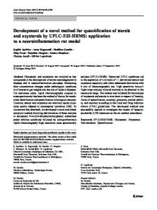
Figure 1. Schematic diagram of the electrode prepared by pulse electrodeposition.
A72
Electrochemical and Solid-State Letters, 7 共4兲 A71-A74 共2004兲
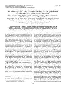
Figure 2. Backscattered electron image of the cross section of the membrane and electrode assembly.
Figure 4. The concentration distribution of Pt in the electrocatalyst layer of E-TEK anode and pulse electrodeposited cathode with a distance from the membrane.
pulse generator controlled both the pulse wave and the deposition current density. The amount of platinum electrodeposited on the electrode was estimated by the weight difference before and after electrodeposition. After electrodeposition, the electrodes were heated at 300°C in H2 gas for 2 h. And then, the electrocatalyzed electrode was impregnated with 5 wt % Nafion solution by spraying and then dried at 80°C for 2 h. The amount of Nafion loading was controlled to 0.8 mg/cm2 . The commercial E-TEK electrode 共singlesided ELAT 20 wt % Pt/C, 0.4 mg/cm2 ) was used as the anode for all tests. A total of 1.2 mg/cm2 Nafion solution was also applied to an E-TEK anode electrode by brushing and spraying. Nafionimpregnated electrodes and membrane 共Nafion 112兲 were bonded to form an MEA by hot pressing at 130°C for 3 min with a pressure of 140 atm. The reaction gases were supplied through a humidifier and a mass flow controller from hydrogen and oxygen tanks. The reactant gases flow according to cell performance 共1.5 stoic for H2 , 2 stoic for O2 ). The cell was operated under ambient pressure.
Figure 3. Platinum profile of the cross section of the membrane and electrode assembly in Fig. 2.
Figure 5. TEM image of Pt supported on carbon prepared by pulse electrodeposition, 共A兲 100000 magnitude 共B兲 400000 magnitude.
Electrochemical and Solid-State Letters, 7 共4兲 A71-A74 共2004兲
Figure 6. Comparison of MEA performance between pulse electrodeposited electrode and E-TEK electrode, H2 /O2 , 75°C, 1 atm.
Electron probe microanalysis 共EPMA, Cameca Instrument Incorporated, model MBX兲 and backscattering electron imaging were employed to measure the thickness of the electrocatalyst layer and to determine the concentration profile of Pt across the cross-sectioned MEA. The particle size of Pt prepared by pulse electrodeposition was determined by transmission electron microscopy 共TEM, Hitachi H-8000 model兲. Energy dispersive analysis by X-ray 共EDAX兲 coupled with an environment scanning electron microscope 共ESEM兲 was used to obtain the surface morphology of electrode and to determine the ratio of Pt in carbon. Results and Discussion Figure 1 illustrates the structure of the MEA prepared by a pulse electrodeposition technique. The deposition was carried out on uncatalyzed carbon substrate. The substrate consisted of a hydrophobic carbon cloth and a carbon paste layer placed on top of the carbon cloth. This whole layer acted as a gas diffusion layer 共GDL兲 in a conventional electrode. In the modified electrode a hydrophilic carbon layer was added to the substrate for reasons explained below. During electrodeposition, the thickness of the catalyst layer is controlled by the electrolyte penetration into the uncatalyzed carbon electrode. Since this phenomenon depends on the hydrophilic nature of the carbon electrode in case of an excessive hydrophilic nature of the layer, the electrolyte penetrates deeply into the carbon support and the resulting catalyst layer is thicker than desired. A strong hydrophobic layer results in a deposition within a very narrow layer thereby leading to a formation of dendrites. Thus, the optimized surface properties of the carbon support would lead to a desired particle size while reducing the catalyst layer thickness. To examine the exact structure of MEA, EPMA and energy dispersive X-ray 共EDX兲 spot analysis were performed. Figure 2 displays the backscattered electron image of the cross section of MEA consisting of an E-TEK anode and pulse deposited cathode. This image shows the five layers clearly and is useful for identifying the thickness of the membrane, catalyst layer, and gas diffusion electrode regions. The thickness of the Nafion 112 membrane is confirmed to be 50 m according to the scaling bar given in the bottom of the picture. The bright portion between the membrane and gas diffusion layer is associated with the presence of a heavier element such as Pt. Thus, these two light-colored bands on either side of the membrane show the thickness of the electrocatalyst layer on the anode and cathode side. The most striking aspect of this image is that the thickness of the pulse electrodeposited Pt electrocatalyst layer is only 5 m, which is ten times thinner than that of the E-TEK electrode. This is also confirmed from the concentration
A73
profile of Pt measured across a typical portion of the cross section of MEA by line scan using EPMA as shown in Fig. 3. It is useful here to distinguish between the two different approaches used to prepare the anode and cathode. The E-TEK anode was prepared using the conventional powder type approach where Pt/C mixture is dispersed and then loaded on the gas diffusion layer by spraying or coating. The cathode was prepared by the pulse electrodeposition approach by plating Pt on the blank carbon electrode and subsequently attaching it to the Nafion membrane. In Fig. 3, the pulse electrodeposited cathode exhibits a much higher intensity of Pt peak in the limited area near the membrane while the Pt line scan across the E-TEK anode electrode shows a relatively uniform intensity with a thickness of 50 m. Since the EPMA line profile has a broad resolution, to quantify the Pt ratio in the catalyst layer, the EDX spot analysis coupled with ESEM was also carried out for this cross section of the MEA. The results are shown in Fig. 4. According to this analysis, the Pt content in the cathode catalyst layer prepared by pulse electrodeposition decays with increasing distance from the membrane to the GDL. The Pt-to-carbon ratio at 1 m distance from the membrane is about 75 wt % and this value reduces to almost zero at a distance of 7 m from the membrane. In contrast, the E-TEK electrode shows about 20 wt % of Pt/C ratio distributed uniformly over the entire range of the catalyst layer. Both experimental and modeling studies of membrane electrodes indicate that active layers thicker than 10 m result in low catalyst utilization due to transport limitations of dissolved oxygen and protons in the ionomer.12 Figure 5 shows a typical TEM image of catalyst prepared by pulse electrodeposition. From the low magnitude TEM image noted as A, the dark spot indicates the presence of platinum. A scaling bar of 100 nm is given in the bottom of the image. According to this data, the particle size of carbon is 60-70 nm and the particle size of platinum seems to be a somewhat smaller. So it is a reasonable guess that a much smaller particle of platinum deposits on the surface of carbon and, for this reason, both particle sizes look similar. Next, the magnitude of TEM was increased to 400000. This TEM image 共Fig. 4B兲 shows that the previously observed large dark particles 共Fig. 4A兲 consist of smaller particles in rage of 3-4 nm. Also as shown in this figure, platinum exists in isolated places. Because only one side of carbon is exposed to the electrolyte, the platinum is deposited only on the exposed side of the particle. Therefore, Pt metal particles exist very close to the surface of the electrode and a thinner catalyst layer was obtained using the pulse electrodeposition approach. Figure 6 shows the performance of a PEMFC using two different types of cathode, one prepared using our selective deposition method and the other prepared using a conventional Pt/C powdertype method. The peak current density was optimized to be 200 mA/cm2 , on time 5 ms, off time 102.8 ms, and total charge density 11 C/cm2 . The results indicate that this method enables a selective deposition of Pt which leads to higher current densities at a given potential. For example, our electrode generates 0.33 A/cm2 current density at 0.8 V, whereas the commercial E-TEK electrode gives only 0.2 A/cm2 under the same conditions. Further, the pulse electrodeposited electrode uses only 62% of Pt used in the conventional electrode. The enhanced performance results from the improved electrode structure prepared by the pulse electrodeposition.
Conclusion An approach based on pulse electrodeposition was developed to prepare MEAs. Traditionally, pulse plating has been shown to produce deposits with lower grain sizes and particle sizes as compared to dc plating. For MEAs, this method showed that it has the potential to create Pt particles smaller than 5 nm while generating a high Pt/C ratio at the membrane-electrode interface. Further, this technique ensures that most of the platinum is in close contact with the membrane. The MEA prepared by this method showed higher performance with a smaller amount of Pt than conventional electrodes.
A74
Electrochemical and Solid-State Letters, 7 共4兲 A71-A74 共2004兲
The University of South Carolina assisted in meeting the publication costs of this article.
References 1. 2. 3. 4. 5.
K. B. Prater, J. Power Sources, 61, 105 共1996兲. S. G. Chalk, J. F. Miller, and F. W. Wagner, J. Power Sources, 86, 40 共2000兲. D. Rastler, J. Power Sources, 86, 34 共2000兲. G. P. Henry and A. A. Robert, U.S. Pat. 4,044,193 共1973兲. I. D. Raistrick, U.S. Pat. 4,876,115 共1990兲.
6. P. P. Dhar, J. Appl. Electrochem., 23, 32 共1993兲. 7. S. Hirano, J. Kim, and S. Srinivasan, Electrochim. Acta, 42, 1587 共1997兲. 8. E. J. Taylor, E. B. Anderson, and N. R. K. Vilambi, J. Electrochem. Soc., 139, L45 共1992兲. 9. O. Antoine and R. Durand, Electrochem. Solid-State Lett., 4, A55 共2001兲. 10. N. A. Qu, D. Zhu, K. C. Chan, and W. N. Lei, Surf. Coat. Technol., 168, 123 共2003兲. 11. E. Budevski, G. Staikov, and W. J. Lorenz, Electrochim. Acta, 45, 2559 共2000兲. 12. D. M. Bernardi and M. W. Verbrugge, AIChE J., 37, 1151 共1991兲.