Available online at www.sciencedirect.com
AASRI Procedia 3 (2012) 474 – 480
2012AASR RIConferenceonModeling,IdentificationandC Control
D Develop pment off Omni Direction D nal Mobiile Roboot Navigation System m using RFID foor Multiple Objeect a,1 b b.2 ,Norr SaidahbtM MohdZain ,Faridatu unbinti Mohhammad 1,2,,3Department of Mechatronicss Engineering, International I Isslamic Universiity Malaysia a Gombak, Kuuala Lumpur.
[email protected] m edu.my
M.M. Rasshid
c,3
Zain
Absttract Naviigation is an im mportant techniqque in the fieldd of mobile robotics. A major field of mobilee robot system is required to naviggate in unknow wn environmentts accurately. By B determining the positions and a selecting a motion controll of the robot, naviggation is fulfilleed through som me technique. Inn this paper, a modular m navigaation technique in relation witth signal from RFID D tags, and RFIID reader is developed. The main m idea is to test the ability of mobile roboot to navigate thhe location in indooor environmentts. The RFID reeader is mounteed on the mobile robot to com mmunicate withh the RFID tagss to determine robott’s position whiile the RFID taggs is are placedd at difference loocation . The position of mobiile robot is deteermined based on thhe location of RFID R tag. The actuator a will bee move accordinng to the angle between the roobot’s current ppositioned and the taarget tag. © Authors. Published © 2012 20012The Published d by ElsevierbyB.V. BElsevier B.V. Selection peer under responsibility of American Applied Science Research Seleectionand/or and/or p review peer review unnder responsibbility of Amer rican Applied Science Institute Reseearch Institute Keyw words: Omni roboot; Robot navigatiion; Reader; trannsponder
1. In ntroduction M Mobile robot navigation syystem has beecome an apppealing challeenge in both research andd production induustry. It is impportant due to its ability to navigate the location in un nknown enviroonment. Naviigation is the abiliity of a robott to determinee its own possition in its frame fr of referrence and then find its targget location. Navigation can be divided intoo three main fundamental which are seelf-localizationn, path planniing and map buildding.Self-locaalization meanns robot’s abillity to establissh its own po osition and oriientation withhin the frame of reeference. Pathh planning is effectively e ann extension off localization, in that it requuires the determination of the robot's r currentt position and a position of a goal locatioon while map building b can be b any notatioon describing locattions in the roobot frame of reference. r The aim of thhis project is to t develop Om mni Directionaal Robot Naviigation system m using RFID for multiple
2212-6716 © 2012 The Authors. Published by Elsevier B.V. Selection and/or peer review under responsibility of American Applied Science Research Institute doi:10.1016/j.aasri.2012.11.075
475
M.M. Rashid et al. / AASRI Procedia 3 (2012) 474 – 480
destinations. Both Omni robot and RFID system must be integrated to each other in the way of controlling the whole system. Omni robot is concerned due to its capability of mechanical manipulator and is capable of tethered and autonomous operation. It also focuses on RFID system which relies on navigation module using customized features of RFID technology. RFID system consists of tags, reader with antenna, and software. When an RFID reader scans the tag, a pulse of radio energy is sent out and the tag sends back the inventory control number. The objectives of this paper are; To design and develop Omni directional mobile robot that can move in indoor environment. To perform navigation by allocating identification tag at certain located area. To develop an efficient algorithm in providing better solution during navigation and to go particular target. 2. Methodology Following is the desired algorithm of mobile robot navigation system to navigate desired location of RFID tag by identifying the angle between the tags and the reader which is mounted on the mobile robot.Navigation elaborates the desired algorithm of mobile robot navigation system to navigate location of RFID tag by identifying the angle between the tags and the reader which is mounted on the mobile robot. Initially, the robot is pre-programmed with an order list of tag numbers in defining the position of the tag whereas the current target angle is determined by calculating current goal location. When the known ID is achieved, the target transponder is detected through the signal backscattered from all the tags within the communication range. The calculation after input received by the two antennas is recorded and computed using; (1) The mobile robot is then updating its headed by turn right and left and checked whether the angle between calculated and compass is reached. If not, it will turn until it found the correct angle. If yes, mobile robot is moving forward and detected more points. Mobile robot is then identifying current tag whether it is goal or not. If goal, it will stop. If not it will calculate current to goal angle and compare through continuous loop until it find the goal. 3. Omni Robot The Omni directional mechanismhave three axis and angle (x,y, ) movement abruptly in a two dimensional space, which ease to increase robot mobility and more keen access to limited spaces compared withconventional two wheel driven robot [1]. Yukawa et al. further explained that Omni-directional mechanism in the robot consists of four wheel units with a driving mechanism and a steering wheel mechanism. Since the four wheel units drive and steer independently, the position and direction of the mobile robot can be controlled with a high degree of accuracy [2]. Omni robot is becoming technically demanding for users in industrial and business sectors Figure 1. Many Omni robot navigation system products are appearing within medium and long term propositions that lead to development of variety technology advancement in the future. The most common and popular navigation techniques suggested in the state of the art generally fall under one of the following categories: dead-reckoning based, landmark-based, vision based, and behaviour technique based [3].
476
M.M. Rashid et al. / AASRI Procedia 3 (2012) 474 – 480
Figure 1: Two wheel mobile robot
A. Navigation The fundamental requirement for mobile robot through navigation is to estimate the position of the autonomous mobile robot. In earlier research, there are several methods used to estimating the robot position for example path planning, trajectory planning, algorithmic exploration and path execution with selflocalization. The goal of autonomous robot navigation is built for a system in which dynamically guide and control the mobile robot from its start positions to a predefined end position. According to the previous research, it is state that the robot successfully done their task if the robot can efficiently interpret the data from the sensor [4]. The first method used in previous research is self-localization. This method used the passive RFID tag where placed on the floor. The advantages of this method is that there does not required any information regarding the RFID tag except their ID number. Besides that, this method is used without need for the robot to stop temporarily to observe the RFID tag [5]. In addition, it is required to calculate the distance between the robot and the wall at the time robot passes the specific area to smoothly organize the movement of the robot. Other than that, by using the trajectory planning and path planning, we can estimate the position of the mobile robot. The differences between this method is that the presence of moving and avoiding the obstacle. The path planning used common approach by performing the specific algorithm to determine the shortest path. While for the trajectory planning in the presence of obstacle and find out the path and motion along the path. Furthermore, effective approach can be used by combining the dead reckoning and external sensing by using the metric model. By using the odometry, the approximate current pose can be obtaining but maintain the pose estimate [4].
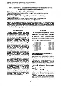
Figure 2: Active–Driving Wheel in Two Dimensions
B. Two wheel mobile robot Omni Directional robot locality is identical by 3-coordinates: position (x, y) and robot direction angle in an absolute frame. Therobot can mimic the waywhich [5-8] acquired from the current posture (x, y, ) in analignment space. Figure 2 shows an active driving two-wheeled robotwhereC is the centre ofmotion of the robot. The platformscentre of gravity of is at the origin (o), and (Vx, Vy)represents linear speed or tangential velocity, and w is the angular velocity. Here,r is the radius of the wheels, and D for azimuth length between the wheels [9]. Robot linear speed is defined by the absolute velocity (Vx, Vy) (Cartesian)in the platform
477
M.M. Rashid et al. / AASRI Procedia 3 (2012) 474 – 480
coordinate system at the origin (o), and w for the angular velocity [9-11]. Theta ( ) denotesthe heading angle of the turn in radians. The system is represented in (x, y) coordinate (and orientation) varying with respect to time. At any instant, the x the y coordinates of the robot’s centre point are changing based on its speed and orientation. While the time varying states, the physical laws governs the behaviour of the mobile robot but the system is time invariant. ….(1), (2), …..(3), (4) ….(5), (6), (7), (8), …..(9)
….(10)
…..(11)
Where: = right wheel angular velocity, = left wheel angular velocity,D = azimuth distance between the wheels, = wheel radius, = tangential velocity, or linear velocity, and = angular velocity, or steering velocity of the robot. The control inputs = ( , ) and our control outputs = (X, Y, ). Therefore, desired trajectory is X (t), Y (t), (t).However, it is difficult to study 3rd order and nonlinearsystem. Some nonlinear equations can be approximated by linear equations under certain conditions. Most of the system behaves like a linear system has a trajectory called the nominal trajectory. In this case chosen conditions for the system (12), (13) behaviour and modelled a linear system are followed. …….(14), (15), (16), ………(20)
(17),
(18)
……….(21)
(19)
(22)
Both wheels have the same initial speed. 4 Result Data from in table 1 are collected to check whether the tag is detected fast or not. This experiment is aimed to verify the counting number of passive tag that can be detected in 5.3 sec at a distance of 1cm.This passive tag can be detected at the range of 150mm.Each trial is tested to check detected tag during navigation. Each trial in figure 4 summarizes the path taken by mobile robot to reach its target.For trial 1 and 2, only five tag is detected, while trial 3, 4, and 6, six tag is detected and both trial 4 and 5, seven tag is detected. This experiment results in random decision path which will be taken by each trial. Table 1: Numbers of ID tag detect in 5.3 sec
Trial vs Tag Detected
Trial 1 2 3 4 5
Tag Detected(name) Red Stop Blue Blue black Dark blue
Count 93 79 82 84 88
Figure 3: ID detection for each trial
Several trials as shown in table 2 have been conducted to evaluate time elapse for the mobile robot to reach the goal from the starting point. Each of tag has been named accordingly based on the ID tag positions.
478
M.M. Rashid et al. / AASRI Procedia 3 (2012) 474 – 480
Accoording to figuure 5, mobile robot navigaation is alwayys updating itss angle until it finds the goal. Current headding can be caalculated usingg; …..(23) ,
…… …(24),
… (25)
To get g exact rotatiion of mobile robot; …… ….(26)
(27)
…….(28)
Figurre 4: Time elapse to reach goal possition
a) Testing and Evaluation To verify whhether the moobile robot ism moving accorrdingly and acchieved the objectives, o sevveral testing needd to be considdered literallyy. At first, proogramming innstruction is uploaded u to thhe microcontrooller to turn rightt if compass angle is greaater than headding, turn leftt if compass angle is less than headingg, and move forw ward when com mpass angle iss equal to headding angle. Hoowever, the ro obot doesn’t move m accordinngly because the probability p forr the robot to move m forwardd by ±1 is imppossible. Then n, the instructioon is adjustedd by ±3. The results dooes not accuraately headed the t mobile robbot to the goaal, but in ideall condition thee calculation has proved p that evverything should be in the right track if the procedurees is follow acccordingly. Thhis might be due to late reactioon of RFID anntenna to read the tag at timee it reached taag. Moreover, the programm ming is quite longg and thus causes delay for looping. l Durinng the processs, the antenna could not reaad tag accordinngly when it headded to the tagg, instead thee antenna coils must be att the centre of o the tag so that it can rread the tag simuultaneously. Some S readingg is missed duuring navigattion process as a this probleem occurs. Thhis problem happpens due to leess read range of the reader. Mobile roobot somehow w didn’t movee to the centrre of the tag althoough it reacheed the tag point. Trials show that possibbility to reducee error is wheen the displacement taken by thhe mobile robot is closed too the ideal dispplacement. 5. Conclusion Basic developpment of this robot has beeen constructedd and tested. Generally, G the objectives off this project havee been met sinnce the aims are a to developp and design thhe Omni mob bile robot usedd for navigatioon in indoor enviironment. Thee result shows that the proototype modeel of mobile robot r with RF FID system iss able to be
M.M. Rashid et al. / AASRI Procedia 3 (2012) 474 – 480
applied in real situation. In addition, the position of the mobile robot is determined based on information provided by the tag and the orientation information by the compass while the angle between the robot’s current direction and the target tag is used to provide action to the actuators.Intelligent controller might be applied to the system to reduce an error. Moreover, suitable sensor such as ultrasonic sensor might be used to avoid obstacles in indoor environment.
Figure 5: Navigation path
References [1] San, K. and Dong H. K., (2007). A design and implementation of moving object tracking system for omni-directional robot, International Conference on Control, Automation and Systems 2007 Oct. 17-20, 2007 in COEX, Seoul, Korea, 1790-1793. [2] Yukawa, T., Matsumoto, T., Okano, H., & Hosoya, O. (2006). Development of an omni-directional mobile robot with two or more cameras and navigation based on cell map information, 32nd Annual Conference onIEEE Industrial Electronics, IECON 2006, 213-218. [3] Miah, M.S., & Gueaib, W. (2007). An RFID-Based Robot Navigation System with a Customized RFID Tag Architecture, 18, 25-30. [4] Feng Lu (2004), Shape Registration using optimization for mobile robot navigation, 1-153. [5] Kimuro, Y., Takarabe, S., & Hasegawa, T.(2007). Machine Learning Approach to Self-Localization of Mobile Robot using RFID Tag,Advanced intelligent mechatronics, 2007 IEEE/ASME international conference,1-6. [6] Martinussen, E. S., and Arnall, T. (2009). Designing with RFID, Proceedings of the Third International Conference on Tangible and Embedded Interaction (TEI'09), Feb 16-18 2009, Cambridge, UK, 343-350. [7] Miah, M.S., & Gueaib, W. (2007), Intelligent Parallel Parking of a Car- Like Mobile Road Using RFID Technology, International Workshop on Robotic and Sensors Environments, 1-6. [8] Hae, D.C., Sibum, J., Heejae, J., & Sang, W. A. (2004). Using RFID for Accurate Positioning:Journal of Global Positioning Systems, 3, 32-39. [9] Nuha.N (2005), H-Infinity Control Of An Autonomous Mobile Robot, 1-85. [10] Finkenzeller.K (2003), RFID Handbook: Fundamentals and Applications in Contactless Smart Cards and Identification(2nd Ed.),Germany, John Wiley & Sons Ltd.
479
480
M.M. Rashid et al. / AASRI Procedia 3 (2012) 474 – 480
[11] Heesung Chae & Sangik Na (2007). Mobile Robot Navigation using RFID and Vision Sensor. 2007 International Symposium on Information Technology Convergence, 52-57.