Abstractâ A robotic device with haptic, tactile, and ultrasound capabilities ... Orlando, Florida - May 2006 ... have been used in rehabilitation and medical diagnostics [12]. ... design, based on a single degree-of- freedom, which requires a.
Proceedings of the 2006 IEEE International Conference on Robotics and Automation Orlando, Florida - May 2006
Development of Supermedia Interface for Telediagnostics of Breast Pathology Nandagopal S. Methil† , Yantao Shen∗ , Danyu zhu∗∗ , Craig A. Pomeroy∗ , Ranjan Mukherjee† Ning Xi∗ and Matt Mutka∗∗ †
Dept. of Mechanical Engineering Dept. of Electrical and Computer Engineering ∗∗ Dept. of Computer Science and Engineering Michigan State University East Lansing, MI 48824, USA {methilsu, shenya, zhudanyu, pomeroy3, mukherji, xin, mutka}@egr.msu.edu ∗
and ultrasound data to the physician at the remote location via the Internet. The haptic information will be rendered in its original form by the haptic device to generate the feeling of the force applied during diagnostics. The tactile information will be rendered in the form of an image, similar to the ultrasound image, as well as in the form of electrical pulses at the three examination fingers of the physicians hand. This will provide the sensation of touch that will enable the physician to detect abnormalities of the breast tissue. Our telediagnostics system will fill the need for clinical breast exam for women in remote areas who do not have convenient access to a physician. The ultimate goal of our research is to reduce the morbidity and mortality of women diagnosed with breast cancer by early detection of the disease. The application of robotic systems in medicine has seen a rapid growth in the last few years. Specifically, the use of robots in surgery has increased significantly [5], both in open and minimal invasive surgery (MIS) [6]. They include the stereotactic robot positioner [7], the ROBODOC orthopedic surgery system, and the robot used for transurethral resection of the prostate [8]. A Steady-Hand robot was also developed to extend a humans ability to perform small-scale manipulation in surgical operation [9]. Many researcher, such as [10], have envisioned the potential advantages of teleoperation in medicine. Examples include a surgeon-machine interface for teleoperated microsurgery [11], a finger-sized manipulator for corneal transplant surgery [12], a three-axis manipulator for cutting [13], and a shared-control approach to minimally invasive telesurgical training and collaboration [14]. In most existing robotic surgical procedures, surgeons do not have haptic and tactile feedback from the surgical site [15]. As a result, there is an extended learning curve for a surgeon, specially, for those involved in remote operation [16]. It is highly desirable to design a telesurgical system in which the surgeon can see and feel while he is operating. Shimoga, et al. [17] developed an advanced telesurgery system with touch and force reflection using dextrous anthropomorphic multifingered hands. In the last decade many such hands have been developed
Abstract— A robotic device with haptic, tactile, and ultrasound capabilities, which can acquire and render information of breast pathology was developed. A physician interface that can examine the human breast remotely and accurately, using such a robotic device was also developed. Such a robotic device can be used to do screening or focused breast exams for patients in remote areas without convenient access to physicians. Because of in situ ultrasound imaging, examination by the robotic device may prove to be more accurate than examination by the physicians own hand. In addition, the robotic device can also be used to train healthcare professionals in breast pathology.
I. I NTRODUCTION In 2005, over 200,000 women will be diagnosed with breast cancer and 40,000 will die from it [1]. Physical diagnosis of breast pathology is very important since mammography diagnoses only 85cases [2]. Women living in remote areas may have no or limited access to regular screening physical examinations. A method to accomplish breast examination with the physician in a remote location will improve medical care and potentially save lives. Existing technology to diagnose breast pathology includes mammography [3] and ultrasound [4] to complement the physical examination. The techniques of thermography and Magnetic Resonance Imaging have not been proven reliable for clinical use. Even with all the imaging technologies listed above, breast cancer is sometimes diagnosed only by physical examination. We propose to develop a robotic system that can duplicate physical examination of the breast along with ultrasound imaging. To our knowledge, no similar device exists or has been proposed by other researchers. By incorporating an ultrasound probe in the palm of our multifunctional hand, we will be able to add the dimension of seeing into the breast while receiving simultaneous tactile feedback. This has the potential to surpass the actual physical exam. More importantly, this robotic device will be teleoperated by a physician at a different location over the Internet. Abnormalities in breast tissue will be detected by tactile sensors embedded in the multifunctional hand. This sensor data will be transmitted along with audio, video, haptic
0-7803-9505-0/06/$20.00 ©2006 IEEE
3911
the ultrasound probe, which enables ultrasound imaging and clinical diagnosis simultaneously with tactile sensing. The use of both tactile and ultrasound sensors will allow interactive palpation and improve the chances of tumor detection. The Wrist portion of the hand is attached to a force/torque sensor, which is used to provide haptic feedback to the physician such that he/she can moderate the forces applied during diagnostics. A salient feature of the multifunctional hand is its simplistic design, based on a single degree-of- freedom, which requires a single actuator/motor. This is achieved by coupling the motion
[18],[19], but the major problems in the development of multifingered hands have been tactile sensing and haptic/force perception [20, 21]. Apart from surgery, multifingered hands have been used in rehabilitation and medical diagnostics [12]. In [22], a robot arm is used for positioning an ultrasound probe for diagnostics. Brady, et al. [23] used a free-hand technique to generate a 3-D image from a sequence of 2D image slices of the breast to estimate breast deformation. One of the important issues in teleoperation is to design a human-robot interface that enables operators to control the robot effectively and feel real-time forces of interactions between the robot and the environment [24]. Tremendous efforts have been made to design such interfaces in the last decade [25]. However, these systems do not provide information about the physical contact between the robot and its environment. The contact information, which is comprised of haptic and tactile components, is very important in telediagnostics. Internetbased teleoperations have been introduced over the past several years. Many researchers have attempted to use force reflection for haptic feedback in teleoperations [26].
ultrasound probe
embedded tactile sensors
camera
Wrist
Palm Fingers
motor for hand articulation breast model
II. SYSTEM OBJECTIVE AND OVERVIEW
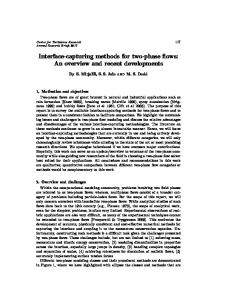
Fig. 2.
The system developed is shown in Fig.1. and its description is provided in the sequel. In the next section we provide preliminary results obtained using the system. The system in figure 2 is comprised of: (a) a multifunctional hand attached to a robot manipulator, (b) a tactile sensory unit attached to the multifunctional hand, (c) a haptic device for position control of the robot and haptic and tactile feedback, (d) an electrotactile array for rendering the tactile information, In the above list, items (a), (b) pertain to hardware on the patient side, items (c), (d) pertain to hardware on the physician side. An architecture for overall system integration, and a software that enables network management and control will be discussed in future papers. In the next section, we discuss the research and development work in each of these subcomponents.
Illustration of the assembly of the robot hand.
of the joints between the Wrist and Palm and the Palm and Fingers by the belt drive (not visible in figure 2). The coupled motion of the two joints maintains the Fingers parallel to the Wrist at all times while enabling the Palm to articulate to change the angle of incidence of the ultrasound probe. Currently, the Palm can be articulated in excess of 90 degrees. The Fingers have length, width, and thickness of 50, 60, and 10 mm, respectively. Similarly, the palm has dimensions of 70, 60, and 20 mm, respectively. The Wrist houses the motor and a worm-gear that transmits the motion from the motor to the belt drive, while preventing back rotation. The hand in figure 3 was designed to apply forces up to 50 N. For future improvisation we will quantify the force used by physicians during breast exams using silicone breast models such that the hand can be designed optimally by eliminating conservatism. The multifunctional hand was attached to an RX60 Staubli robot arm (see figure 1). The Staubli robot has 6 degrees-offreedom and this provided sufficient maneuverability required for conducting simple experiments that reflect the exploratory nature of our work. The experiments are briefly discussed in the next section. B. Tactile sensor
Fig. 1.
The tactile sensor, embedded in the multifunctional hand, operates on the principle of optical total internal reflection. The sensor consists of an elastic membrane, an optic-waveguide glass plate (or transparent flexible rubber plate), a high resolution micro CCD/CMOS camera, and a light source, as shown in figure 3. Its design and mechanism are described next. The light from a micro-light source is injected into the opticwaveguide from its edge. Since the index of reflection of air on both sides of the optic-waveguide is smaller than that of the optic-waveguide, most of the light is reflected internally
System Overview
III. M ULTIFUNCTIONAL HAND . A. Hand Design The multifunctional hand, shown separately in figure 2, is composed of three components, namely, (i) Fingers, (ii) Palm, and (iii) Wrist. The Fingers hold the tactile sensory unit that can detect breast tissue abnormalities. The Palm supports
3912
Optic-waveguide cover
stimulation on the three examination fingers on the physicians hand when breast tissue abnormalities are detected. In order to address the above mentioned objectives, we designed a six degree-of-freedom haptic device, with three degrees-of-freedom, each in translation and rotation. The translational degrees-of-freedom are achieved using rack and pinion mechanisms, as shown in figure 4 . For each rack, the corresponding pinion is mounted on a slider block that slides relative to the rack. The racks for the three translational degrees-of-freedom are placed in mutually orthogonal directions and kinematically appended in a chain-like fashion to form the complete translational frame. Each pinion in the frame is driven by a separate motor with encoder. The three encoders provide measurement of the translational coordinates.
Organic glass support
Lens group Optical fiber image cable
Elastic membrane
CCD device
Light source Computer monitor
Fig. 3.
Image card
Principle sketch of the tactile sensor. encoder circular element
flat element
into the optic-waveguide plate and no light is sent to the camera. When the tactile sensor touches an object, the elastic membrane comes in close contact with the optic-waveguide. As a result, diffused reflection occurs, thus forming a tactile image of the touched area, which is captured by the camera. Notice that if the transparent rubber plate is used as the optic-waveguide, when the tactile sensor contacts the object, the amount of the rubber plate deformation depends on the stiffness of the contact object. Generally, when it touches a soft object, the deformation of the waveguide plate is smaller than when it contacts a hard one. This results in different light intensities of the tactile images due to different deformations of the waveguide. Therefore, the rubber waveguide plate can serve as a mechanical filter to classify the rigidity of touched objects. This is suitable for detection of hard tumors surrounded by soft tissue, as in the case of breast tumors.
force/torque sensor
mount for tactile array
encoder motor with encoder
motor with encoder
y axis rack pinion
Fig. 4.
x axis
Surgeon Interface
The rotational frame consists of several elements. At the base is the circular guide with two slider blocks. A flat element running along the diameter to the circle is connected to the two sliders. This holds the sliders on diametrically opposite sides and enables them to rotate along the circle. The encoder fixed to the top of the circular guide measures the rotation of the sliders using a pulley and cable mechanism. A rotational joint allows the flat element to rotate relative to the sliders and the rotation is measured by an encoder attached to one of the two sliders. Finally, the mount for the electrotactile array is attached to an adapter capable of rotating relative to the flat element. This rotating joint also has an encoder. The three encoders together measure the orientation of the rotating frame. The orientation measurement and the translation measurement is used to command the motion of the robot manipulator such that the multifunctional hand replicates the motion of the physicians hand. The three motors in the translational frame of the haptic device provide force feedback to the physician. The motors assist the physician in translating his hand and commanding the motion of the multifunctional hand or resist the motion of the physicians hand depending on whether the force applied by the physician is greater than the force applied to the
IV. 6 DOF SURGEON INTERFACE A. Design In order to conduct physical examination of the breast from a remote location, the physician would need to place the multifunctional hand at desired locations of the breast, control the motion of hand (such as motion in circular patterns) while applying a certain level of force needed to detect breast tissue abnormalities. To this end, we designed and fabricated the device shown in figures 2 and 4. The haptic device has two main functionalities, namely, measure both the translation and rotation of the physicians hand and provide both haptic and tactile feedback to the physician. The motion of the physicians hand is measured with the purpose that the multifunctional hand can be commanded to move in the same manner as the physicians hand. The haptic device also houses motors that resist the motion of the physicians hand so as to provide force feedback to the physician. This feedback is provided such that the physician is cognizant and can moderate the forces being applied by the multifunctional hand on the breast. The haptic device also houses the tactile rendering device or the electrotactile array. This device will provide electrical
3913
Fh , Fr be the reaction force obtained from the breast surface as the robotic hand presses against it on the other end and Fm is the control input in the form of motor torque on the motor driving the selected axis (Z) of the haptic device. Also, let us use notations ˆb = b/M, Fˆh = Fh /M and Fˆm = Fm /M , Where M is the mass of the link and b is the damping coefficient. The dynamics of the vertical axis of the Haptic device can be expressed as
multifunctional hand on the patients breast. The force applied by the physician is measured by a force/torque sensor, which is placed below the mount for the electrotactile array.
Mx ¨h = −bx˙ h + Fh + Fm + M g
Fig. 5.
(1)
The M g term appears however only for the vertical axis and does not appear at the two horizontal axes. We would like the system comprising of the controller and haptic device to follow the following dynamic equation:
Electrotactile array
B. Electrotactile Haptic Array The electrotactile array is a display device that enables a human operator to feel contact of a robot hand with a touched object. We have designed an electrotactile array that can rapidly evoke touch sensations at the operators fingertip. It consists of a signal transformer, a stimulus pulse signal generator circuits, and an electrode array device. The contact image detected by the tactile sensors are first separated into smaller areas corresponding to the electrode array. They are then transformed as triggers to select the stimulus pulse signals (utilizing a booster circuit) for each element electrode element of the array. In order to display the realistic feeling of touch on the basis of tactile texture images, the selected stimulus pulse signals will exert multipoint excitation in at the operators fingertip via the electrode array in real time. To ensure safety, it was necessary to include a preprotective circuit as a buffer. The tactile array corresponding to three tactile sensors on the multifunctional hand are shown in figure 5. The array for each finger (index, middle, and ring) has 98 stimulation electrodes within an area range of 12mm x 25mm. The size of each electrode was chosen to be approximately 1 mm2 .
x¨h = Fh − Fr
Fh
+ _
Fh- F r Haptic device controller
Fm
Fr
Fig. 7.
Haptic device
Xh
R obot Controller
(2)
R obotic arm and hand
Xr
B reast stiffness
Block Diagram of System.
This will mean that the system has an acceleration that is equal to the difference between the forces that the physician applies and the reaction force that the robot hand experiences on the other end and hence will provide the exact force feedback on to the physician’s hands. However we will include a damping term ˆb and stiffness constant kˆ to guarantee stability. Thus the desired dynamical equation is now ˆ h = Fh − Fr x ¨h + ˆbx˙ h + kx
(3)
Eq.(3) can be written in state space form with x1 = xh and x2 = x˙ h as x˙ 1 x˙ 2
= =
x2 ˆ 1 + Fh − Fr −ˆbx2 − kx
(4) (5)
Theorem 1 For the system given in Eq. (1) the control law, ˆ 1 Fˆm = −Fˆh + Fh − Fr − g − kx Fig. 6.
(6)
Illustration of Tactile Pattern Identification
results in the desired dynamics given by Eqs.(4) and (5). Furthermore the the equilibrium point, (x1 , x2 ) = (0, 0), of the system described by Eqs.(4) and (5) is asymptotically stable.
C. Dynamics and Force Control of the Surgeon Interface Consider one of the axes (vertical Z axis) of the haptic device above detailed. Let the force applied by the operator be
Proof:
3914
where −kˆ + Kp = K. The real part of all the eigen values of the A matrix in the above system of state equations are negative. Hence the A matrix is hurwitz and the equilibrium points are asymptotically stable
The first part of the theorem is easy to prove since substitution of the control law, Eq. (6), in Eq. (1), results in Eqs.(4) and (5). To prove asymptotic stability of this equation, consider the storage function 1 kˆ (7) V = x21 + x22 2 2 Differentiating V and substituting for x˙ 2 from Eq. (5) we get V˙ = −ˆbx22 + (Fh − Fr )x2
VI. EXPERIMENTS USING ARTIFICIAL BREAST The Surgeon interface and robotic system in figure 1 were interfaced with the physician side and patient-side computers, respectively. The two computers were connected over the Local Area Network. Preliminary experiments were then conducted to (a) move the robot arm using the haptic device, and (b) feel haptic and tactile sensory feedback at the haptic device corresponding to force and tactile information obtained from silicone breast models (see figure 8,9,10).
(8)
Where (Fh −Fr ) is the input to the system. This shows that the system is output strictly passive with output is x2 . Since this is the regulated output, and since it is zero state observable, it is proved that the equilibrium is strictly stable [27]. V. OVERALL S YSTEM C HARACTERISTICS The overall system control design has detailed in the block diagram. The input to the overall system is Fh , which is force provided into the haptic device by the operator. The output of the system is the robot motion in terms of xr . The block diagram has been manipulated so as to look like a regular feedback system. Another point to note is that the breast surface has been modelled as a spring with stiffness Ke . The reaction force obtained at the breast surface is fed into the controller at the haptic device. The dynamic equations of the haptic device have already been discussed. Applying nonlinear feedback cancellation and then applying a standard linear control for the robot, we get the dynamic equations of the robot to be, ¨h + Kv (x˙ h − x˙ r ) + Kp (xh − xr ) x ¨r = x
(A1)
(B1)
Fig. 8.
Tactile and Ultrasound images (A1 and B1)
(9)
State space representation of the entire system with x1 = xh , x2 = x˙ h , x3 = xr and x4 = x˙ r will be x˙ 1 x˙ 2
= =
x˙ 3 x˙ 4
= =
x2 ˆ 1 − ˆb x2 − Ke x3 + Fh −kx
(10) (11)
x4 (12) ˆ ˆ −kx1 − b x2 − Ke x3 + Kv (x2 − x4 ) + Kp (x1 − x3 ) + Fh (13)
(A2)
here Fr = Ke x3 as mentioned before Theorem 2 (B2)
Consider the Eqs. (10) to (13), the equilibrium point (x1 , x2 , x3 , x4 ) = (0, 0, 0, 0), is asymptotically stable.
Fig. 9.
Proof The above equations can be written in matrix form as ⎡ ⎤ ⎤ ⎡ 0 1 0 0 0 ˆb ⎢ 1 ⎥ ⎥ ⎢ −kˆ 0 − −K e ⎥ X + ⎢ ⎥ Fh X˙ = ⎢ ⎣ 0 ⎦ ⎣ 0 0 0 1 ⎦ ˆ 1 K Kv − b −Kp − Ke −Kv (14)
Tactile and Ultrasound images (A2 and B2)
A. Operation of Multifunctional hand Tests were conducted on silicone breast models (made by Milex Co.). The first experimental result, shown in figure 8(A1), is the tactile image from the sensor when the hand applies pressure on a breast model without any tumors. The corresponding ultrasound image is given in figure 8(B1). Figure 9(A2) shows the tactile image of a single, large tumor;
3915
[4] Stavros AT, Thickman D, Rapp CL, Dennis M, Parker SH, Sisney GA, Solid breast nodules: Use of sonography to distinguish between benign and malignant lesions. Radiology 196:123-134, 1995. [5] P. Dario, E. Guglielmelli, B. Allotta, and M. C. Carrozza. Robotics for medical applications. IEEE Robotics and Automation Magazine, vol. 3, no. 3, pp. 4456, 1996. [6] H. Kang and J. T. Wen. Robotic Assistants Aid Surgeons During Minimally Invasive Procedures. IEEE Engineering in Medicine and Biology Magazine, pp. 94102, Jan/Feb 2001. [7] K. Masamune, M. Sonderegger, H. Isek, K. Takakura, M. Suzuki, and T. Dohi. Robots for stereotactic neurosurgery. Advanced Robotics, vol. 10, no. 4, pp. 391401, 1996. [8] W. S. Ng, B. L. Davies, R. D. Hibberd, and A. G. Timoney. Robotic surgery. IEEE Engineering in Medicine and Biology Magazine, vol. 12, no. 1, pp. 120125, Mar 1993. [9] R. Taylor, A. Barnes, R. Kumar, P. Gupta, Z. Wang, P. Jensen, L Whitcomb, E. deJuan, D. Stoianovica, and L. Kavoussa, A SteadyHand Robotic System for Microsurgical Augmentation. Submitted to MICCAI99. [10] J. W. Hill and J. F. Jensen. Telepresence technology in medicine: principles and applications. Proceedings of the IEEE, vol. 86, no. 3, pp. 569580, Mar 1998. [11] S. Charles, R. E. Williams, and B. Hamel. Design of a surgeon-machine interface for teleoperated microsurgery. Proceedings of IEEE Engineering in Medicine and Biology, 11th Ann. international conference, pp. 883884, 1989. [12] M. Sabatini, M. Bergamasco, and P. Dario. Force feedback-based telemicromanipulation for robot surgery on soft tissues. Proceedings of IEEE Engineering in Medicine and Biology, 11th Ann. international conference, pp. 890891, 1989. [13] S. Nakaura, T. Hoshino, H. Tokura, and M. Yoshikawa. Development of a bilateral manipulator for surgical operationCharacteristics of the developed manipulator. Journal of Japan society of precise engineering, vol. 62, no. 10, pp. 14491453, 1996. [14] Wang, Y., Ghodoussi, M., Uecker, D., Wright, J., Mangaser, A., and Mukherjee, R., Minimally Invasive Surgical Training Using Robotics and Tele-Collaboration, US Patent 6,852,107, February 8, 2005. [15] G. Madhavan, S. Thanikachalam, I. Krukenkamp, and A. Saltman. Robotic surgeons IEEE potentials, pp. 47, Aug./Sept. 2002 [16] S. Charles. Dexterity enhancement for surgery. Proceedings of 1st international symp. on medical robotics and computer assisted surgery, pp. 145160, 1994. [17] K. B. Shimoga and P. K. Khosla. Touch and force reflection for telepresence surgery. Proceedings of the 16th Annual International Conference of the IEEE Engineering in Medicine and Biology Society, pp. 10491050, 1994. [18] H. Liu, J. Butterfass, S. Knoch, P. Meusel, and G. Hirzinger. Multisensory articulated hand. IEEE Control System Magazine, vol. 19, pp. 4754, 1999. [19] L. R. Lin and H. P. Huang. Integrating fuzzy control of the dexterous National Taiwan University (NTU) hand. IEEE/ASME Transactions on Mechatronics, vol. 1, pp. 216229, 1996. [20] R. S. Fearing. Tactile sensing mechanisms. International Journal on Robotics Research, vol. 9, no. 3, pp. 323, 1990. [21] S. A. Stansfield. A Haptic System for a Multifingered Hand. Proceedings of IEEE International Conference on Robotics and Automation, pp. 658663, 1991. [22] P. Abolmasesumi, S. E. Salcudean, and W. H. Zhu. Visual Servoing for Robot-assisted Diagnostic Ultrasound. Proceedings of the 22nd Annual EMBS International Conference, pp. 25322535, 2000. [23] G. Xiao, J. M. Brady, J. A. Noble, M. Burcher, and R. English. Nonrigid Registration of 3-D Free-Hand Ultrasound Image of the Breast. IEEE Transactions on Medical Imaging, vol. 21, no. 4, 2002. [24] Y. H. Liu, P. C. Lam, D. Z. Li and Y. Y. Leung Martin. Integrated Sensing, Task Teaching, and Control for Dextrous Manipulation of Multifingered Robot Hands. The 14th World Congress of IFAC, 1999. [25] K. Taylor, B. Dalton and J. Trevelyan. Web-based Telerobotics. Robotica, Vol. 17, pp. 4957, 1999. [26] Gunter Niemeyer and Jean -Jacques E. Slotine, Towards Force - Reflecting Teleoperation Over the Internet, Proceedings of the IEEE International Conference on Robotics and Automation, Leuven, Belgium, May 1998 [27] Khalil, H. 2002, Nonlinear Systems , 3nd Ed. Prentice Hall, upper Saddle River, NJ.
(A3)
(B3)
Fig. 10.
Tactile and Ultrasound images (A3 and B3)
the bright area corresponds to the convex surface of the tumor and the dark area denotes the concave part. The corresponding ultrasound image is given in figure 9(B2). The tactile image of multiple tumors is shown in figure 10(A3) and the corresponding ultrasound image is given in figure 10(B3). All experiments demonstrate high performance of the Multifunctional hand and its sensors. B. Operation of the Surgeon Interface We conducted experiments to explore the perception at the fingertip provided by an electrotactile array, which follows a tactile image in real-time. Figure 6 shows the elements of electrotactile arrays providing stimulus corresponding to the tactile images to the left. In these experiment, the tactile images could be deciphered from the electrical stimulus without viewing the images. The force feedback device was made to accelerate according to the difference in the F/T sensor data obtained. VII. C ONCLUSION We designed and developed a new robotic hand for telerobotic operation of a physical breast examination by palpation. The robot hand was incorporated with the newly developed high resolution tactile sensors. The integrated system are capable to detect high resolution tactile images of tumors when it tested on an artificial breast model. These tactile images can be further efficiently transformed into electrotactile excitation which can then be felt by the operator/examiner through the newly developed electrotactile haptic array device. Experimental results show the potential of this new technology to ultimately provide a major step towards the development of more reliable medical tele-diagnostic systems. R EFERENCES [1] American Cancer Society Statistics. American Cancer Society Home page, http://www.cancer.org. [2] Smart CR, Hendrick RE, Rutledge JH, Smith RA, Benefit of mammography screening in women ages 40 to 49 years. Cancer 75:1619-1626, 1995. [3] Kerlikowske K, Grady D, Rubin SM, Kagawa M, Grady D., Efficacy of screening mammography. A metaanalysis. JAMA 273:149-154, 1995.
3916