dedicated 3-MV Pelletron tandem AMS facility. As a new tool .... The underlying evaluation programs, running on a dedicated server computer under Linux, use.
DEVELOPMENTS TOWARDS A FULLY AUTOMATED AMS SYSTEM P. Steier, S. Puchegger, R. Golser, W. Kutschera, A. Priller, W. Rom, A. Wallner, E. Wild Vienna Environmental Research Accelerator, Institut für Radiumforschung und Kernphysik, Universität Wien, Währinger Straße 17, A-1090 Vienna, Austria Abstract The possibilities of computer-assisted and automated AMS (Accelerator Mass Spectrometry) measurements were explored. The goal of these efforts is to develop fully automated procedures for "routine" measurements at the Vienna Environmental Research Accelerator (VERA), a dedicated 3-MV Pelletron tandem AMS facility. As a new tool for automatic tuning of the ion optics we developed a multidimensional optimization algorithm robust to noise, which was applied for 14 C and 10 Be. The actual isotope ratio measurements are performed in a fully automated fashion and do not require the presence of an operator. Incoming data are evaluated online and the results can be accessed via Internet. The system was used for 14 C, 10 Be, 26 Al, and 129 I measurements. PACS: 07.05.Dz; 02.60.Pn; 29.27.Eg; 29.30.-h Keywords: Automation; AMS; Optimization algorithm; Noisy data; Beam tuning Introduction A prerequisite for a reliable isotope ratio measurement is a careful accelerator tuning. “Retuning” of VERA [1] for a routine measurement starts from a "golden” setup. This setup guarantees that after adaptation of a small set of parameters the measurement will yield high quality data. In our understanding this retuning does not improve the golden setup, it only adapts it to changed machine conditions. Some critical parameters (mainly focussing elements) are not touched. Our golden setups for 14 C and 26 Al were originally found by time consuming manual exploration. We never were sure that the golden setup could not be further improved by a certain, simultaneous change of many parameters. Moreover, simply scaling an existing golden setup to another ion species did not work. Recently we explored general purpose multidimensional optimization algorithms as an alternative way to find golden setups. These algorithms can work in a fully automated fashion. Attempts at automated accelerator tuning were made at various facilities, including designs which are general in scope and applicable to a wide range of accelerator facilities [2]. These designs implement and combine various advanced information technologies such as expert systems, neural networks, and fuzzy logic. However, on a lower level, improved conventional algorithms to optimize certain beam diagnostic parameters will be an important tool even for these advanced designs. Existing optimization algorithms used in numerical mathematics generally have problems with the inherent noise of the data. For routine measurements (e.g. 14 C) we have reached a high level of automation. The retuning described above is only assisted by the computer (i.e. presence of an operator is required), whereas the actual isotope ratio measurements are performed fully automated. The automatic data evaluation software calculates diagnostic marks to allow early detection of malfunctions.
1
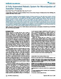
Automatic tuning In AMS one radioisotope of interest and (at least) one stable isotope for normalization are measured. The transmission of both ion beams influences the measured isotope ratio. To compensate for transmission differences a standard material is needed as a reference. The accuracy of the AMS measurement depends on the reproducibility between the unknown and the reference sample. Unavoidable differences in the geometry of the samples serving as a target in the Cs-sputter source induce changes of the beam geometry and consequently of the transmission through every aperture where parts of the beam are lost. Generally a reduction of the losses will increase the accuracy of the results [3]. Careful accelerator tuning is most crucial if high precision is needed (14 C) or if high mass resolution requires operation with narrow slits (heavy ions). Our new optimization algorithm was especially useful for finding golden setups for our negativeion injector [1], where many elements have to be tuned with only a small number of diagnostic parameters available. The algorithm allows to maximize (or minimize) any beam property which is accessible by the computer (e.g. a Faraday cup current or the accelerator transmission). We call this parameter the "optimization target" f, which is optimized by adjusting the N machine parameters p1 ,...,pN (steerer voltages, magnet fields, etc.). A parameter-manipulation layer communicates with the hardware and hides machine-dependent details. It displays the underlying hardware as a function f(p1 ,...,pN) to a second layer, where generally formulated algorithms control the optimization process. The difference between f(p1 ,...,pN) and a mathematical function is the inherent measurement noise. The parameter-manipulation layer tries to filter out glitches, and it may improve the data by averaging. However, the algorithm itself must be robust against noise and a limited rate of corrupted measurements. To find the optimum in a large N-dimensional parameter space within reasonable time, an algorithm has to “learn” about the cross-dependencies of the various parameters. Mathematically this corresponds to finding so called "conjugate directions" which, to some degree, describe advantageous simultaneous changes of many parameters. For our injector one such conjugate direction corresponds to the instruction: "If you loose transmission by reducing the Einzel lens voltage, you may compensate this loss by increasing both quadrupole currents". The algorithms we adapted from numerical mathematics were the “nonlinear downhill simplex algorithm” and “Powell's direction set method” [4]. For real noisy data from our machine these algorithms did not find conjugate directions with sufficient accuracy. When a simultaneous change of many parameters was required they found improved setups only by chance. Our new algorithm is based on a subroutine performing 1-dimensional optimization, i.e. it ramps all N machine parameters simultaneously along a straight line in the N-dimensional parameter space. The position of the optimum along this line can be precisely determined. Presently we simply calculate the centroid of all data points above a certain level, typically at 1 % below the maximum value. The algorithm uses only this precisely determined optimum position and avoids any further use of function values. This diminishes the influence of drifts of the source output or of the stripper gas pressure, which only influence the value at the optimum and not its position. The precise mathematical definition of a conjugate direction set is that a sequence of N 1-dimensional optimizations along all directions will find the maximum of a quadratic function within one iteration. The algorithm is illustrated for three dimensions in Figure 1. It starts from the initial setup A with the initial direction set {e1 ,e2 ,e3 }. The goal is to find an improved set {d1 ,d2 ,d3 } of conjugate directions and to perform 1-dimensional optimizations in these directions. The direction d1 is taken to be e1 . The algorithm performs a 1-dimensional optimization 1 along d1 and finds the 2
improved setup B. The second conjugate direction d2 is a linear combination of d1 and e2 . It is found by performing optimization 2 along the first direction d1 , but from start point B' shifted into direction e2 . The distance of the shift is chosen to give an effect well above the measurement noise. The vector connecting the two optima B and C gives the second conjugate direction d2 . By optimization 3 along d2 an estimated optimum position D is found within the 2-dimensional plane P created by the first two directions. An estimated optimum F on the plane P' parallel to P, but shifted along e3 is found by optimizations 4 and 5 along the already found conjugate directions d1 and d2 . Analogous to before, the vector connecting the optimums D and F on the two planes P and P' gives the third conjugate direction d3 . Optimization 6 yields the approximate 3-dimensional optimum G, which is improved by iterating. For N dimensions one iteration requires N(N+1)/2 1-dimensional optimizations. One function evaluation (corresponding to setting the parameters, waiting for settlement of the power supplies, and reading of a Faraday cup current twice) typically takes three seconds at our machine. Typically 22 data points are measured for a 1-dimensional optimization. For several 8dimensional optimizations of our injector the direction set always stayed constant after two iterations, and after four iterations (3 hours) any further changes in the setup seem to result from changes in the sputter target and not from a real improvement. Both in the parametermanipulation layer and in the 1-dimensional optimization subroutine there is still a potential for increased speed. The programs are written in ANSII C and should be portable to other facilities. Figure 2 shows the diagnostic output while tuning our injector for maximum 13 C beam current after the accelerator. This setup replaced our previously used golden setup for 14 C measurements because the accelerator transmission was 3 % higher. The algorithm was also used to tune our injector for 10 Be16 O-, which was a new ion species for us. Early versions of the software were successfully used for a series of 4-dimensional optimizations during investigations of the possible mass resolution of our injector for different slit apertures. Automatic Measurement and Data Evaluation For routine 14 C measurements we use an "assistant" software to retune starting from a golden setup. It performs a fixed sequence of "scans", i.e. it ramps one parameter (e.g. a steerer voltage) reading another (e.g. a Faraday cup current). A plot is displayed together with a suggested optimal value. The operator has to accept or reject the value and also is asked to perform some actions which are not computer controlled. The strict procedure and the computer evaluation of the scans makes the final setup largely independent of the tuning person. Compared to manual tuning the time required is reduced from two to three hours to about one and a half. We consider the retuning supported by the assistant software just as an adaptation to changed machine conditions, but not as a real improvement of the golden setup. Only four out of eight elements of our injector are scanned. The sample wheel of our negative ion source (MC-SNICS) contains 40 samples. The data collection program performs measurements of five minutes duration, called "runs", on each sample. About ten full turns of the wheel are required. After every run an incremental evaluation of all yet existing data is automatically performed. The data of the Faraday cup currents are filtered for each run by an algorithm which detects sudden changes larger then the usual noise (an estimate of the noise is calculated from the average difference of adjacent current measurements). The corresponding time intervals are excluded. As the cause for this kind of disturbances we identified sparks in the ion source, instabilities in the accelerator terminal voltage, or even electronic malfunctions. In a second step the variation rate of the current is determined by smoothing out noise using the so called Optimal (Wiener) Filtering algorithm [4] to eliminate time intervals with fast variations of the currents. 3
Fast variations most often occur at the beginning of a measurement and seem to originate in changes in the sputter target. For the remaining good time intervals the original, not the smoothed data are used to average the currents. A quality mark is assigned to every run which can be freely defined by the user, using all parameters logged during the measurement or calculated by the evaluation software. This mark controls which runs are used by the second evaluation stage which combines the data from different samples to get background corrected and normalized isotopic ratios. Different sputter target types and machine conditions require a different selection of the parameters. For common 14 C targets we reject runs which deviate more than 5 % from the transmission achieved for the tuning sputter target. We also use a limit for the noise of the currents at the high-energy Faraday cups. In our opinion a small noise is an indicator for flat-top beam transmission through all previous apertures, since jitter in the power supplies will translate into an increased noise otherwise. Specific hardware problems sometimes were handled by setting limits for additional parameters. Finally a "continuity mark" is calculated which measures how good the isotope ratios from a certain run agree with all other runs on the same sample. This continuity mark does not influence the further evaluation, but is a sensitive diagnostic tool. All information is immediately available in graphical form on Internet. Different users may perform an arbitrary number of independent (online and offline) evaluations of the measured data with individually adjusted evaluation parameters. These evaluation procedures have been used for 14 C, 10 Be, 26 Al, and 129 I measurements. The underlying evaluation programs, running on a dedicated server computer under Linux, use plain text files for data input and output. This allows persons inexperienced with programming of GUIs (graphical user interfaces) to participate in the project. The programs are integrated by a UNIX bash shell script. The HTML pages to control the evaluation through Internet are created from the plain text files on demand when accessed. Conclusions The advantage of automation is obvious for a routine 14 C measurement which produces too much data for manual evaluation while the measurement is still running. Our retuning "assistant" software was well accepted by those operating VERA. The tedious procedure needed to reach high measurement precision was prone to human errors before the "housekeeping" was taken over by the computer. The time gain of 50 % may appear to be insignificant, the reliability of the resulting setup is greatly improved. Practical use will show whether our new maximizing algorithm is general applicable to find "golden” setups. Our first experiences look promising. AMS beam tuning requires more than only maximizing one single beam current. The main tuning goal to achieve precise isotopic ratio measurements is an identical beam path for all isotopes used. This is hard to check with the existing beam diagnostics. Our automatic tuning assumes that the optimum paths for all used beams are similar paths also (the retuning assistant software for 14 C aligns all three C isotope beams at the terminal stripper tube by individually adjusting x/y steerer plates). Compared to other approaches our multidimensional optimization is easy to apply since the machine is handled as a "black box". The algorithm learns about the cross-dependencies of the various parameters through their influence on the optimization target. Possibly this will allow an operator to solve tricky tuning problems without understanding these cross-dependencies himself.
4
References [1] A. Priller, R. Golser, P. Hille, W. Kutschera, W. Rom, P. Steier, A. Wallner, E. Wild, Nucl. Instr. and Meth. B 123 (1997) 193. [2] W. Klein, C. Stern, M. Kroupa, R. Westervelt, G.Luger, E. Olson, in Proc. Particle Accelerator Conference 1997, Vancouver, Canada, accessible via Internet: http://www.triumf.ca/pac97/papers/pdf/6p042.PDF. Accessed on 20 July 1999. [3] W. Rom, R. Golser, W. Kutschera A. Priller, P. Steier, E. Wild, Radiocarbon 40/1-2 (1998) 255. [4] W.H. Press, Saul A. Teukolsky, William T. Vetterling, Brian P. Flannery, Numerical recipes in C, 2nd edition, Cambridge University Press (1992) 994 pages. [5] P. Steier, Auto Tune home page: http://www.univie.ac.at/kernphysik/steier/autotune (1999).
5
Figure captions Fig. 1: The newly developed optimization algorithm for three parameters forming a 3-dimensional space of possible parameter combinations (setups). The quality of each setup (e.g. measured by accelerator transmission) is indicated by lines of equal quality on three selected planes. The lines 1, 2, 3, ... denote the sequence of 1-dimensional optimizations (see text). A, B, C, ... is the sequence of improved setups found. The vector sets {e1 ,e2 ,e3 } and {d1 ,d2 ,d3 } are the direction sets before and after the first iteration, respectively. Fig. 2: The diagnostic output of the algorithm while tuning our injector for a 13 C- beam. The elements adjusted are an electrostatic analyzer (ESA), three steerers (ESX01, ES02X, ES02Y), the voltage applied to the bending magnet chamber (MBS), a quadrupole doublet (MQ01X, MQ01Y), and an Einzel lens (EL). The optimization target is the Faraday cup current at the accelerator exit. The “progress” is the ratio of this current to that of the initial setup, which is regularly checked.
6