DiffServ-based Traffic Handling Mechanisms for the UMTS Core Network S. Maniatis1, E. Nikolouzou1, I.S. Venieris1, E. Dimopoulos2 1
National Technical University of Athens 9 Heroon Polytechniou, 15773 Athens, Greece Tel: +30 10 7722424, fax: +30 10 7722534 email: {sotos, enik}@telecom.ntua.gr ,
[email protected] 2
Ericsson Hellas S.A., Zeppou 33, 16675 Athens, Greece Tel.: +30 10 9601 441; Fax: +30 10 9601 420 Email:
[email protected]
ABSTRACT The DiffServ framework has been proposed as a candidate for the provision of QoS support in the UMTS Core Network, not only in the literature but also in the 3GPP specifications. This paper proposes specific traffic conditioning, scheduling and buffer management algorithms for the UMTS Core Network, based on the concepts of the DiffServ framework. Simulations show that the proposed mechanisms can provide the requirements imposed by the four traffic classes defined within the context of the UMTS QoS architecture. I. INTRODUCTION The Universal Mobile Telecommunications System (UMTS) [1] has emerged as the leading standard for the provision of the third generation (3G) wireless networks. UMTS comprises three sub-networks: the UMTS Terrestrial Access Network (UTRAN), the circuit-switched domain and the packet-switched (PS) domain. The Core Network (CN) in the PS domain connects UTRAN with external networks through its two fundamental nodes: the serving GPRS support node (SGSN) and the gateway GPRS support node (GGSN). One of the major advancements in the packet-based UMTS is the support of end-to-end IP services with guaranteed Quality of Service (QoS), as being specified by the Third Generation Partnership Project (3GPP) [2]. The end-to-end service involves the User Equipment (UE), the UMTS access and core networks, as well as external networks. Although only the appropriate interworking between the aforementioned domains can provide the end-to-end quality of service, this paper focuses on the support of QoS in the CN for the PS domain. More specifically, the use of the Differentiated Services (DiffServ) framework [3] is one possible candidate for QoS provision in the CN, although others have also been proposed, as the paper will examine. The paper focuses on three particular aspects of QoS provisioning: traffic conditioning, traffic scheduling and queue management. It first makes a discussion on the
requirements of the traffic classes defined within the context of the UMTS Bearer Service [4] and subsequently proposes solutions for these traffichandling mechanisms. Simulations are also provided in order to illustrate that the proposed solutions manage to offer the required differentiation in the end-to-end service. The paper is structured as follows. Section II makes a brief presentation of the UMTS QoS architecture, especially in terms of its capabilities and requirements. Section III proposes and discusses about the traffic handling mechanisms in the CN of the PS domain. In section IV, the simulations are described and the results are presented. Last, section V presents the conclusions and our plans for future work. II. UMTS QoS ARCHITECTURE 3GPP standards [4, 5] propose a layered architecture (depicted in Figure 1) for the support of end-to-end QoS for the packet domain, through interaction of Bearer Services (BS) established between UMTS modules at different layers. Each bearer service mainly specifies the control signalling, user plane transport and QoS management functionality, among others. The end-toend service may be conveyed over several networks (not only UMTS), and involves the interworking of the local TE/MT BS, the UMTS BS and the External BS. Only the UMTS BS provides the mere UMTS QoS, so this is the focus of the specifications. The UMTS BS consists of the Radio Access BS and the Core Network BS. UMTS TE
MT
UTRAN
SGSN
GGSN
TE
End-to-End Service TE/MT Local BS
UMTS Bearer Service Radio Access BS Radio BS
Iu BS
UTRA FDD/TDD BS
Physical BS
External BS CN BS
Backbone BS
Figure 1: UMTS QoS Architecture
Since the CN is the focus of this paper, only the CN will be further analysed. The specifications explicitly state that the role of the CN BS is to efficiently control and utilise the backbone network in order to provide the contracted UMTS BS. The UMTS packet core network supports different backbone bearer services for variety of QoS, based on the QoS capabilities of either IP or ATM. These services should reflect the choices for user traffic differentiation at the UMTS BS, which are expressed by the UMTS QoS classes (later discussed). For the IP-based backbone, the DiffServ framework will be used and it is the operator’s choice to define the mechanisms for the provisioning of resources among the different DiffServ classes, as well as the mapping from the UMTS QoS classes to the DiffServ Code Points (DSCPs). The end-to-end QoS management functions in both the control and data plane reveal a lot of details for the CN as well. Starting with the UMTS QoS management functions in the control plane (see Figure 2), the various Bearer Service Managers co-ordinate the management operations for establishing, maintaining and terminating the QoS service. In particular the UMTS BS Manager, is responsible for the control of the overall signalling exchange, supported by the other functions for tasks like primitives’ conversion, admission control, etc. The Admission/Capability function controls the admission of a service in two aspects: the allocation of resources based on the available resources or other policies, as well as the capability of the service invocation, based on administrative issues. The Subscription control function authorizes the usage of the service for a particular user. Last, the Translation function is placed at the edges of the UMTS and converts service primitives of the UMTS BS to corresponding external primitives towards external networks and/or the TE. Figure 2 also depicts in darker colour the CN-relevant functions. TE
MT
Transl.
Local Service Control
Adm./Cap. Control
UMTS BS Manager
Local BS Manager
UT RAN
SGSN
Adm./Cap. Control
Adm./Cap. Subscr. Control Control
RAB Manager
UMTS BS Manager
GGSN Adm./Cap. Control
Radio BS Manager
Iu BS Manager
Iu BS Manager
CN BS Manager
CN BS Manager
UTRA Ph. BS Manager
UTRA Ph. BS Manager
Iu BS Manager
Iu BS Manager
BB BS Manager
BB BS Manager
Protocol interface
MT
TE
UTRAN
SGSN
Ext . Network
GGSN
Class. Class. Condit.
Local BS
Condit.
Condit.
Mapper
Resource Manager
Resource Manager
Resource Manager
UTRA phys. BS
Mapper
Resource Manager
Iu Network Service
Mapper Resource Manager
Resource Manager
External BS
BB Network Service
Figure 3: Data plane QoS management functions Establishment of QoS within a UMTS PLMN is achieved through the (Primary or Secondary) PDP Context Activation Procedure. The UE sends an Activate PDP Context Request message to the SGSN, which contains the desired QoS Profile, among other parameters. The UMTS system tries to admit the requested QoS in the UTRAN, SGSN, and GGSN. In case the requested QoS is not able to be satisfied, the aforementioned network nodes may negotiate the QoS to be provided or select default values, based on user preferences (e.g. the subscribed QoS profile) and administrative rights. The established PDP context controls the QoS within the UMTS. A. UMTS QoS TRAFFIC CLASSES
Transl.
UMTS BS Manager
Radio BS Manager
Ext . Network
to check that the traffic is conformant to the negotiated QoS profile. If it is not conformant, the packets are either dropped or marked appropriately for preferential rejection in case of congestion. A traffic shaper may be used to delay some packets of a stream, to bring the stream into compliance with its traffic profile. Last, the resource manager performs scheduling, along with bandwidth and queue management, in order to distribute the available resources among the established services appropriately. Figure 3 depicts in darker colour the data plane QoS management mechanisms in the CN. Traffic conditioning is not explicitly shown for the uplink data (from MT towards GGSN or external networks), since it is performed in the MT.
Ext. Service Control
Ext. BS Manager
service primitive interface
Figure 2: Control plane QoS management functions The paper will not examine any control plane function. Instead it focuses on the data plane’s functions, which consist of classification, mapping, traffic conditioning, as well as resource management (see Figure 3). The classification function decides on a particular service, among the established UMTS BS for an MT, to accommodate a specific flow of packets, based on information of the packet header or other traffic characteristics. The mapping function actually marks the packets, in order to receive the intended QoS at each network node. The traffic conditioner performs policing
The UMTS specifications define four QoS classes: Conversational, Streaming, Interactive and Background. The main distinguishing factor among these classes is the delay sensitivity. The Conversational class is the most sensitive, while Background is the least sensitive. Conversational and Streaming classes are intended for real time traffic. They both preserve time relation (variation) between information elements of the stream, but Conversational has more strict and low delay requirements. Example applications are IP telephony for the former and streaming video for the latter. For the Interactive and Background classes, transfer delay is not the major factor. Instead, they both preserve the payload content. Interactive follows a request-response pattern and defines three priorities to differentiate between bearer qualities, while it does not provide explicit quality guarantees. Background’s main characteristic is that the destination does not expect the data within a certain time. Example applications are FTP or Web
traffic for Interactive and download of emails for Background. Ongoing work within 3GPP defines the QoS service attributes that characterize the classes at the UMTS and the Radio Access BS. Although the different services at the CN will be based on the DiffServ framework for the IP-based backbone, the discussion about the service attributes of the UMTS BS is important, as it reveals a lot of information about the treatment of these services within the CN as well. The defined UMTS BS attributes are the maximum bit rate, guaranteed bit rate, delivery order, maximum SDU size, SDU format information, SDU error ratio, residual bit error ratio, delivery of erroneous SDUs, transfer delay, traffic handling priority, and allocation/ retention priority. Their detailed explanation, as well as their role and relevance for each QoS class is specified in [4]. However, some important information is also sited hereafter. Regarding the maximum bit rate, traffic is conformant to that, as long as it follows a token bucket algorithm (Annex B of [4]). The rate of the token bucket equals the maximum bit rate, while the bucket size equals the maximum Service Data Unit (SDU) size. Guaranteed bit rate differs from the maximum one as it sets the bucket size to k*[maximum SDU size], to cater for burstiness of sources. The SDU error ratio refers only to conforming traffic and is defined as the fraction of erroneous or lost SDUs. Finally, the transfer delay is the maximum delay for 95th percentile of the distribution of delay for all delivered SDUs and is meaningful for non-bursty sources. Table I: Relevance of UMTS BS attributes to classes Traffic class Maximum bit rate Delivery order Maximum SDU size SDU format information SDU error ratio Residual bit error ratio Delivery of erroneous SDUs Transfer delay Guaranteed bit rate Traffic handling priority Allocation/Retent ion priority
Conversational
Streaming
Inter active
Back ground
X
X
X
X
X
X
X
X
X
X
X
X
X
X
X
X
X
X
X
X
X
X
X
X
X
X
X
X
X
X
III. TRAFFIC HANDLING MECHANISMS IN THE UMTS CORE NETWORK The paper examines the service provisioning in the UMTS core network, in case of an IP-based backbone that makes use of the DiffServ framework. Other researchers have recognized the need for IP QoS provisioning in the CN as well (see [6], [7], [8]). Authors of [6] propose the use of Integrated Services (IntServ) in the CN, while authors of [7] consider DiffServ. In particular, authors of [8] propose the use of MPLS for routing and DiffServ for packet forwarding in the CN, presenting also a mapping from the UMTS classes to the IETF defined Per Hop Behaviours (PHB). The DiffServ framework specifies the Expedited Forwarding (EF) and Assured Forwarding (AF) PHBs, as the externally observable forwarding behaviours applied at a DiffServ-compliant node. However, PHBs are not traffic classes in the sense assumed in UMTS, because the actual mechanisms used for packet handling at routers in a DiffServ domain are not specified. In this section, we try to go a step further by proposing not only a PHB, but also specific traffic handling mechanisms for the support of the UMTS QoS classes in the CN. More specifically, this section first discusses about the services to be defined in the CN and subsequently about the traffic handling mechanisms, in terms of traffic conditioning (also referred to as policing) that is enforced at ingress routers of the DiffServ-based backbone, as well as scheduling/queuing algorithms, implemented at any router interface. Taking the UMTS traffic classes model and DiffServ framework into account, the EF PHB is a good candidate to accommodate the Conversational class, because of the hard guarantees they both impose. The other three UMTS traffic classes can be modelled out of the more flexible AF PHB. For example, Streaming class may correspond to AF4 class, Interactive class to AF3 class, and Background class to AF2 (or AF1 or best-effort) class. Especially for the Interactive class, the traffic handling priority attribute can be mapped one-to-one to the drop precedence of the AF class, as they both have three priority levels internally. A packet classifier is responsible for marking each packet with the appropriate DSCP at the edges of the CN, which are SGSN and GGSN.
X X
X
X
X
Table I depicts the relevance of the UMTS BS QoS attributes to the four UMTS QoS classes. The maximum and the guaranteed bit rate cannot exceed the value of 2048 Kbps, which is actually the physical limit of the current release. The maximum transfer delay for the Conversational class is 100 msec, while for Streaming is 250 msec. The SDU error ratio ranges from the order of 10-2 to 10-8 depending on the requirements of the flows belonging to each class.
A. Scheduling/Queuing Algorithm Prioritisation and separation among the different applications represent the two main aspects that any design of packet handling mechanisms must take care of. In particular, the implementation of relative priorities between the packets is exploited to differentiate the delivered end-to-end delays and loss probability. Although the prioritisation induced by the applications requirements is a key component of the traffic handling at the packet level, separation between traffic flows with dramatically different characteristics is also a key factor. As an example, it is well recognized
that closed loop flows (typically TCP and in general TCP-friendly flows) should not compete on the same resources with open loop flows (typically UDP). Separation between the two can be achieved e.g. by using different queues served with some bandwidth sharing mechanism (WFQ scheduling [9]). Beyond that, one should also take into account the excess packets treatment and, eventually, those advanced queue management schemes meant to enhance the performances of reactive traffic (typically RED for TCP). Based on the aforementioned issues, the PQ+-WFQ (depicted in Figure 4) scheduling algorithm is proposed as the scheduling scheme implemented at the output ports of routers. The selection of the scheduling algorithm is based on the QoS requirements of each traffic class. Each traffic class is associated a separate queue and a bandwidth portion of the link capacity. The queues dedicated to Conversational and Streaming are handled with strict priority over the others, which are served with the WFQ scheduling algorithm. Conversational High priority
Streaming Packet
Packet departs
at ingress point is associated to both. In other words, all packets exceeding the declared profile are discarded. Additionally, in these two classes both the maximum and the guaranteed bit rate attributes are applicable. Therefore, the traffic profile for both classes is defined as a dual token bucket, controlling both the maximum and guaranteed bit rate. In a few words, packets conformant to both token buckets are forwarded to the scheduler. The aim of the dual token bucket is to limit the packet transmission rate to the maximum rate. In addition, the scheduler (in the Resource Manager) guarantees a minimum transmission rate for the packets equal to the guaranteed rate. For both Streaming and Conversational, queues at router interfaces are simply of FIFO drop-tail type. IV. EXPERIMENTAL RESULTS In this section, a number of different simulation scenarios are presented, in order to exploit the prototype implementation of the traffic handling mechanisms of the QoS classes. The OPNET simulation tool was used for the simulations, whereas the reference topology is depicted in Figure 5. Servers
PQ
arrives
Interactive 1 Classifier
0.4
Sources Interactive 2
Interactive 3
Background
SGSN
Bottleneck link 2Mbps
GGSN
Low priority
0.2
Core Network
WFQ 0.1
0.05
Figure 4. Design of UMTS router output port B. Traffic Conditioning In this section, the traffic conditioning mechanisms implemented for the four QoS classes are described. Although the reference algorithm (the token bucket algorithm) does not imply a particular implementation, as clearly stated in 3GPP specifications, it is realistic and quite possible that it will actually be followed. The mechanisms proposed here are based on the reference algorithm for determining the traffic profile of each traffic class. In particular, for the Interactive and Background classes there are no bandwidth guarantees, but the packet treatment depends on the current load of the system, as well as the traffic handling priority for the Interactive class. Additionally, their delivered data rate (from applications or external networks) should be limited according to the maximum bit rate attribute. Therefore, a Single Token Bucket descriptor is used to declare the mean rate only. At router interfaces, the Interactive/ Background queues employ the RED management algorithm [10]. Regarding Conversational and Streaming, they are both characterized by stringent QoS requirements. According to that, a “severe” purely dropping traffic conditioning
Sources
Servers
Figure 5. Simulation Reference Topology Since this paper focuses on the UMTS CN, the radio interface and the access network are not simulated. This is not inconsistent with the concept of the UMTS architecture, which assumes that the access and core networks are independent. Therefore, only the CN BS between SGSN and GGSN is simulated, through regular IP routers that are configured with the proposed traffic conditioning, packet scheduling, and queue management techniques. Moreover, we attempt a performance study of the UMTS CN in both congested and non-congested situations, in order to verify that the desired traffic requirements are fulfilled. Congestion is simulated through the injection of excess traffic over a link that is small in capacity (actually 2Mbps) in relation to the other links. Usually, networks are provisioned in such a way that premium services would not occupy more than 50 percent of the total link capacity, so as to ensure that QoS requirements are met and to avoid bottlenecks in the core network. The simulations follow this rule. Therefore, the share of Conversational traffic is configured to 10 percent of the link capacity in order to assure its strict QoS parameters. Additionally, Streaming traffic is limited to 15 percent of the link capacity. The rest 75 percent of the link capacity is distributed between the Interactive and Background flows based on their relative priorities. Therefore, their
A. Delay-Sensitive Applications
End-to-End Delay (msec)
Regarding the delay-sensitive classes, the simulation scenario considers voice and video foreground flows, while background traffic in the response-sensitive classes is sent out, as previously described, to cover the respective share, from 1300 Kbps (non-congested) to 1900 Kbps (heavily congested). The end-to-end delay and packet loss of the foreground flows is measured. The aspiration of the simulations is to verify the correctness and the appropriateness of the proposed traffic handling mechanisms. In all simulations, after a transient period, the value of delay for video and voice is stabilised. 18 17 16 15 14 13
Voice Video
12 11 1200
1400
1600
1800
2000
background traffic (kbps)
Figure 6. End-to-end delay for voice and video 7,E-02 6,E-02 Packet Loss
share is indirectly expressed in terms of their weight in the WFQ scheduler. The weights do not define the amount of maximum permitted admitted load, but they determine in a way the service differentiation. For example, since the Background traffic has no bandwidth guarantees, it is configured with a low WFQ weight (0.05), with the intention of occupying a greater amount of bandwidth only in case that the other classes do not fully utilize their assigned bandwidth. In addition, in case of congestion, it will approximately get its 5 percent share, in order to avoid starvation. Additionally, Interactive with priority 1 (Interactive 1) has a relatively greater weight than the other classes, since it has more stringent QoS characteristics. Figure 4 depicts the configured weights. Specific applications in workstations are selected appropriately for each service in order to generate the foreground flows, based on the bandwidth share of each traffic class. Concerning the Conversational class, three constant bit rate voice flows of 64kbps with constant length packets of 64 bytes encoder scheme are used. The flows produce 192Kbps of Conversational traffic, which is close to the share of this class at the bottleneck link (10 percent of 2Mbps yields 200Kbps). Streaming uses a video flow with constant length packets of 512 bytes and exponential packet inter-arrival time with mean 0.015 sec, having an average bandwidth of 270Kbps and peak rate of 300kbps. The flow was chosen in this way to reflect the 15 percent share of the Streaming class in the bottleneck link (300 Kbps). The remainder capacity of the link (1500 Kbps) is utilised by the response-sensitive classes (Interactive and Background). For the simulations, regarding the delay-sensitive classes (Conversational and Streaming), we gradually inject traffic in the response-sensitive classes, in order to simulate the situations of noncongestion and congestion. Practically, 1500Kbps of response-sensitive traffic results in a marginally congested situation, while traffic greater than 1500 Kbps further increases the level of congestion. Considering the flows of the response-sensitive classes, four identical FTP flows are configured. The intention is to submit one FTP flow in each traffic class (Interactive 1, 2, 3, and Background) in order to be able to measure the relative differentiation in service achieved for them. To simulate the situations of non-congestion and congestion, we make the following assumptions. To start with, the Conversational and Streaming traffic is assumed as explained above, thus utilising the 25 percent of the link capacity. The remaining 75 percent (1500 Kbps) will be utilised by the four FTP flows, starting from a moderate scenario which assumes that each FTP flow has an average rate of 250 Kbps. The total rate of 1000 Kbps results in a non-congested situation. Subsequently, the rate of each FTP flow is raised gradually to 1000 Kbps. The total submitted traffic competes for the 1500 Kbps share. Therefore, the simulations target in proving that the mechanisms we propose provide the desired differentiation among the Interactive and Background classes.
5,E-02 4,E-02 3,E-02 2,E-02
Voice Video
1,E-02 0,E+00 1200
1400
1600
1800
2000
background traffic (kbps)
Figure 7. Packet loss for voice and video In Figure 6, the end-to-end delay for voice and video is depicted. The guaranteed end-to-end delay for voice is curtailed to 14,24 msec and the variation delay (jitter) was measured in the range of 10-7, even under a heavy load of background traffic. This value is acceptable for voice transmission that tolerates delay in the order of 100 ms, considering that codec and packetisation delay has also to be added. The same behaviour is also observed for the video traffic. The end-to-end delay rises up to 16.99 msec, which is considerably lower than the maximum accepted value of 250 msec. In Figure 7, the packet loss for voice and video is depicted. The packet loss for voice was retained at very low levels, in the order of 10-4, even when 1900 Kbps of background traffic was transmitted. It’s worth mentioning that the increase of the background traffic over the threshold of 1500 Kbps results in a significant increase of the packet loss for video, from 10-4 to the value of 6*10-2, under a heavy load. Concluding, the increase of background traffic has a greater effect on Streaming than the Conversational.
B. Response-Sensitive Applications
Throughtput (kbps)
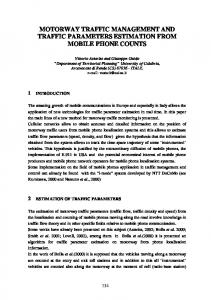
The performance evaluation of the response-sensitive traffic classes is measured in terms of throughput and packet loss. The objective of these simulations is to clearly indicate the differentiation that the flows of these classes experience under congestion, according to the proposed traffic handling mechanisms. In Figure 8, the throughput of each flow of each traffic class is presented. The differentiation between the classes is clearly observed, especially when the transmitted flows in each class is large (e.g. 1000 Kbps). In this case, the weights of the WFQ algorithm limit the rate of each flow appropriately.
in the DiffServ routers consisting the backbone network. Simulations have been performed to study the performance of traffic flowing over the Core Network. The simulation results revealed that the proposed traffic handling mechanisms achieve the primary requirements of UMTS QoS classes, which are, in a few words, delay sensitivity for Conversational and Streaming and differentiation based on priorities for Interactive and Background. Our future work will focus on the examination of alternative solutions, especially for scheduling, and the comparison among them, in order to discover the best possible solution, tailored to the needs of the UMTS QoS classes.
800
ACKNOWLEDGMENT I1 I2 I3 BG
600 400 200 0 200
400
600
800
1000
1200
Requested Rate per flow (kbps)
This work has been partially funded by the IST project FUTURE (Functional UMTS Real Emulator - IST2000-25355, URL: http://www.ebanet.it/future.htm). The opinions appearing are those of the authors and not necessarily of the other members of the Consortium. The authors wish to express their gratitude to the other members of the Consortium for valuable discussions
Figure 8. Throughput for Response-sensitive classes
Packet Loss
REFERENCES 0,035 0,03 0,025 0,02 0,015 0,01 0,005 0
I1 I2 I3 BG
200
400
600
800
1000
1200
Requested Rate per flow (kbps)
Figure 9. Packet Loss for Response-sensitive classes Similarly, in Figure 9, the packet loss for the same flows is presented. The packet loss is in the range of 10-3 when the end-to-end path is not congested, while it gradually increases to higher values in a congested situation. The desired differentiation between the Interactive and the Background flows is again clearly preserved. Finally, the responsiveness of these flows was also measured. The measured response time follows the same differentiation pattern, meaning that I1 attained the best value (35 to 200 sec), followed up by 35 to 340 sec for I2 and 38 to 600 sec for I3. Moreover, the flow submitted in Background encountered a constant aggravating response time, rising from 60 to 1600 sec. V. CONCLUSIONS This paper examined QoS provisioning in the UMTS Core Network, in case that the backbone network is based on the IP protocol and the DiffServ framework. It proposed a mapping to the IETF-specified DiffServ PHBs, and further presented a possible solution about traffic conditioning, scheduling and queue management
[1]
J. Juber, D. Weiler, H. Brand, “UMTS, the Mobile Multimedia Vision for IMT-2000: A Focus on Standardization”, IEEE Communications, September 2000, pp. 129-136. [2] G. Patel, S. Dennett, “The 3GPP and 3GPP2 Movements Toward an All-IP Mobile Network”, IEEE Personal Communications, August 2000, pp. 62-64. [3] IETF RFC 2475, S. Blake et. al., “An Architecture for Differentiated Services”, December 1998. [4] 3GPP TS 23.107, “QoS Concept and Architecture”, Release 5, January 2002. [5] 3GPP TS 23.207, “End-to-End QoS Concept and Architecture”, Release 5, January 2002 [6] G. Priggouris, S. Hadjiefthymiades, and L. Merakos, "Supporting IP QoS in the General Packet Radio Service," IEEE Network, September 2000, pp. 8-17. [7] R. Koodli and M. Puuskari, "Supporting PacketData QoS in Next-Generation Cellular Networks," IEEE Communication Magazine, February 2001, pp. 180-188. [8] H. Chaskar, R. Koodli, “MPLS and DiffServ for UMTS QoS in GPRS Core Network Architecture”, in Proceedings of INET, June 2001. [9] J. Bennett, H.Zhang, “Hierarchical packet fair queueing algorithms”, in Proceedings of SIGCOMM, 1996, pp.143-156. [10] S. Floyd, V. Jacobson, “Random early detection gateways for congestion avoidance,” IEEE/ACM Transaction on Networking, August 1993.