110
ELECTRONICS, VOL. 17, NO. 2, DECEMBER 2013
Digital Controller Development Methodology Based c on Real-Time Simulations with LabVIEW FPGA Hardware-Software Toolset Tommaso Caldognetto, Simone Buso, and Paolo Mattavelli Abstract—In this paper, we exemplify the use of NI Labc as a rapid prototyping environment for digital VIEW FPGA controllers. In our power electronics laboratory, it has been successfully employed in the development, debugging, and test of different power converter controllers for microgrid applications. The paper shows how this high level programming language, together with its target hardware platforms, including Compact RIO and Single Board RIO systems, allows researchers and students to develop even complex applications in reasonable times. The availability of efficient drivers for the considered hardware platforms frees the users from the burden of low level programming. At the same time, the high level programming approach facilitates software re-utilization, allowing the laboratory know-how to steadily grow along time. Furthermore, it allows hardware-in-the-loop real-time simulation, that proved to be effective, and safe, in debugging even complex hardware and software co-designed controllers. To illustrate the effectiveness of these hardware-software toolsets and of the methodology based upon them, two case studies are presented. Index Terms—LabVIEW FPGA, inverters, digital control, realtime simulation.
Original Research Paper DOI: 10.7251/ELS1317110C
M
I. I NTRODUCTION
OVING the first steps in digital control applications for power electronics is typically hard for many students. It requires the simultaneous use of theoretical knowledge and practical programming and experimental skills [1], [2]. Indeed, conventional integrated design environments for microcontroller, DSP, or FPGA boards are relatively complex and require considerable learning time. Besides, the peculiar nature of the control target, a switching converter processing significant amounts of electrical power, complicates the experiments, posing sometimes non negligible safety and logistic issues. At the same time, scientific research in the field of digital control applications has nowadays reached a certain maturity, so that original studies often present significant complexity, from both the theoretical and the practical implementation standpoint. As a result, the development of non trivial applications, for demonstration as well as for scientific research purposes, Manuscript received 2 October 2013. Received in revised form 18 December 2013. Accepted for publication 20 December 2013. The authors T. Caldognetto and S. Buso are with the Department of Information Engineering, University of Padova, 35131 Padova, Italy (e-mail:
[email protected],
[email protected]) The author P. Mattavelli is with the Department of Technical Management of Industrial Systems, University of Padova, 35131 Padova, Italy (e-mail:
[email protected]).
requires considerable efforts and relatively long times. All that, often, discourages students and prevents them from engaging the challenge altogether. In order to simplify the approach to this field of study, both for students and for professional researchers, our power electronics laboratory has recently begun using National Instruments reconfigurable hardware platforms (RIO devices) programmed by NI LabVIEW. In particular, FPGA based c platforms and the LabVIEW FPGA module have been acquired and used as the main hardware-software toolset for all digital control applications. The interest on digital computation platforms for the development of controllers and real-time simulation systems has increased significantly in recent years. This is also due to the needs, posed by smart grid applications, for the simulation of complex power systems [3]. In this field, popular state-ofthe-art digital platforms are: the so called Real Time Digital Simulator (RTDS) [4], from RTDS Technologies, the RTLAB [5], from OPAL-RT Technologies, and the TyphoonHIL emulators [6], [7]. RTDS and RT-LAB are PC/FPGA based special purpose computers, while the Typhoon-HIL emulators are utralow-latency platforms based on applicationspecific digital processor cores. Compared to these state-ofthe-art systems, the here identified hardware-software toolset, shows the following key features: relatively low cost, high performance, ease of use, off-the-shelf availability, affirmed and widespread use in other academic and industrial fields. In particular, with respect to other commercial integrated c design environments (IDEs), LabVIEW FPGA features an extensive set of optimized and ready to use software drivers for a large variety of hardware components, including different types of A/D converters (ADC), D/A converters (DAC), and high speed digital I/O peripherals, which greatly simplifies the implementation of data paths and, in particular, of control applications [8]. Indeed, low level programming is no longer necessary, as the environment takes care of providing an easy access to all peripherals interfaced to the target processor and/or the FPGA chip. The loss of visibility on the low level operation of the front-end circuitry is more than compensated by its high performance capability. As a result, unless one is interested in very high data transfer rates, say above 100 MSample/s, which is hardly the case for power electronic applications, the use of this tool determines no real performance limitation. The programming language is in itself extremely user friendly and, apart from being often included in the typical
ELECTRONICS, VOL. 17, NO. 2, DECEMBER 2013
student curriculum, is relatively easy to learn [8], [2]. The FPGA programming tool, in particular, is designed to appear as a particular function set, or palette, in no way different from the conventional LabVIEW programming language. Indeed, the basic data structures are the same and only a limited number of customized functions need to be studied to enable an effective FPGA chip programming. Not surprisingly, an inexperienced user is typically able to program both conventional software routines and hardware logic circuits after a limited training time. Furthermore, the developed software, thanks to its inherent orientation to modularity, is highly re-usable, which allows the laboratory to incrementally develop its own function set for the applications of interest and to maintain it for long times. Indeed, the updated programming software releases always come with a complete set of peripheral drivers, guaranteeing long term hardware/software compatibility. Finally, properly combining hardware and software resources, it is possible to set-up hardware-in-the-loop (HIL) real-time (RT) simulations of the control applications under test. This step requires the availability of, at least, two hardware platforms, one used to virtually replicate the converter electrical behavior (the plant), the other to host the control software under test. This minimal set-up allows the developer to proceed with the implementation of the controller without needing to interact with the real plant, thus avoiding all the otherwise associated potentially hazardous situations, till the very last steps of the development. In this paper, we present two examples of this novel research methodology and discuss how the use of the NI LabVIEW hardware-software toolset can effectively support the experimental research activities related to digital control in power electronics. We begin, in section II, by presenting the hardware components of the considered toolset. Then, in section III, we describe some basic building blocks of the controlling software for a voltage source inverter (VSI). The HIL RT simulation of a grid-tied VSI controlled by the introduced software modules is discussed in section IV. Lastly, in section V, we present the results of the application of this approach to the study of a relatively complex scenario, tackling the timely topic of smart microgrid control. II. H ARDWARE & S OFTWARE T OOLSET The integrated design environment (IDE) discussed in this paper is made up of both software and hardware components. c The software is represented by the LabVIEW programming suite, a widely used software for control and automation applications. In particular, control functions have been generated c with the LabVIEW FPGA module, version 12.0. A. Hardware Components The hardware components considered throughout this paper are the so called general purpose inverter controller board, or GPIC board [9], and a particular configuration of the compact reconfigurable input output embedded control system, or cRIO [10], both from National Instruments, NI. The former is the platform upon which the controllers for the target converters
111
are deployed. Its basic features are summarized in Table I. The latter, that hosts a more powerful FPGA, general purpose TABLE I C ONTROL P LATFORM C HARACTERISTICS (GPIC) Feature
Parameter
Value
Processor
Model Processor Speed
PowerPC 400 MHz
Memory
Nonvolatile System
512 MB 256 MB
Model # Slices # DSP48s
Xilinx Spartan-6 LX45 6822 58
FPGA Network
Network interface
IEEE 802.3 Ethernet
Communication
Port
RS-232, RS-485 CAN, USB
Peripherals
Channel
16 AI, 12-bit, ±10 V, 100 kHz 14 ch., 500 kHz gate drivers (1)
(1)
Only the used subset of the NI 9683 mezzanine-card ports is reported.
processor (GPP), and a freely configurable peripheral set, is used to virtualize the power converter(s) with coupling and filter networks, so as to implement HIL RT simulations. The cRIO configuration considered in this paper is presented in Table II. TABLE II S IMULATION P LATFORM C HARACTERISTICS ( C RIO-9082) Feature
Parameter
Value
Processor
Model Processor Speed
Intel Core i7-660UE 1.33 to 2.4 GHz
Memory
Nonvolatile System
32 GB (min.) 2 GB (min.)
Model # Slices # DSP48s
Spartan-6 LX150 23038 180
FPGA Network
Network interface
IEEE 802.3 Ethernet
Communication
Port
RS-232, RS-485/422, USB VGA, CAN, MXI-Express
Peripherals
Channel
4 AO, 16-bit, ±10 V, 100 kHz 8 Digital Input/Output (1)
(1)
Specs of the used digital (NI 9401) and analog (NI 9263) modules.
B. Software Components The typical inverter control software has a multi-layer structure [11]. The lowest layer is the modulation software, that generates the logic signals for the inverter switch drivers. Upon that, a current controller is implemented, whose function is to allow the voltage source inverter to operate as a controlled current source. The implementation of this layer requires a feedback loop to be closed: a current sensor is used to provide samples of the inverter phase current, acquired at strategically placed instants during the modulation period. These are later processed by a digital regulator, in the simplest case, of
112
ELECTRONICS, VOL. 17, NO. 2, DECEMBER 2013
proportional integral, or PI, type. On top of the current control layer other loops are often implemented, that depend on the particular application, like, for example, a voltage control loop, a DC-link control loop, an injected power control loop (for some grid-tied inverters). These control functions require minimum delay and tight synchronization. Therefore, they are particularly well implemented on programmable logic devices, like FPGAs, where the control delay can be minimized and jitter free synchronization between the different control layers can be achieved. As can be seen in Table I, the GPIC board is actually an heterogeneous computing platform, allowing the programmer to deploy control software both on an FPGA target and on a GPP target. A peculiar feature of the considered design environment is that the organization of the controller software, from the programmer point of view, is basically the same, irrespective of what is the target. In other words, the same data structures can be implemented, both when the controller runs on a GPP and when it is turned into the hardware configuration of an FPGA chip. It is the development environment that, almost transparently to the user, compiles the code differently, depending on the selected target. Clearly, this greatly simplifies the approach with hardware synthesized controllers. When the controller has to be deployed on an FPGA, the programmer can actually optimize the code performance and chip resource utilization, taking advantage of the specific FPGA building blocks provided within the IDE toolbox. These implement commonly used configurable fixed point arithmetic and logic functions, in some cases designed by the FPGA chip manufacturer, guaranteeing maximum data throughput. Therefore, it is wise to use them in place of the general purpose arithmetic functions, conceived to run on a GPP. The availability of a GPP on board the GPIC can be extremely useful to deal with the higher level control tasks of complex application scenarios, as it is described in the last section of this paper. III. I MPLEMENTATION E XAMPLE : I NVERTER C URRENT C ONTROLLER The first example we would like to discuss is the implementation of a digital PI current controller for a grid-tied voltage source inverter. The considered inverter model, that replicates the physical hardware available at our laboratory, is shown in Fig. 1. The inverter and controller parameters are listed in Table III. The controller building blocks are represented by: 1) PWM modulator; 2) PI current controller; 3) Current reference generator. All are meant to be deployed on the FPGA chip available on board the GPIC. In the following we discuss their implementation in more detail.
iDC S1
S2
+
VDC -
+
RPH
CDC S3
S4
LPH
iPH +
vGRID
RLOAD
CPH Ksense,i iF PWM & Drivers
PI regulator
iE -
+
iREF
Fig. 1. Inverter model for real-time simulation and control design. The inverter is grid tied and a purely resistive load is considered. TABLE III S YSTEM PARAMETERS Parameter
Symbol
Nominal input voltage Switching frequency Filter inductance Series inductor resistance Output filter capacitance Current sense gain Line inductance Load resistance Grid voltage
VDC fs LP H RP H CP H Ksense,i LGRID RLOAD vGRID
400 18 2 1 1 1 0.5 41 230
V kHz mH Ω µF V/A mH Ω Vrms
Current control bandwidth Phase margin Carrier amplitude A/D conversion delay PI calculation delay
BWI ΦM ±Ar ∆tAD ∆tcalc
1.2 60 ±27 10 1
kHz
Value
◦
µs µs
it with the modulating signal, thus generating the switch command that is sent to the DO0 pin of the control board. Even an inexperienced LabVIEW user can appreciate the simplicity of graphic programming and the easy way hardware resources are addressed within the program. This is further visible when we consider Fig. 3. Here, the acquisition of the current feedback signal is performed (note how the AI0 channel of the GPIC board is accessed) and synchronized with the modulation code through a LabVIEW peculiar structure, more commonly used in FPGA programming, known as a
A. Controller Building Blocks The software module for the PWM modulator is shown in Fig. 2. As can be seen, it is made-up of a single loop and a case structure. The latter is used to discriminate the rampup and ramp-down phases. Indeed, the modulator generates a symmetrical and centered triangular carrier, and compares
LGRID
Fig. 2. PWM modulator software module.
ELECTRONICS, VOL. 17, NO. 2, DECEMBER 2013
113
Fig. 3. Acquisition and control software module.
Fig. 4. Current reference generation software module.
frame. The current sample is then processed by a PI regulator, visible in the right hand side of the figure. The reference generation software module is represented in Fig. 4. Its basic task is to define the phase relation between the grid voltage and the injected current. In its simplest form, shown in the figure, it calculates a properly scaled replica of the grid voltage waveform (acquired at AI1 input of the GPIC board), so that only active power is injected into the grid. It is worth noting that the code here presented is not strictly optimized and represents a level 0 approach to FPGA programming in LabVIEW. It exemplifies well how, even without a deep knowledge of the underlying hardware, one can get an application running with limited effort. Besides, more sophisticated implementations are possible, where reactive power control is also guaranteed. Although we are considering a single phase converter, active/reactive power control can be implemented through the conventional d-q transformation approach, simply by creating a virtual q-axis in the synchronizing PLL algorithm. This solution is used in the application example discussed in section V. B. User Interface In a LabVIEW program, i.e. in a virtual instrument (VI), all inputs and outputs are organized and accessed via a user interface, called front panel. When the FPGA VI is launched from the IDE, the corresponding front panel is automatically reproduced on the development PC, enabling the user to set controls and view indicators. This allows the interaction with
the FPGA VI at a typical rate of several updates per second, which is adequate to the purpose of monitoring the application during debugging. A more flexible interface can be set-up through the GPP on board the RIO device which, in addition, provides a deterministic access to the FPGA application. More specifically, in this case, access to controls and indicators is programmed by the user, employing the functions of a specific interface palette, and executed by the GPP. The GPP can be further programmed to generate stimulus signals, to acquire the system response, and to present data to the user (e.g., graphically via the front panel of its LabVIEW program). The communication between the development PC and the RIO device is, in any case, provided by an Ethernet link, as shown in Fig. 5. IV. S OFTWARE D EBUGGING T HROUGH HIL RT S IMULATIONS Taking advantage of the cRIO FPGA module, it is possible to create a numerical model for the converter shown in Fig. 1, RIO Device
Development PC
Ethernet link
GPP
Communication FPGA interface User program
Internal bus
FPGA Programming Module configuration Deploying Parameter setting Visualization Datalog
GPP interface Peripheral interface User program
Peripheral connection I/O peripherals
External device (Controller, simulator or the real plant)
Fig. 5. Typical system configuration with user interface.
Scope
114
ELECTRONICS, VOL. 17, NO. 2, DECEMBER 2013
represent, in view of more complex case studies, a possible limitation of our approach. Actually, what we do can be considered as the pencil-and-paper version of the modeling approach described in [6]. Referring once more to Fig. 6, let’s point out in the following two of the challenges in obtaining precise and accurate simulation of power electronics, due to the digital nature of the simulation platforms [13]. •
•
Fig. 6. FPGA implementation of the inverter model on the cRIO hardware. Top: digital input management – middle: network topology with discrete time integrators – bottom: analog inputs and outputs management.
comprising inverter (ideally modeled as a switched voltage source controlled by a logic signal), filter/coupling network and load. The filter/coupling network and load model is analytically formulated as the zero order hold discretization (or Euler discretization) of the continuous time network equations. The discrete time versions of the electrical variable relations are subsequently turned into a LabVIEW FPGA program, taking advantage of the optimized arithmetic functions available within the toolbox. A view of the resulting program is given by Fig. 6. As we can see, an optimized digital integrator block is repeatedly used in the model definition. It is the digital counterpart of the continuous time integrator appearing in the original model. The topology of the coupling network is reflected in the way signals are routed in the block diagram of the LabVIEW program. It is worth underlining that, at this time, we do not have any automatic software tool capable of reformulating an electrical network into an FPGA compatible discrete time algorithm. The derivation of the model depicted in Fig. 6 is therefore done manually, by pencil and paper calculations, as it happens, for example, by coding with the traditional MATLAB/Simulink diagrams. Differently from ordinary coding, however, real-time simulation coding requires timing and synchronization issues to be accurately dealt with. This may
From Fig. 6, we see that the model input is represented by the PWM signal generated by the GPIC (DO0). The time resolution of the cRIO digital inputs is 100 ns, which is a relatively high value. To prevent jitter phenomena in the interpretation of the digital PWM inputs to the cRIO plant model, the time resolution of the GPIC PWM outputs should be larger than that. Indeed, in our implementation, the 7 bit carrier amplitude resolution and its 18 kHz frequency determine a 434 ns resolution, which prevents severe duty-cycle perturbations due to insufficient input resolution. The outputs of the model are the inverter phase current, the filter capacitor voltage and the grid current, AO0, AO1 and AO2 respectively. These are generated by a 16 bit DAC, whose update frequency is limited to 100 kHz. This is a rather low value, that negatively affects the quality of simulations. Indeed, the ratio of DAC update frequency over the sampling frequency is as low as 5, i.e., the analog signals are updated only five times for each sampling period. In the case of the inverter phase current, this causes significant sampling noise and triggers spurious controller dynamics. The ideal solution would be to use higher throughput DACs; for the time being, the current controller bandwidth is kept lower than the typical tenth of switching frequency, so as to increase the controller robustness to injected noise. It is worth noting that this hardware limitation has an impact on the model discretization step as well. The model is obviously solved by fixed step integration, therefore, frequency response warping can take place close to the Nyquist limit. This is the reason why, in principle, the discretization step should be kept as low as possible. Unfortunately, discretization steps lower than 10µs make little sense with the available DACs.
Despite the outlined issues, a typical outcome of the system’s simulation is shown in Fig. 7. As can be seen, the obtained waveforms are acceptably smooth. The simulation represents the case when the inverter is controlled to deliver exactly the active power drawn by the resistive load. As a result, the current on the grid is practically zero. As a matter of fact, a small amount of reactive power is absorbed by the inverter output filter, which is provided by the grid, determining the small line current visible in the figure. The result proves that the model is capable of replicating the expected system behavior. By routine, HIL simulations are always cross checked with conventional simulations, e.g., c based on MATLAB/Simulink models, at least for short simulation times like those here considered. The results are not shown here because they appear identical to those of
ELECTRONICS, VOL. 17, NO. 2, DECEMBER 2013
115
Cooperative controller
Supervision & datalog cRIO Real-Time FPGA
Development PC cRIO
- Development platform - Graphical Interface
Real-Time
- Data Storage
FPGA
- General Purpose Computing
Snom , GPIC Sref
SLOAD , SPCC
Real-Time
Ethernet network
FPGA
Analog channels GRID
Simulated topology EPP #1
(controlled quantities)
Digital channels
EPP #2
2
2
1
1
E
1
2
-
2
+ -
1
2
LOAD
1
1
-
2
+ -
+
1
1
E
2
2
(gate signals) +
Control emulation
Plant RT simulation Fig. 8. Considered model for cooperative control test: real-time simulation system.
Inverter current
KSENSE,i = 1 A/V
Microgrid switchgear
Grid emulator SICON
Cables
cRIO-9082
vPCC Sref,1 Snom,1
(64 kW / 80 kVA, 230 Vrms)
(3 kW / 3.5 kVA)
GPIC
Load current
SELCO inv.
Line current
EPP #1
(3 kW // 1kVAR)
GPIC
CL
SPCC SLOAD BG (260 m)
B1 (120 m)
cRIO Cooperative controller Sref,1, Sref,2
Snom,1, Snom,2
Load
Fig. 7. After that, the controller running on the GPIC can be considered functional and the developed software/hardware control system can be embedded into the physical inverter. As a final remark, it is interesting to note that the FPGA resource utilizations for the simple codes presented so far are 12% on the GPIC and 11% on the cRIO, without any specific code optimization. V. A M ORE C OMPLEX S CENARIO : C OOPERATIVE C ONTROL L OW-VOLTAGE M ICROGRID The limited hardware considered in this paper is actually capable of sustaining more complex control application scenarios. To give a further example, we now propose a situation where two current mode controlled inverters operate in a
RL Sref,2 Snom,2
(3 kW / 3.5 kVA)
GPIC
SELCO inv.
Fig. 7. HIL RT simulation of inverter current control – depicted waveforms: inverter current (yellow), line current (light blue), resistive load current (green) – horizontal: 4 ms/div; vertical: 1 A/div.
EPP #2
Ethernet network
B2 (200 m) Dev. PC Supervision & datalog PC
GPIC
Fig. 9. Considered model for cooperative control test: experimental set-up.
centrally supervised microgrid. The purpose of the supervising strategy, which is described in detail in [15], is to coordinate the two inverters so as to minimize conduction losses on the grid. The basic idea is that the inverter that is placed closer to the load, which is known to the central supervisor, should supply the larger part of the needed active and reactive power. A schematic representation of this case study is shown by Fig. 8, presenting a view of the hardware organization for the
116
ELECTRONICS, VOL. 17, NO. 2, DECEMBER 2013
Load voltage (50 V/div) Load current (1 A/div) EPP1 current (1 A/div) EPP2 current (1 A/div)
20 15 10 5 0 −5 −10 −15 −20 0
0.01
0.02
0.03 0.04 Time (s)
0.05
0.06
0.07
Fig. 10. HIL RT simulation test of the cooperative control strategy for a microgrid.
Load voltage (50 V/div) Load current (1 A/div) EPP1 current (1 A/div) EPP2 current (1 A/div)
20 15 10 5 0 −5 −10 −15 −20 0
0.01
0.02
0.03 0.04 Time (s)
0.05
0.06
0.07
Fig. 11. Experimental test of the cooperative control strategy for a microgrid.
HIL RT simulation, and Fig. 9, illustrating the corresponding experimental set-up. The addressed system is actually a simple kind of grid-connected microgrid. It is composed of two inverters, also named electronic power processors (EPPs), connected by the distribution branches B1 and B2 to a linear load. The connection to the main grid is provided by the branch BG , visible in Fig. 9. The set-up can be considered as a test bench for inverter control techniques and, as is discussed in the following, for optimum management algorithms for smart microgrids [14]. As can be seen, in this case the scenario is much more complex: not only two inverters are considered, but a new digital device comes into play, that is the centralized grid supervisor. Its task is to acquire the total load power absorption, to compute active and reactive power set-points for each inverter, and to periodically transmit them through the communication channel. Therefore, in addition to the local control for each inverter, here the study elaborates also on supervising control and communication channels. The software development and debugging follows exactly the same line described above for the simple case of the basic current controller, comprising coding, HIL RT simulations and experimental tests. As far as code is concerned, the main distinctive features for the local inverter controllers (GPIC) required by this study are: 1) the activation of a communication channel (Ethernet)
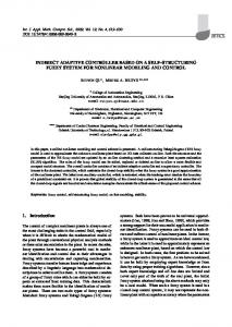
linking the GPIC devices to the central supervisor; 2) the use of d-q transformation to convert active and reactive power set-points into a suitable reference current signal which, in turn, requires 3) the implementation of a digital PLL that synchronizes each inverter to its local grid voltage. It is worth noting that the communication channel is managed by the GPP on the GPIC device, so that it does not impact on the FPGA utilization, which is now higher, approximately equal to 50% of the total capability, due to the implementation of functionalities 2) and 3), but still far from saturation. The centralized supervisor is implemented on a cRIO device, exploiting its on board real-time GPP to run the cooperative control algorithm. Being the computational burden not so light, the GPP has been used to take advantage of single precision floating point arithmetic. As mentioned above, the details concerning the supervising strategy, i.e., the logic based on which the supervisor determines the optimal power set-points for the microgrid inverters, are described in detail in [15]. Very basically, the optimization objective is to keep the grid losses to a minimum. From the inverter controller standpoint, this simply means that externally computed active and reactive power set-points are periodically received through the communication channel. As a final remark on the cooperative control implementation, Ethernet networking has been used to implement the communication links as it is natively embedded in the controller hardware and supported by software. We would like to emphasize that this does not impair the capability of the illustrated set-up to validate any control strategy, nor reduce its flexibility to integrate other communication technologies, like, for example, power line communication (PLC). We observe that the integrated multi-layer architecture of the controlling hardware, that hosts not only programmable logic circuitry, but a fully functional GPP as well, and seamlessly manages data exchange between the two computational layers, is what really enables a rapid development of this experiment. Thanks to that, for example, it is relatively easy to implement the required Ethernet communication links. Besides, all the system can be remotely monitored, as each device can be accessed from a conventional PC to perform, e.g., data logging and off-line processing. As far as HIL simulations are concerned, we use, once again, a cRIO unit, whose FPGA runs the controlled plant model. This comprises the two inverters, a passive parallel connected R-C load and the interconnecting power network. The resulting FPGA occupation is nearly 50%. From this standpoint, minor improvements can be obtained optimizing the FPGA code of the model, but it is clear that, with our hardware, the set-up shown in Fig. 8 and Fig. 9 defines the manageable complexity level of the systems that can be simulated. To go further, we have recently acquired a much more powerful hardware platform, known as PXI, [12], whose FPGA boards offer about a tenfold increase in capacity and whose analog and digital peripherals allow multi-MHz update frequencies, solving all previously mentioned issues. Fig. 10 and Fig. 11 show how the system operates in HIL RT simulations and in real life, respectively. The simulation
ELECTRONICS, VOL. 17, NO. 2, DECEMBER 2013
used to develop software applications for GPPs, thus allowing effective hardware/software co-design. To exemplify its usage, a digital current controller for a 3 kVA grid-tied inverter is considered, whose basic building blocks are illustrated. Exploiting two different hardware platforms, hardware-in-the-loop realtime simulations are possible and represent an effective means for safe and accurate controller debugging and tuning. The current controller can be embedded into more sophisticated inverter applications. As a final example, the centralized cooperative control of two current mode controlled inverters, connected to a microgrid, is presented. This example allows to verify how, applying the proposed methodology, different issues, typical of smart grid control, can be addressed, both in HIL RT simulations and in experiments. These include local inverter control, centralized or distributed grid optimization, communication channels.
TABLE IV C OOPERATIVE CONTROL TEST PARAMETERS Parameter
Symbol
Value
BG branch resistance B1 branch resistance B2 branch resistance Load capacitance Load resistance Grid voltage
RBG RB1 RB2 CLOAD RLOAD vP CC
0.6 0.4 0.7 60 47/3 230
Ω Ω Ω µF Ω Vrms
Current control bandwidth Phase margin Reference update period
BWI ΦM ∆tupdate
2 60 5
kHz ◦
s
Losses − RC load: 15.7 Ω // 60 µF P2,ref /10 (W)
Losses (W) P1,ref /10 (W)
400
PLtot /10 (W)
300
R EFERENCES
Load connection
200
Load disconnection
150 W cooperative control regime
100
75 W
0 0
10
20
30
40
50
Time /s (a)
117
(b)
(c)
(d)
(e)
(f)
(g)
(h)
(i)
Fig. 12. Measured power losses for the experimental test.
parameters are summarized in Table IV; basically, the simulation and experiment start with disconnected inverters and the utility grid feeding the loads. The microgrid supervisor computes the optimal references and dispatches them at time t = 0. As a result, both inverters begin injecting the calculated active and reactive power as soon as the new power references are received, as is visible from the phase relation between load voltage, the yellow trace, and inverter currents, the purple and green traces. It is possible to see how the simulation correctly predicts the experimental results. Lastly, Fig. 12 shows the power response of the experimental set-up while it undergoes a load connection and disconnection. It is noticeable the effect of the cooperative control of the power injected by the two inverters on distribution losses. In particular, due to the proposed algorithm, distribution loss decreases by 50% once the cooperative control regime establishes. Corresponding results were achieved from the HIL RT simulation of the experimental set-up. VI. C ONCLUSION c The application of LabVIEW FPGA as a design environment allowing the rapid prototyping and the HIL RT simulation of digital controllers for power converters is discussed in this paper. Thanks to its user friendliness, the tool allows even inexperienced users to start programming FPGA chips after a relatively brief training phase. At the same time, it can be
[1] Sanghun Choi; Saeedifard, M., “An Educational Laboratory for Digital Control and Rapid Prototyping of Power Electronic Circuits,” Education, IEEE Transactions on, vol.55, no.2, pp.263,270, May 2012. [2] Jimenez-Martinez, J.M.; Soto, F.; De Jodar, E.; Villarejo, J.A.; RocaDorda, J., “A New Approach for Teaching Power Electronics Converter Experiments,” Education, IEEE Transactions on, vol.48, no.3, pp.513,519, Aug. 2005. [3] Dufour, C.; Blanger, J., “On the Use of Real-Time Simulation Technology in Smart Grid Research and Development”, ECCE 2013, Denver, USA. [4] Jin-Hong Jeon; Jong-Yul Kim; Hak-Man Kim; Seul-Ki Kim; Changhee Cho; Jang-Mok Kim; Jong-Bo Ahn; Keo-Yamg Nam, “Development of Hardware In-the-Loop Simulation System for Testing Operation and Control Functions of Microgrid,” Power Electronics, IEEE Transactions on, vol.25, no.12, pp.2919,2929, Dec. 2010. [5] Abourida, S.; Belanger, J., “Real-Time Platform for the Control Prototyping and Simulation of Power Electronics and Motor Drivers”, Proceedings of the Third International Conference on Modeling, Simulation and Applied Optimization Sharjah,U.A.E, January 20-22 2009. ˇ ˇ [6] Veki´c, M.S.; Grabi´c, S.U.; Majstorovi´c, D.P.; Celanovi´ c, I.L.; Celanovi´ c, N.L.; Kati´c, V.A., “Ultralow Latency HIL Platform for Rapid Development of Complex Power Electronics Systems,” Power Electronics, IEEE Transactions on, vol.27, no.11, pp.4436,4444, Nov. 2012. ˇ [7] Adˇzi´c, E.M.; Adˇzi´c, M.S.; Kati´c, V.A.; Marˇceti´c, D.P.; Celanovi´ c, N.L., “Development of High-Reliability EV and HEV IM Propulsion Drive With Ultra-Low Latency HIL Environment,” Industrial Informatics, IEEE Transactions on, vol.9, no.2, pp.630,639, May 2013. [8] Balid, W.; Abdulwahed, M., “A novel FPGA educational paradigm using the next generation programming languages case of an embedded FPGA system course,” Global Engineering Education Conference (EDUCON), 2013 IEEE, vol., no., pp.23,31, 13-15 March 2013. [9] National Instruments Single Board RIO - General Purpose Inverter Controller; http://www.ni.com/singleboard/gpic/ [10] NI CompactRIO - reconfigurable controller; www.ni.com/compactrio/ [11] Rocabert, J.; Luna, A.; Blaabjerg, F.; Rodr´ıguez, P.,“Control of Power Converters in AC Microgrids,” Power Electronics, IEEE Transactions on, vol.27, no.11, pp.4734,4749, Nov. 2012. [12] NI PXI Platform - PC based platform for test, measurement and control; http://www.ni.com/pxi/ [13] Graf, C.; Maas, J.; Schulte, T.; Weise-Emden, J., “Real-time HILsimulation of power electronics,” Industrial Electronics, 2008. IECON 2008. 34th Annual Conference of IEEE, vol., no., pp.2829,2834, 10-13 Nov. 2008. [14] Tenti, P.; Costabeber, A.; Caldognetto, T.; Mattavelli, P., “Cooperative control of smart micro-grids based on conservative power commands”, 11th conference- seminar international school on nonsinusoidal currents and compensation, ISNCC, ID: T-4, June 2013. [15] Costabeber, A.; Caldognetto, T.; Tenti, P.; Mattavelli, P., ’Improving Microgrid Performance by Cooperative Control of Distributed Energy Sources’, ECCE 2013, Denver, USA.