cant increase in the amount of simulation required to design digital systems.
Simulation time typically scales as the square of the increase in system
complexity ...
Digital System Simulation: Methodologies and Examples Kunle Olukotun, Mark Heinrich and David Ofelt Computer Systems Laboratory Stanford University Stanford, CA 94305-4070
1
Introduction
Two major trends in the digital design industry are the increase in system complexity and the increasing importance of short design times. The rise in design complexity is motivated by consumer demand for higher performance products as well as increases in integration density which allow more functionality to be placed on a single chip. A consequence of this rise in complexity is a significant increase in the amount of simulation required to design digital systems. Simulation time typically scales as the square of the increase in system complexity [4]. Short design times are important because once a design has been conceived there is a limited time window in which to bring the system to market while its performance is competitive. Simulation serves many purposes during the design cycle of a digital system. In the early stages of design, high-level simulation is used for performance prediction and analysis. In the middle of the design cycle, simulation is used to develop the software algorithms and refine the hardware. In the later stages of design, simulation is used make sure performance targets are reached and to verify the correctness of the hardware and software. The different simulation objectives require varying levels of modeling detail. To keep design time to a minimum, it is critical to structure the simulation environment to make it possible to trade-off simulation performance for model detail in a flexible manner that allows concurrent hardware and software development. In this paper we describe the different simulation methodologies for developing complex digital systems, and give examples of one such simulation environment. The rest of this paper is organized as follows. In Section 2 we describe and classify the various simulation methodologies that are used in digital system design and describe how they are used in the various stages of the design cycle. In Section 3 we provide examples of the methodologies. We describe a sophisticated simulation environment used to develop a large ASIC for the Stanford FLASH multiprocessor.
2 2.1
Simulation Methodologies Design Level
During the design cycle of an ASIC or processor that is a part of a complex digital system a variety of simulators are developed. These
simulators model the design at different levels of abstraction and typically become slower as the design progresses to lower levels of abstraction. Description language
Primitives
Algorithm
HLL
Instructions
10–100
Architecture
HLL
Functional blocks
1K–10K
HLL, HDL
RTL primitives
1M–10M
HDL, Netlist
Logic gates
10M–100M
Design level
Register transfer Logic
Simulation slowdown
Table 1. Digital system design levels. The simulation slowdown assumes the processor is simulating a model of itself. Table 1 shows the design levels typically used in the process of creating a digital system [9]. The highest level of system design is the specification of the algorithm or protocol that the system will perform. Many digital systems are programmable to make them flexible and to make the system easier to debug. The programmable element might be a general purpose processor or an applicationspecific instruction-set processor (ASIP) [5]. If the system contains an ASIP, the design of the instruction set will have a large impact on the performance and flexibility of the system. Instruction set design is typically performed with the aid of an instruction level simulator. Simulating the system at the instruction level can be done with instruction interpretation [19] or binary translation [3]. Due to the similarity between instructions of an ASIP and the instructions of general purpose processors, instruction level simulation only requires tens or hundreds of instructions for each simulated instruction. This results in high simulation performance of 1 million to 10 million instructions per second on a 100 MIPS workstation. At the architecture level designers are concerned with defining and estimating the performance of the main functional blocks in the system. An example of this is the design of the interconnection network and communication protocols used to interconnect processors in a heterogeneous multiprocessor system. Another example is the design of a processor’s execution pipeline together with its memory hierarchy and I/O system [11]. At the architectural level, designers are interested in estimating overall system performance and collecting performance data to guide architectural design trade-offs. The speed of simulation at this level depends on the level of detail that is modeled, but usually results in simulation speeds that vary between 10 and 100 kHz on a 100 MIPS workstation. At the register transfer level the goal is to model all the components in the system in enough detail so that performance and correctness can be modeled to the nearest clock cycle. At this level of simulation the simulator accurately models all the concurrency and
resource contention in the system. The level of detail required to do this for the complexity of current chips makes RTL simulation slow even for the fastest simulators [22]. Despite their slow speed, RTL simulators are heavily used to check the correctness of the system. The performance of RTL simulation varies between 10 and 100 Hz on a 100 MIPS workstation. The high demand for simulation cycles for both performance and correctness verification makes simulation speed at this level a critical factor in determining the quality of the system design. At the logic level all the nets and gates in the system are defined. At this point the design could be used to drive the surrounding system. However, the number of primitives and the characteristics of gate level models constrain their simulation performance to between 1 and 10 Hz on a 100 MIPS workstation. This performance is typically too low to allow the simulation of significant system applications at the logic level.
2.2
Simulation Input
An important consideration in developing a simulation model is the manner in which simulation input is provided to the model. There are three basic techniques: statistics-driven simulation, trace-driven simulation and execution-driven simulation. These techniques differ in the completeness of the simulation model. In statistics-driven simulation the input is a set of statistics gathered from an existing machine or a more complete simulator. These statistics are combined with static analysis of the behavior of the instruction set or architecture to provide early performance estimates. For example, instruction-mix data can be combined with predicted instruction execution latencies to estimate the performance of a pipelined processor [11]. Statistics-driven simulation models are very simple because they leave much of the system unspecified. In trace-driven simulation the input data is a sequence of events that is unaffected by the behavior of the model. Trace-driven simulation is used extensively in instruction set design where the input events are a sequence of instructions. However, it is possible to develop a trace-driven processor model at any of the design levels discussed above. Trace-driven memory-system simulators are also quite common. Here the trace is a sequence of memory address references. Trace-driven simulation is also used in the design of network routers and packet switches. Although trace-driven simulators are simpler and faster than execution-driven simulators because they do not model data transformations, trace-driven simulators must be fed from a trace that comes from an execution driven-simulator or an existing digital system that has been instrumented for trace collection [18]. Trace-driven simulation is primarily used for detailed architecture performance prediction. In execution-driven simulation the exact sequence of input events is determined by the behavior of the simulation model as it executes. Execution-driven simulators are developed later in the design cycle because they tend to have more design detail. They require more design detail to model the data transformations that must occur to accurately simulate the behavior of the system. Execution-driven simulation is essential during the later stages of the design cycle when the design is being verified for correctness. For example, while it is possible to accurately estimate the performance of a branch prediction algorithm using trace-driven simulation, execu-
tion-driven simulation is required to verify that the branch missprediction recovery mechanisms work correctly.
2.3
Simulating Concurrency
Concurrency is a component of all digital systems. In fact, built-in support for concurrency is the main characteristic that distinguishes hardware description languages like Verilog and VHDL from highlevel languages like C. The way concurrency is simulated has a large impact on both simulation performance and modeling flexibility. The classic way of simulating concurrency is to make use of a dynamic scheduler which orders the execution of user defined threads based on events. This is known as discrete-event simulation and is the most flexible method of simulating concurrency. This is the model of concurrency that is embodied in Verilog and VHDL semantics, but it can be added with library support to C. The drawback to discrete-event simulation is low simulation performance due to the runtime overhead of dynamic event-scheduling. A number of techniques have been used to improve the performance of discrete-event simulation by reducing the event scheduler overhead [14, 20]. These techniques sacrifice some of the generality of eventdriven simulation to achieve higher performance. The alternative to dynamic event-scheduling is cycle-based simulation. In cycle-based simulation all components are evaluated once each clock cycle in a statically-scheduled order that ensures all input events to a component have their final value by the time the component is executed. Cycle based logic simulators which are also called levelized compiled code logic simulators rely on the synchronous nature of digital logic to eliminate all considerations of time that are smaller than a clock cycle. Cycle based simulators have the potential to provide much higher simulation performance than discrete-event simulators because they eliminate much of the run time processing overhead associated with ordering and propagating events [1, 6, 22]. Some cycle-based logic simulators dispense with the accurate representation of the logic between the state elements altogether and transform this logic to speed up simulation even further [15]. The main disadvantage of cycle-based simulation techniques is that they are not general. These techniques will not work on asynchronous models. In practice, even though most digital systems are mostly synchronous, asynchronous chip interfaces are common.
2.4
Managing Simulation
Complex digital systems design requires a sophisticated simulation environment for performance prediction and correctness validation. Most systems are composed of hardware and software and it is desirable to develop the hardware and the software concurrently. In the later stages of the design once the components of the system have been described at the RTL level, it is often necessary to simulate the whole system with realistic input data; however, the slow simulation speed of RTL-level models makes this computationaly expensive and time consuming. Two simulation management techniques that have proved to be useful in providing solutions to these problems are the use of multi-level simulation in which models at different design levels are simulated together [2] and dynamic switching between levels of detail [17]. Multi-level simulation can be used to support concurrent software and hardware development of an ASIP with specialized functional
units in the following way. Software development can use a fast instruction level simulator of the ASIP while hardware development of the functional units takes place at the RTL level. Multi-level simulation incorporates both types of simulator so that the RTL-level models can seamlessly replace the high-level descriptions of the specialized instructions. Dynamic switching between levels of detail takes multi-level simulation one step further. It allows the models of the specialized functional units to be dynamically switched at simulation time. This ability makes it possible to run realistic workloads on a detailed model while keeping simulation time reasonable. Simulation typically begins using the high-level fast simulator, and then when an interesting region of the simulation is reached, the high-level model is switched to the detailed model. The detailed model can be switched back to the less detailed model to quickly simulate unimportant portions of the workload. This switching back and forth can take place repeatedly and may involve multiple model levels with different speed-detail characteristics. This technique is very effective at simulating realistic workloads in their entirety because, as Table 1 shows, the simulation speed difference between the algorithmic level and the logic levels can span five orders of magnitude.
3
FLASH Case Study
This section gives a brief description of the FLASH multiprocessor, concentrating on the design and verification of MAGIC, the large ASIP node controller for the FLASH machine. The simulation methodology used in the FLASH design is discussed in detail as a real-life example of the environment required to develop a complex digital system.
3.1
FLASH Overview
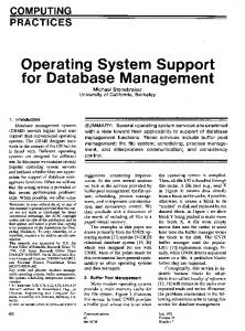
The Stanford FLASH multiprocessor [12] is a general-purpose multiprocessor designed to scale up to 4096 nodes. It supports applications which communicate implicitly via a shared address space (shared memory applications), as well as applications that communicate explicitly via the exchange of messages (message passing applications). Hardware support for both types of communication is implemented in the MAGIC chip, the communication controller of the FLASH node. MAGIC contains an embedded, programmable protocol processor that runs software code sequences to implement communication protocols. Since these protocols can be quite complex, this approach greatly simplifies the hardware design process, and reduces the risk of fabricating a chip that does not work. A programmable protocol processor also allows great flexibility in the types of communication protocols the machine can run, and permits debugging and tuning protocols or developing completely new protocols even after the machine is built. The structure of a FLASH node, and the central location of the MAGIC chip is shown in Figure 1. The MAGIC chip integrates interfaces to the main processor, memory system, I/O system, and network with the programmable protocol processor. As the heart of a FLASH node, MAGIC must concurrently process requests from each of its external interfaces and perform its principal function— that of a data transfer crossbar. However, MAGIC also needs to perform bookkeeping to implement the communication protocol. It is the protocol processor which handles these control decisions, and properly directs data from one interface to another.
2nd-Level 2$ 2nd-Level Cache Cache
DRAM DRAM
MIPS µP R10000
Net
I/O MAGIC MAGIC
Figure 1. The Stanford FLASH multiprocessor. MAGIC must control data movement in a protocol-dependent fashion without adversely affecting performance. To achieve this goal, the chip separates the data-transfer logic from the control logic. The data transfer logic is implemented in hardware to achieve lowlatency, high-bandwidth data transfers. When data enters the MAGIC chip it is placed in a dedicated on-chip data buffer and remains there until it leaves the chip, avoiding unnecessary data copying. To manage their complexity, the shared memory and messaging protocols are implemented in software (called handlers) that runs on the embedded protocol processor. The protocol processor is a simple two-way issue 64-bit RISC processor with no hardware interlocks, no floating point capability, no TLB or virtual memory management, and no interrupts or restartable exceptions. The MAGIC chip was fabricated as a standard-cell ASIC with the cooperation of LSI Logic. The die is 256mm2 and contains approximately 250,000 gates and 220,000 bits of memory, making it large by ASIC standards. One of our 18 on-chip memories is a custom, 6port memory that implements 16 128-byte data buffers, the key to our hardware data-transfer mechanism. The combination of multiple interfaces, aggressive pipelining, and the necessity of handling multiple outstanding requests from the main processor makes MAGIC inherently multithreaded, posing complex verification and performance challenges. DASH Counts/Hand-calculated latencies
Dirsim/Dinero
FlashLite w/ C-Handlers
FlashLite w/ PPSim
Verilog Model Gate-level Model
FlashLite/Verilog FlashLite/Verilog/R10000
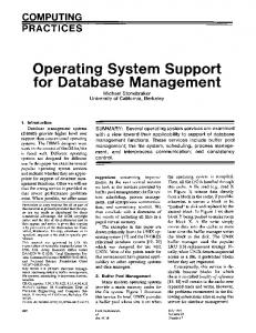
Figure 2. Simulation hierarchy used in the FLASH design.
As shown in Figure 2, the simulation strategy for FLASH went through several phases, moving from low-detail exploratory studies early in the design to very detailed gate-level simulations. The following sections describe each of these phases in more detail.
3.2
Initial Design Exploration
Early on in the FLASH design, we decided to use an ASIP to implement the communication controller and to use a data cache to reduce the amount of SRAM needed for protocol storage. The first studies we performed were to decide if the ASIP would be efficient enough to implement protocols in software at “hardware-like” speeds, and if a cache for protocol data could achieve high hit-rates.
FlashLite, a simulator for the entire FLASH machine. FlashLite uses an execution-driven processor model [8, 17] to run real applications on a simulated FLASH machine. FlashLite is written in a combination of C and C++ and uses a fine-grained threads package [16] that allows easy modeling of the functional units and independent state machines that comprise MAGIC.
Cache
3.2.1 ASIP Performance The first design problem was to determine if an ASIP would be fast enough to act as a protocol engine for the FLASH machine. At this point, the architecture of the machine was very vague and we had no simulation environment, but we needed to generate performance numbers to guide the design decisions. We used a previous research prototype built in our group, the Stanford DASH machine [13], to generate event counts from the SPLASH parallel application suite [21]. We wrote the important protocol handlers by hand in MIPS assembly to get an estimate for how long each of the protocol operations would take. Overall machine performance was obtained by multiplying the event counts by the handler estimates and summing over all handlers. This approach gave us a good idea on what the average performance of the machine would be, and demonstrated that a generalpurpose CPU core could come within a factor of two of the performance needed for MAGIC. Once we had these base performance estimates, we changed the handler cycle counts to account for our estimates of various hardware features that would help accelerate protocol handling, to see how the performance would change. Unfortunately, since the input data is based on statistical averages, it is not possible to generate information about contention. In machines like FLASH, contention is a major performance issue, so it is important to model contention accurately in the simulation environment.
3.2.2 Cache Performance The other major design issue we needed to confirm was the idea of caching the protocol data in the protocol processor's data cache. To study this we wrote a very simple discrete event model that implemented the general cache coherence protocol. This model was again driven by programs from the SPLASH application suite. The output from the model was a trace of addresses generated by the loads and stores executed by the protocol processor. We fed this address trace into the Dinero [7] cache simulator to study cache miss rates over a wide range of standard cache parameters. Since we were interested in obtaining average cache statistics rather than absolute performance from this model trace-driven simulation was an acceptable choice. The results of this study demonstrated that a protocol data cache would work well.
3.3
FlashLite
Our initial simulation studies confirmed that implementing the communication controller as an ASIP was a good idea. We now needed to understand the relationship of MAGIC’s performance to overall system performance. To discover this, we constructed
Processor
DRAM In
N e t w o r k
Out
MC PI
In
Out
NI
Inbox
IO
I n O u t
Protocol Processor
I n O u t
IO
Outbox MAGIC ICache
MAGIC
C-handlers
or
MAGIC DCache
PPsim
Figure 3. The different FlashLite threads that model the entire FLASH system. Figure 3 shows the major FlashLite threads that make up a single FLASH node. The protocol processor thread can itself be modeled at two levels of detail. The next two sections describe why this is an important feature.
3.3.1 FlashLite - “C-handlers” Initially the FlashLite threads comprising the communication controller were an abstract model of the MAGIC chip, parameterized to have the same basic interfaces. At that point, we were able to vary high-level parameters to determine what we could do well in the software running on the protocol processor, and what needed to be done with support from the surrounding hardware. As the MAGIC architecture evolved, so did FlashLite, until eventually FlashLite had accurate models of all the on-chip hardware interfaces except for the protocol processor itself. This was natural, since the instruction set architecture of the protocol processor was not yet defined. However, FlashLite was still able to simulate the entire MAGIC chip by having a high-level model of the protocol processor that ran the communication protocol in C (the “C-handlers” and provided approximate delays to the basic protocol actions like sending messages and manipulating protocol state. The C-handlers played a crucial role in FLASH development, as they allowed the protocols to be written and debugged, and high-level design decisions to be made while the MAGIC hardware and the protocol processor instruction set were still being designed.
3.3.2 FlashLite - PPSim The next major step in the project was the design of the instruction set architecture of the protocol processor. Once we had the basic instruction set designed (we built our instruction set on top of MIPS ISA) one of the first simulation tools we created to look at the tradeoffs in instruction-set design was an instruction level simulator for the protocol processor. Along with this simulator, we developed a series of other software tools, including a C-compiler, scheduler, and assembler for translating the handlers into object code executable by the real machine. The simulator, PPsim, became FlashLite’s detailed thread for the protocol processor as shown in Figure 3.
3.3.3 Speed-Detail Trade-offs FlashLite retained the ability to run C-handlers, but it could now also use PPsim run the compiled protocol code sequences as they would execute on the real machine, complete with cache models for the MAGIC instruction and data caches. For speed and debugging flexibility, FlashLite had the ability to switch between C-handlers and PPSim on a fine-grain level (handler by handler). While PPsim ran slower than C-handlers (see Table 2), it provided a model with accurate timing, and provided new information such as actual instruction counts, cycle counts, and accurate MAGIC cache behavior. Integrating PPsim into FlashLite also had the advantage of allowing us to debug the compiler, scheduler, and assembler before we ever ran any code on the RTL description of the MAGIC chip.
3.4
Verilog
Once the architecture started to solidify, work on the RTL design began in earnest. This work was done completely in parallel with the work on software tools and the fine-tuning of MAGIC’s parameters with FlashLite and PPsim.
3.4.1 Verilog - RTL The MAGIC chip design is implemented in well over 110,000 lines of Verilog. Most of the verification effort focused on this level of detail. We generated a large set of directed and random diagnostics that were run on the Verilog model. To make sure that no illegal conditions arose, the design was liberally annotated with sanity checking code that would not be part of the physical chip, but helped to indicate when a problem arose during verification.
3.4.2 Verilog - Gate-level Using logic synthesis and libraries supplied by LSI Logic, we converted the RTL MAGIC description into a gate-level netlist description of the chip. This is the lowest-level description of MAGIC in our design methodology, so all diagnostics had to pass on this version before we sent MAGIC out for fabrication. As Table 2 shows though, the gate-level simulation is by far the slowest since it is the most detailed. For this reason, most diagnostic development and verification effort was spent at the behavioral RTL-level, and only when we had developed a large suite of random and direct diagnostics did we simulate at this lowest level to make sure the chip was really ready for fabrication.
Simulation Level
Speed (Hz)
FlashLite—C handlers
90,000
FlashLite—PPsim
80,000
Verilog—RTL
13
Verilog—Gate-Level
3
Table 2. Simulation Speed at Different Levels in the Hierarchy.
3.5
Putting it All Together
To test the RTL-level MAGIC design with realistic workloads we combined some of our simulation models in interesting ways. Two of the issues that lead us to do multi-level simulations for the hardware design were the correctness of the chip when running a realistic workload and the correctness of the chip interfaces when communicating with the other chips on the board.
3.5.1
FlashLite-Verilog
Ultimately we are interested in the overall performance of FLASH as a multiprocessor. To get this information we needed to see how a realistic workload would run on the hardware. We were particularly interested in how efficiently the protocol processor supported the multiprocessor cache coherency protocols. Unfortunately, the performance of the RTL model is so poor, that it would be impractical to replicate the model N times to build a Nprocessor simulation. Instead, we used the FlashLite simulator to model N-1 of the nodes, and replaced a single node with the Verilog model of the MAGIC chip. Since FlashLite is much faster than the Verilog, the resulting simulation ran only slightly slower than the Verilog model by itself and allowed us to verify MAGIC with a realistic workload.
3.5.2 FlashLite-Verilog-R10000 The other major issue that lead us to use multi-level simulation was the task of confirming that MAGIC could communicate with the other chips on the node board. One of these chips was the compute processor for FLASH, the MIPS R10000. In our simulation infrastructure, we replaced the high-level model of the processor we used in Section 3.5.1 with the real RTL model of the MIPS R10000. By running the realistic workloads within this simulation environment we had high confidence that the processor interface of MAGIC would work.
3.6
FLASH Conclusions
The evolution of the FLASH and MAGIC designs show that the simulation environment is intimately linked with the design task at hand. In the early stages of design low-detail statistics-driven simulation was used to quickly verify high-level architectural design decisions. Once the basic architecture was defined—an ASIP control path surrounded by dedicated data-movement hardware—more detailed execution-driven simulation was used to provide guidance for detailed architectural trade-offs. The result of these architectural trade-offs was an RTL model that could be used to drive ASIC design tools.
Two themes that emerge from the FLASH design are the need for simulation to support concurrent software and hardware development and the need to drive simulations with realistic workloads. The simulation environment was structured to allow the software development to commence using PPsim while the RTL development proceeded in parallel. Once the RTL-level design was complete, accurate performance evaluation was possible by using realistic workloads. Multi-level simulation is the key methodology that made this feasible.
[15] P. McGeer et al. “Fast discrete functional evaluation using decision diagrams,” Proceedings of IEEE/ACM International Conf. Computer-Aided Design, pp. 402– 407, San Jose, CA, November 1995. [16] D.P. Reed and R K. Kanodia, “Synchronization with Eventcounts and Sequencers, “Communication of the ACM, vol. 22, no. 2, February 1979 [17] M. Rosenblum, S. Herrod, E. Witchel, and A. Gupta, “The SimOS approach,” IEEE Parallel and Distributed Technology, vol. 4, pp. 34–43, 1995.
Acknowledgments
[18] M. D. Smith, “Tracing with Pixie,” Stanford University, Computer Systems Laboratory, Technical CSL-TR-91497, November 1991.
This work is supported by DARPA contract number DABT63-94C-0054. The authors also thank the entire FLASH development team.
[19] J. Veenstra, “MINT a front end for efficient simulation of shared-memory multiprocessors,” Proceedings of International Workshop on Modeling, Analysis and Simulation of Computer and Telecommunication Systems, pp. 201–207, January 1994.
References [1]
Z. Barzilai, J. L. Carter, B. K. Rosen, and J. D. Rutledge, “HSS– A high speed simulator,” IEEE Transactions on Computer-Aided Design, vol. CAD-6, pp. 601–617, 1987.
[20] Z. Wang and P. M. Maurer, “LECSIM: A levelized Event driven compiled logic simulator,” Proceedings of 27th ACM/IEEE Design Automation Conference, pp.491–496 Orlando. Florida, 1990.
[2]
J. Buck, S. Ha, E. lee, and D. Messerchmitt, “Ptolemy: a framework for simulating and prototyping heterogeneous systems,” International Journal of Computer Simulation, January, 1990.
[21] S. Woo et al. “The SPLASH-2 Programs: Characterization and Methodological Considerations.” Proceedings of the 22nd International Symposium on Computer Architecture, June 1995
[3]
R. F. Cmelik and D. Keppel, “Shade: A Fast Instruction-Set Simulator for Execution Profiling,” University of Washington, Technical Report UWCSE 93-06-06, June 1993.
[22] J. Yim, et al. “A C-based RTL Design verification methodology for complex microprocessor,” Proceedings of 324th ACM/IEEE Design Automation Conference, pp. 83–88, 1997
[4]
R. Collett, “Panel: Complex System Verification: The Challenge Ahead,” Proceedings of the 31st IEEE/ACM Design Automation Conference, p. 320, San Diego, CA, June, 1994.
[5]
G. DeMicheli, “Computer-Aided Hardware-Software CoDesign,” IEEE Micro, vol. 14, August, 1994.
[6]
R. S. French, M. S. Lam, J. R. Levitt, and K. Olukotun, “A general method for compiling event-driven simulations,” Proceedings of 32nd ACM/IEEE Design Automation Conference, pp. 151–156, 1995.
[7]
J. D. Gee et al. Cache Performance of the SPEC Benchmark Suite. IEEE Micro, vol. 3, no. 2, August 1993.
[8]
S. Goldschmidt. Simulation of Multiprocessors: Accuracy and Performance. Ph.D. Thesis, Stanford University, June 1993.
[9]
J. P. Hayes, Computer Architecture and Organization 3rd Edition. New York, NY: McGraw-Hill, 1998.
[10] M. Heinrich et al. “The Performance Impact of Flexibility in the Stanford FLASH Multiprocessor,” In Proceedings of the 6th International Conference on Architectural Support for Programming Languages and Operating Systems, pp. 274-285, San Jose, CA, October 1994. [11] J. L. Hennessy and D. A. Patterson, Computer Architecture A Quantitative Approach 2nd Edition. San Francisco, California: Morgan Kaufman Publishers, Inc., 1996. [12] J. Kuskin et al. “The Stanford FLASH Multiprocessor,” Proceedings of 21st Annual Int. Symp. Computer Architecture, pp. 302–313, April-, 1994. [13] D. Lenoski et al. “The Stanford DASH Multiprocessor,” IEEE Computer, 25(3):63-79, March 1992. [14] D. M. Lewis, “A hierarchical compiled code even-driven logic simulator,” IEEE Transactions on Computer-Aided Design, vol. 10, pp. 726–737, 1991.