mark Li = (Mi,xi). For example, a robot might move from one side of a hill to the opposite, or from one room to another through a doorway. Throughout the task,.
TECHNICAL RESEARCH REPORT Directed Graphs and Motion Description Languages for Robot Navigation and Control by D. Hristu-Varsakelis and S. Andersson
CDCSS TR 2001-10 (ISR TR 2001-42)
C
+
D -
S
CENTER FOR DYNAMICS AND CONTROL OF SMART STRUCTURES
The Center for Dynamics and Control of Smart Structures (CDCSS) is a joint Harvard University, Boston University, University of Maryland center, supported by the Army Research Office under the ODDR&E MURI97 Program Grant No. DAAG55-97-1-0114 (through Harvard University). This document is a technical report in the CDCSS series originating at the University of Maryland. Web site http://www.isr.umd.edu/CDCSS/cdcss.html
Directed Graphs and Motion Description Languages for Robot Navigation∗ D. Hristu-Varsakelis† and S. Andersson†† University of Maryland, College Park, MD 20742 {hristu, sanderss}@isr.umd.edu Abstract— We propose a landmark-based representation of maps to be used for robot navigation and exploration. Our approach is aimed towards mobile robots that operate over expansive, imprecisely known terrain without a single “global” map. Instead, a map is pieced together from local terrain and navigation data stored in a directed graph. Each of the graph’s vertices contains information describing a landmark locally (e.g. a detailed map of that landmark’s immediate surroundings). The geometric relationships between landmarks are unknown. Graph edges store language-based directions that enable a robot to steer between landmarks. These directions are written in the motion description language MDLe, reducing the complexity of the map and making navigation programs robot-independent. Furthermore, the proposed architecture is economical with respect to the amount of storage required to describe far-flung areas of interest. We present preliminary results demonstrating our ideas using an indoor robot.
I. Introduction Mobile robots have “evolved” to the point where they have become useful in limited ways, for example as tour guides [1], for intra-building deliveries [2], and in planetary exploration [3]. A key characteristic of most successful automated vehicles is their ability to navigate their environment. In practice, most mobile robots are still restricted to fairly structured and precisely described domains; at the same time, there is a need for autonomous robots that can operate in unstructured environments and over geographical regions which are large compared to the robot’s size and sensing range. A robot might rely on a set of noisy onboard sensors that provide information about its local environment as well as odometry information. In such a setting, navigation and cartography become challenging problems partly because: • no global coordinate system is available; terrain data gathered from widely separated regions cannot easily be placed in a common map. * Supported in part by ARO ODDR&E MURI97 Grant No. DAAG55-97-1-0114 (Center for Dynamics and Control of Smart Structures, through Harvard University), ODDR&E MURI01 Grant No. DAAD19-01-1-0465, (Center for Communicating Networked Control Systems, through Boston University), and by NSF Learning and Intelligent Systems Initiative Grant CMS9720334 † Department of Mechanical Engineering †† Electrical and Computer Engineering and Institute for Systems Research
odometry information is useful only over short distances because of sensor noise and because the terrain metric may be unknown [4]. • only a few “interesting” regions need to be mapped in detail. Exhaustive exploration of the entire terrain might be impractical and wasteful. •
These considerations suggest storing maps in small pieces with each piece describing the terrain around a landmark. This is akin to the situation that arises in geometry where a manifold is covered by a collection of coordinate patches. One of the challenges in the navigation and exploration problems motivating this work has to do with the difficulty in describing relations between coordinate systems of different landmarks due to a lack of information about their relative positions. This paper proposes a graph-based map structure for exploration and navigation in precisely such a setting. The idea of robot motion control using landmarks has been used extensively for localization on a global map [5], [6]. In [7], so-called “short-term maps” are used as a type of dynamic landmark. Building on that work, [8] developed a system of simultaneous exploration, localization, and navigation. In [9], areas that are dense in identifiable features are used in a “coastal navigation” algorithm. Most recently, [10] used a network of landmarks for indoor navigation. These approaches typically require that all navigable areas be accurately mapped on a “global” coordinate system so that a robot can get from one landmark to another. This requirement can be impractical for robots that move over large areas or in terrain that is sparse in easily identifiable landmarks. Works on landmark-based navigation in the absence of a global map include [11] and [12]. Finally, [13] proposed a graph-based representation of the world similar to that discussed here, with an eye towards separating the environment into regions where different “behaviors” are relevant. The approaches mentioned there often require dense coverage of an environment with landmarks so that a robot may accurately locate itself without getting “lost” between landmarks. These requirements are too restrictive and resource-consuming (vis-a-vis the number of landmarks required and the maps of inter-landmark
space). Furthermore, because the geometric relationships between landmarks must be known, map making and navigation are sensitive to position and orientation errors. For these reasons current landmark-based navigation approaches are ill-suited for environments in which the locations which are deemed “relevant” or “interesting” are sparsely distributed. In this paper, we describe an approach to robot navigation in which selected, distant areas of the “world” (landmarks) are related not geometrically but in terms of control instructions which allow a robot to move from one place to another. The resulting map structure (defined in Sec. V) is parsimonious in the level of detail used to describe the environment and agrees with our intuition on how humans use directions to navigate. Section IV-A discusses the motion description language MDLe which is used to specify the control laws (“directions”) allowing a robot to move between landmarks. Section VI presents an experiment which demonstrates the main idea. II. Landmark-based Navigation in a Sparse Environment For the purposes of this work, there exists a set of “interesting” geographical locations which we call landmarks Li , i = 1, 2, ..., N and which are scattered about in the world. We have in mind that a landmark is a terrain feature or set of features which the robot may use to decide when it has arrived at that place. More specifically, let s(t) ∈ IRp be the sensor data collected by a robot at time t and let L be the “current landmark” taking values in {Li } ∪ ∅. Then L = Li if s(t) = si (t)
t ∈ [t0 , t0 + T ]
(1)
where si (t), t ∈ [t0 , t0 +T ] is a sensor “signature” of the ith landmark. The above definition can be modified to incorporate “post-processing” of the sensor data before identification can be made, or to accommodate a probabilistic description of the current landmark for the case where the Li are not uniquely identifiable from the sensor signal. In this paper we will forgo such considerations and assume that a set of landmarks has been chosen and that each of them can be reliably and uniquely identified when the robot is in that vicinity1 . Any location can be a landmark as long as it is deemed relevant for the task that a robot is performing. Examples of possible landmarks include GPS coordinates, visual or sonar cues. In this work, a landmark L will 1 The question of unique identifiability will depend on several factors, including the capabilities of the sensor suite, and the available time in which identification must be made. Deciding if a location should be designated a landmark is an interesting problem in itself. In general, the answer will depend on the available sensing modalities and the environment. For a discussion of some of these issues see [14].
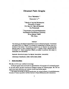
be defined by a pair L = (M, x) where M is a “patch” of terrain (representing a small area of the world) and x : M → IR2 are coordinate functions defined on M (where x is a diffeomorphism and we assume that the robot is moving on a two-dimensional surface). By convention, the landmark location will be at the origin of the coordinate system x−1 (0) ⊂ M . We will categorize navigation tasks in two broad classes. The first involves motion control near a landmark Li = (Mi , xi ). For example, a robot might move from one side of a hill to the opposite, or from one room to another through a doorway. Throughout the task, the robot remains within the map Mi surrounding the landmark. Problems of this type can in principle be solved by path planning on the single map-coordinate system pair (Mi , xi ), assuming that the robot can use its sensors to localize itself within Mi . In the following we will focus on a second class of navigation tasks which involve steering the robot from one landmark L1 to another L2 when M1 ∩ M2 = ∅ and the terrain separating L1 from L2 is only approximately known. III. Robots as Kinetic State Machines We have in mind that there is an underlying physical system (a robot in this case) outfitted with a set of sensors and actuators. At the lowest level, the system is modeled by a so-called kinetic state machine depicted in Fig. 1 [15]. The robot is governed by a
p
p
T
ξ
b
T
ξa
T
ξ
U ( t, x )
b
a
I
S(t)
II PREPROCESSOR
⋅ x(t)=f(x)+G(x)U SENSORS
KINETIC STATE MACHINE
Fig. 1. The kinetic state machine (from [15]).
differential equation of the form x˙ = f (x) + G(x)U ;
y = h(x) ∈ IRp
(2)
where x(·) : IR+ → IRn , U (·) : IR+ × IRn → IRm and G is a matrix whose columns gi are vector fields in IRn . The robot has access to a set of timers Ti and can evaluate a set of boolean functions ξi : IRp → {0, 1} defined on the space of sensor outputs. An input U (x, t) is to be thought of as a general feedback law which can be suspended by the interrupt functions ξi or timers Ti .
IV. Landmark-to-Landmark Navigation and Control In this work the available hardware (a Nomadic Technologies robot) allowed us to create landmarks relatively easily by exploring a particular location and storing sensor and position information. The local map associated with each landmark was a 150in. × 150in. grid (detailed in Sec.VI). Within such small areas odometry errors were small and the resulting maps were relatively accurate. Mapping larger areas is difficult due to the need to register new sensor data against an existing map (in the presence of positional uncertainty and - if outdoors - terrain curvature) and by the memory storage and time requirements of such a task. For these reasons, we want to avoid having to relate distant features geometrically. Instead, an ordered pair of landmarks will be associated with a set of “directions” for getting from the first landmark to the second. Towards that end, the extended Motion Description Language (MDLe) is used to encode these directions on a set of robot-independent control primitives (to be defined shortly). MDLe is a language for hybrid motion control which allows one to compose complex, interrupt-driven control laws from a set of simple primitives and syntactic rules [15], [16]. The goal of MDLe is to provide a way of writing hybrid control programs which - when properly interpreted - would produce the same results in the presence of uncertainty or in different systems. Early work on motion description languages was initiated by Brockett [17], [18]. Further work [15] resulted in the development of the extended motion description language, MDLe, and its recent Linux-based implementation [16] which this work is based upon. For a more complete description see [15], [17]. Related work in the use of abstract languages for hard real-time periodic control can be found in [19]. MDLe programs can be used to describe geographical relationships not in terms of where a location is but what one must do to get there. Apart from being robot-independent, such descriptions incorporate feedback which reduces the complexity of the control program required to perform a task [20]. A. Control programs in MDLe MDLe programs are strings that can be interpreted by a kinetic state machine. These strings can be thought of as control primitives which are “executed” in a sequence determined by their order of appearance in the program and by a set of interrupt conditions. The simplest MDLe program is an atom: σ = (U, ξ, T ) where U (x, t), ξ are as defined in Sec.III and T ∈ IR+ denotes time (measured from the moment the atom was activated) at which the atom will “time out”. To
evaluate or run the atom σ means to apply the input U to the kinetic state machine until the interrupt function ξ goes “low” (0) or until T units of time elapse, whichever occurs first. T is allowed to be ∞ and U may be an open loop or feedback control law. MDLe atoms can be composed into longer strings with their own interrupt functions and timers. Such strings are called behaviors. For example, one could use the atoms σ1 = (U1 , ξ1 , T1 ), σ2 = (U2 , ξ2 , T2 ) to define the behavior b = ((σ1 , σ2 ), ξb , Tb ). Evaluating b means evaluating σ1 followed by σ2 as long as the interrupt function ξb is “high” and less than Tb units of time have elapsed. Behaviors themselves can be nested to form higher-level strings. We will use the term plan to refer to an MDLe program. Although MDLe strings are sequential, the order of execution of atoms in a plan does not have to coincide with their order of appearance in that plan. This is a consequence of allowing for interrupts (triggered by external or internal events) as well as loops and gives MDLe significant expressive power. For a complete description of MDLe’s syntax and implementation, see [16]. A.1 Examples of MDLe atoms The Nomadic Technologies robot which was used as a testbed for this work has two actuated wheels and is kinematically equivalent to a unicycle. Its equations of motion are x˙ = y˙
=
θ˙
=
u1 + u2 cos θ 2 u1 + u2 sin θ 2 u1 − u2 d
(3)
where (x, y, θ) describe the position of the robot in SE(2), u1 , u2 are the left and right wheel velocities and d is the wheel separation. The robot has 16 sonar sensors r0 , ..., r15 around its perimeter, numbered in a clockwise direction, at angles θk = 2πk/16 with respect to an orthonormal coordinate frame whose y axis points forward and is parallel to the robot’s wheels. Each sonar returns range information on objects located within its 45o cone. The robot is also surrounded by touch sensors for detecting contact with obstacles. Some of the interrupt conditions which are currently implemented include: • (bumper): returns 0 when the robot’s bumper tape detects contact, 1 otherwise. • (wait τ ): returns 0 if τ seconds have passed after an atom has begun to run, 1 otherwise. • (atIsection b), where b is a 4-bit binary number: Returns 0 when the sonar sensors detect obstacles (or absence thereof) in 4 principle directions with respect to the current orientation of the robot. Each digit in
b selects whether the corresponding direction should be obstacle-free or not in the order (MSB to LSB): front,left,back,right. Used mainly to detect arrival at intersections. The following are examples of MDLe atoms which have been implemented together with their constituent control laws and interrupt conditions. Their syntax is: (Atom (interrupt condition) (control law)). Under our previous definitions an atom (U, ξ, T ) in the formal language is programmed as: (Atom (ξ OR t ≥ T ) (U )) • (Atom (wait ∞) (rotate α) ): u1,2 = ±k(α − θ). Causes the robot to make its orientation α with respect to its current coordinate system. • (Atom (bumper OR atIsection(b)) go(v,ω)): u1,2 = v ± ωd/2. Causes the robot to move with speed v cm/sec and turn rate ω rad/sec until it comes into contact with an obstacle or it arrives at an intersection specified in b. • (Atom (wait T) goAvoid(ψ, kf , kt )): u1,2 = uf ± (ut d)/2. Causes the robot to move with heading ψ in the absence of nearby obstacles. If there are objects close to the robot then the desired heading is altered to circumvent them: uf dm
= =
ut
=
kf dm (t) (4) min(r0 (t), . . . , r3 (t), r13 (t), . . . , r15 (t)) (5) �� � i ai sin θi (t)ri (t) � kt (ψ + atan − θ)(6) i bi cos θi (t)ri (t)
where ai , bi ∈ IR are a set of tunable parameters. (Atom (ri (t) == rj (t)) (align ri rj )): u1,2 = ±k(ri (t) − rj (t)). Causes the robot to rotate until sonars i and j return equal ranges. Used to align the robot at a given orientation with respect to walls and other obstacles.
•
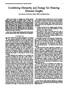
V. Towards a Directed Graph Representation of the World We now describe a structure which incorporates landmarks (as defined in Sec. II) and navigation directions written as MDLe plans. The proposed map architecture arranges landmarks in a directed graph G = {L, E} where L is the set of vertices and E the set of edges of the graph. Each vertex Li corresponds to a landmark together with its associated local map and coordinate system (Mi , xi ). A directed edge from Li to Lj is specified by the ordered quadruple Eij = {i, j, R, Γ} where i, j specify a pair of vertices and Γ is an MDLe plan that if executed while the robot is within the region R ⊂ Mi , will cause it to stop at a point inside Mj . Edges are directed because we do not expect that the same set of instructions will work for going back from Lj to Li .
A possible map is shown in Fig. 2. Within each
Fig. 2. A partial map structure
vertex the local maps Mi are depicted as occupancy grids. The presence of a connecting edge between a pair of landmarks Li and Lj indicates knowledge of navigating from one to the other, by evaluating a corresponding MDLe string, Γji . Of course, the graph need not be fully connected. No explicit information is stored regarding the relative positions of the landmarks and no global coordinate system is defined. The idea is to replace - when possible -the details of a map locally by a feedback program. One may arrive at such a program via prior exploration, planning or appropriate encoding of a portion of a map. A graph might be modified by adding or deleting landmarks and appropriately modifying some of its edges. A landmark may be added by mapping some area of terrain and associating the resulting information with a new vertex on the graph. If the instructions in Eij are unreliable due to the complexity of the intermediate terrain, we may refine Eij by (7) Eij → Eik , Lk , Ekj essentially “splitting” the plan Γji into two shorter ones. A complementary operation deletes a landmark that is no longer needed Eik , Lk , Ekj → Eij
(8)
where we have assumed that Eij , Ejk are the only two edges leading to and from Lj . The operations defined in Eqs. 7,8 may require modification to the two plans when the map between them is deleted (Eq.8) or to the initial plan before splitting it (Eq.7). VI. Experimental Results To demonstrate the construction and use of the map structure discussed in the previous section, we performed a simple indoor navigation experiment using
lab (Lab 2) were encoded in the MDLe plan: Γlab1 = lab2 (Atom (Atom (Atom (Atom (Atom (Atom (Atom (Atom }
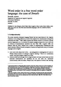
Fig. 3. Evidence grid surrounding Landmark 1: Front lab door (150 × 150 cells); the dimensions of each grid cell are 1in × 1in. Gray levels indicate the probability of a cell being occupied (0 for white and 1 for black).
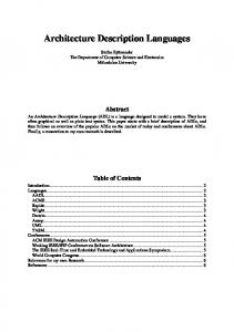
an indoor mobile robot. The goal of the experiment was to create a map which would allow the robot to repeatably and safely navigate between three locations in a building, all on the same floor. Three landmarks were defined, one around each of two doors to a lab and one around an office entrance. We used evidence grids [21] to describe local maps around landmarks. Terrain was represented by an array of cells together with the probability that each cell is occupied (ranging from 0 if a cell is sure to be empty to 1 if certainly occupied). To inform the local map associated with a landmark the robot moved around the landmark while collecting sensor data. That data were used to update the probability of occupancy of each cell in the grid using Bayes’ rule. The resulting evidence grids for the office and lab locations are shown in Figs. 3,4-a,4-b. The coordinate systems associated with each land-
(a)
(b)
Fig. 4. Evidence grid surrounding (a) Landmark 2: Office door and (b) Landmark 3: Rear lab door (150 × 150 cells). Cell dimensions are 1in × 1in.
mark were chosen to be orthonormal, with their origin at the center of each of the doorways. The control inputs to drive the robot from the rear of the lab (Lab 1) to the front of the
{ Lab2ToLab1Plan (bumper) (atIsection 0100) (goAvoid 90 40 20)) (atIsection 0010) (go 0 0.36)) (wait ∞) align 7 9) (atIsection 1000) (goAvoid 0 40 20)) (atIsection 0100) (go 0 0.36)) (wait ∞) align 3 5) (wait 7) (goAvoid 270 40 20)) (atIsection 1000) (goAvoid 270 40 20))
where the atoms and behaviors are defined in Section IV-A.1. Γlab1 lab2 can be executed when the robot is anywhere in the hallway, i.e. Rlab2 = {(x, y, θ) : x > 0, π < θ < 2π}. This plan takes the robot through the halls around the lab rather than through the lab itself. A plan that steers the robot from the front of the lab to the office is given by f ice Γof lab (Atom (Atom (Atom (Atom (Atom }
= { Lab1ToOfficePlan (bumper) (atIsection 1001) (goAvoid 90 40 20)) (atIsection 0011) (go 0 0.36)) (wait ∞) align 11 13) (atIsection 0100) (goAvoid 180 40 20)) (wait 10) (rotate 90));
Similar plans were created to fully connect the graph. These plans are not unique but they are fairly simple, and also quite similar to the set of directions one might give to someone unfamiliar with the floor layout. For f ice can be read as: “walk down the hallexample Γof lab1 way until you come to a corner, turn left, walk to the first open door on your right, turn right”. When asked to go from landmark i to landmark j the robot checks for the existence of a connecting path in the graph (in this case an edge connecting the two landmarks in the specified direction), retrieves Γji from the graph, and executes it by interpreting each of its atoms into control signals that actuate the wheels. In figure 5 we show the graph structure, two of the connecting edges, and a blueprint (not to scale) of the environment along with a typical path produced by of f ice the execution of Γlab1 lab2 followed by Γlab1 . On the lab1 path produced by Γlab2 an obstacle in the hallway (not indicated on the blueprint) caused the robot to temporarily move away from the wall. VII. Conclusions We have proposed a new, efficient map representation which is aimed at enabling robotic exploration and navigation in a wide range of environments. Relevant or interesting areas of the environment are stored in a graph whose vertices are landmarks, linked pairwise by language-based descriptions of control for landmark-
References [1]
[2]
[3]
[4] [5] Fig. 5. Three vertex graph containing the office and lab landmarks and the environment floor plan
to-landmark navigation. Our preliminary experimental results suggest that the proposed map representation is most useful when distinguishable terrain features are sparsely distributed or when most features are irrelevant to the robot’s task. One of the advantages of our approach is the use of MDLe strings to encode instructions for steering between landmarks. For the programs used in our experiment, we described some of the “atoms” used to implement those programs on our robot. For different robots, each atom’s control law and interrupt might have to be modified, however the MDLe programs stored in the map would be unchanged. This would be akin to re-writing a set of device drivers for use in a different computing platform. As part of our ongoing work, we are investigating ways of identifying landmarks from sensor data (a kind of state estimation problem) and automating the process of creating new landmarks. The latter problem might involve starting from a known location and exploring the environment while recording the MDLe strings which brought the robot to its present position. We expect to report soon on more comprehensive indoor navigation experiments, using a map with multiple landmarks, ultimately covering our entire building. Other related open problems include graph-level path planning by selecting from the available set of MDLe strings, as well as augmenting that set to include new strings which are found to be effective according to some appropriate metric. Other interesting extensions of this work might include a treatment of environmental or sensory uncertainty and the propagation of probability densities on a graph under the “action” of MDLe plans. VIII. Acknowledgments The authors would like to thank P. S. Carlos and R. E. Braud for their help in developing MDLe software.
[6]
[7]
[8]
[9] [10]
[11] [12] [13] [14] [15]
[16]
[17] [18] [19]
[20] [21]
S. Thrun, M. Beetz, B. Bennewitz, W. Burgard, A.B. Cremers, F. Dellaert, D. Fox, D. Hahnel, C. Rosenberg, N. Roy, J. Schulte, and D. Schulz. Probabilistic algorithms and the interactive museum tour-guide robot Minerva. IJRR, 19(11):972–99, 2000. A.T. deAlmeida and O. Khatib. Helpmate(r), the trackless robotic courier: a perspective on the development of a commercial autonomous mobile robot. In Autonomous Robotic Systems, pp. 182–210, 1997. A.H. Mishkin, J.C. Morrison, T.T. Nguyen, H.W. Stone, B.K. Cooper, and B.H. Wilcox. Experiences with operations and autonomy of the Mars Pathfinder Microrover. In IEEE Aerospace Conf. Proc., pp. 337–51, 1998. D. Hristu-Varsakelis. Robot formations: Learning minimum-length paths on uneven terrain. In Proc. IEEE Mediterranean Conf. on Control and Automation, 2000. R. Sim and G. Dudek. Mobile robot localization from learned landmarks. In Proc. IEEE/RSJ Int. Conf. on Intelligent Robots and Systems, pp. 1060–1065, 1998. A. Bandera, C. Urdiales, and F. Sandoval. Autonomous global localisation using Markov chains and optimised sonar landmarks. In Proc. IEEE/RSJ Int. Conf. on Intelligent Robots and Systems, pp. 288–293, 2000. B. Yamauchi. Mobile robot localization in dynamic environments using dead reckoning and evidence grids. In Proc. IEEE Int. Conf. on Robotics and Automation, pp. 1401–1406, 1996. A. Schultz, W. Adams, and B. Yamauchi. Integrating exploration, localization, navigation and planning with a common representation. Autonomous Robots, 6(3):293– 308, June 1999. N. Roy and S. Thrun. Coastal navigation for mobile robot navigation. In Proc. Conf. on Neural Information Processing Systems, 1999. D. Emerson. Landmark-based navigation by means of Bayesian landmark recognition. Undergraduate thesis, Division of Engineering and Applied Science, Harvard University, 2001. A. Lazanas and J.-C. Latombe. Landmark-based robot navigation. Algorithmica, 13(5):472–501, May 1995. A. Lambert and Th. Fraichard. Landmark-based safe path planning for car-like robots. In Proc IEEE Int. Conf. on Robotics and Automation, pp. 2046–2051, 2000. E. Fabrizi and A. Saffioti. Extracing Topology-Based Maps from Gridmaps. In Proc. IEEE Int. Conf. on Robotics and Automation, pp. 2972–2978, 2000. S. Thrun. Bayesian landmark learning for mobile robot localization. Machine Learning, 33(1):41–76, Oct. 1998. V. Manikonda, P. S. Krishnaprasad, and J. Hendler. Languages, behaviors, hybrid architectures and motion control. In J. Baillieul and J.C. Willems, editors, Mathematical Control Theory, pp. 199–226. Springer, 1998. D. Hristu, P.S. Krishnaprasad, S. Andersson, F. Zhang, L. D’Anna, and P. Sodre. The MDLe engine: A software tool for hybrid motion control. Tech. Report 2000-54, Institute for Systems Research, 2000. R. Brockett. Formal languages for motion description and map making. In Robotics, pp. 181–193. American Mathematical Society, 1990. R. Brockett. On the computer control of movement. In Proc. 1988 IEEE Conf. on Robotics and Automation, pp. 534–540, 1988. T. Henzinger, B. Horowitz, and C. Kirsch. Giotto: a timetriggered language for embedded programming. In Proc. First Int’l Workshop on Embedded Software, Lecture Notes in Computer Science. Springer-Verlag, 2001. M. Egerstedt and R. Brockett. Feedback can reduce the specification complexity of motor programs. IEEE Trans. Robotics and Automation, submitted. M. Martin and H. Moravec. Robot evidence grids. Tech. Report CMU-RI-TR-96-06, The Robotics Institute, Carnegie Mellon University, 1996.