as automated lawn mowing and vacuum cleaning. Our objective in this paper is to perform area coverage using low-cost but limited capability mini-robots. The.
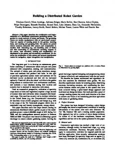
Distributed Area Coverage Using Robot Flocks Ke Cheng, Prithviraj Dasgupta and Yi Wang Computer Science Department University of Nebraska, Omaha, NE, USA E-mail: {kcheng,ywang,pdasgupta}@mail.unomaha.edu
Abstract We consider the problem of distributed, autonomous area coverage using a team of mobile mini-robots that have limited sensing and computation capabilities. Specifically, we investigate the following hypothesis - can mini-robots organized in small teams improve the efficiency of area coverage as compared to area coverage using robots that are not organized as teams? We envisage that team formation for mini-robots can be realized through simple, nature-inspired formation control algorithms such as flocking. We provide coordination mechanisms between robots that allow the robots forming a team to dynamically correct their relative position and move in formation, as well as, to dynamically adapt their position and orientation on encountering an obstacle. We have extensively tested our formation control mechanism and area coverage algorithm using accurate models of e-puck robots within the Webots robot simulator, as well as on physical e-puck robots. Our results indicate that our teambased area coverage technique achieves comparable coverage with lower overhead with respect to other distributed area coverage mechanisms for mini-robots.
1. Introduction Over the past few years, distributed area coverage of an unknown environment has emerged as an important direction in mobile robotics. The objective of the area coverage problem is to ensure that every portion of the environment is covered by the coverage sensor of at least one robot. To ensure efficient coverage, the total time or energy spent in performing the coverage and the overlap between the regions covered by different robots should also be reduced. Area coverage by robots is used in various domains such as unmanned search and rescue, automated inspection of engineering structures [5] and even for domestic applications such as automated lawn mowing and vacuum cleaning. Our objective in this paper is to perform area coverage using low-cost but limited capability mini-robots. The
advantage of using mini-robots is the economy of fielding the robot team due to the relatively low cost of each robot and the robustness of the system offered by the large number of robots. However, the limited capability of the robots also prevents using complex techniques for controlling these robots. Many researchers have proposed distributed area coverage algorithms that enable robots to cover an unknown environment and an excellent overview is given in [4]. Our work focuses on area coverage algorithms that can be used for limited capability ant-like robots [7], [11]. In each of these techniques, the robot control algorithm is inspired by very simplistic motion patterns and coordination observed among social insects in nature. We investigate whether the coverage achieved by these techniques can be improved if robots can be coordinated to move together in small teams while covering the environment. A popular nature-inspired, emergent technique for controlling the movement of multiple robots organized as teams is provided by the flocking or herding behavior of birds and animals. In this paper, we describe techniques that enable limited capability mini-robots to cover an unknown environment in a distributed manner by forming multiple small-sized teams and to dynamically adapt their formation within a team on encountering an obstacle. We have tested our techniques on the Webots simulation platform using accurate models of e-puck robots as well as on physical e-puck robots. Our experimental results show that our team-based coverage techniques for distributed area coverage can perform comparably while lowering storage and communication overhead with respect to coverage strategies where mini-robots are coordinated individually.
2. Related Work Most research on formation of robot-teams using distributed techniques has been inspired by Reynolds’ seminal work on the mobility of flocks[10] which prescribes three fundamental operations for each robot to realize distributed flocking - separation, alignment
and cohesion. Following Reynolds’ model, several authors [1], [2], [12] describe mechanisms for robot-team motion while maintaining specific formations where individual robots determine their motion strategies from the movement of a team leader or neighbor(s). Fredslund and Mataric[6] describe techniques for robot team formation without using global knowledge such as robot locations, or the positions/headings of other robots, and use little communication between robots. Robot team formation using mini-robots has been addressed by Hanada et al.[8] using motion models from schooling of tuna fish. However, robots in their system rely extensively on accurate visual sensing. Swarmingbased multi-robot coordination techniques applied to area coverage [5], [13], usually focus on controlling robots individually. In contrast, here we propose to address the area coverage problem where robots are coordinated as a team instead of being coordinated individually.
3. Flocking-based Area Coverage We consider a set of R robots placed within an initially unknown environment. Each robot has two wheels and forward-facing IR-based distance sensors. Each robot is also capable of local communication with other robots over a Bluetooth connection. To enable robots form a team we have used a formation control mechanism inspired by Reynolds’ flocking model. Each team identifies a unique robot called the team’s leader. The leader robot follows the path prescribed to it by the coverage technique described below. Because the leader is the foremost robot in a team in the direction of the team’s motion, therefore, the leader robot is likely to encounter an obstacle, if any, before the other following robots in the team. Based on the perceived direction of the obstacle detected on its distance sensors, the leader adjusts the team’s formation to avoid the obstacle and possibly relinquishes leadership to another team member. The leader coordinates the motion of the rest of the team members using the formation control mechanism described below. Leader-Referenced Motion. To move the robots belonging to a team in a coordinated manner, each robot uses a leader-referenced strategy. In this strategy, the leader communicates its current action to each of the team members. These team members then execute the action prescribed by the leader. If any team member is unable to perform its prescribed action, it communicates its inability to perform the action to leader. The leader then takes a corrective action so that the team can continue to move together while covering the environment. If a robot is not the team leader, it is called a follower robot. A follower robot receives
4 2 0 3 1 1 ß
3 0 -ß
2 4
Figure 1.
A team of five robots encountering an
obstacle.
the action communicated to it by the team leader as the prescribed action for the current time step. The follower robot then attempts to perform this action. If the follower robot fails to execute this action, it stops and informs the leader that its action failed. For example, if one of the follower robots encounters an obstacle that the team leader did not encounter then the follower robot stops and informs the team leader that it failed to follow the direction corresponding to the team leader’s motion. Depending on the location of the follower robot in the team, the team leader then selects an action that would possibly alleviate the action failure for the affected follower robot. The team leader then broadcasts this newly selected action as the prescribed action for the next time step to all the follower robots in the team. In some scenarios, due to communication noise, a follower robot might fail to receive the communication containing the prescribed action from the leader robot. Then the follower robot just repeats the action it performed during its previous time step. If the leader robot fails the team followers abort trying to communicate with the leader after a certain time window and inform each other about a leader failure. The follower robots then select the new leader robot from amongst themselves as the robot that has the shortest distance cumulative distance to all other follower robots. Obstacle Avoidance. A leader robot executing the leader-referenced behavior can fail to perform an action if the robot encounters an obstacle on its distance sensors. A scenario illustrating this situation is shown in Figure 1 for the robots moving in a V-shaped formation. The robots are represented as solid circles and the team leader is denoted by the robot at position 0. As shown in the figure, the team was moving leftwards before encountering the obstacle. As soon as the obstacle is encountered by the team leader’s distance sensor, the team leader stops and executes the obstacle
avoidance method. This method causes the team to elect a new leader and adjusts the locations of the robots in the team to enter into a new formation with respect to the newly elected leader. The adjustments performed by the team members after the team leader at position 0 encountered the obstacle is shown the dashed-circles in Figure 1. For example, the adjustment in the positions of the robots after selecting the robot originally at position 3 as the leader are given by: old position 0 moves to new position 4, old position 1 moves to new position 2, old position 2 moves to new position 1, old position 3 moves to new position, and, old position 4 moves to new position 3. In general, the positional adjustments of the robots after its team leader encounters an obstacle is given by: n if i = 0 pi = n − i − 1 if i is odd number n − i + 1 if i is even number
where n is the number of robots in team minus 1, i is the old position in the team, and pi is the new position in the team. After getting in the new formation, the new leader selects a new heading given by a random value in the range of ±β as shown in Figure 1. This results in the team performing a π ± β turn to avoid the obstacle encountered during its movement. Figure 1 illustrates a scenario when the original leader robot encountered a wall directly ahead of it. In general, if the wall is encountered by the old leader using its forward-facing distance sensors on its right-hand side (clockwise from current heading), then the follower robot that is farthest from the leader on its right-hand side (robot originally at position 4 in Figure 1) is selected as the new leader. Similarly, if the old leader robot determines the obstacle on its left-hand side, then the follower robot that is farthest from the leader on its left-hand side (scenario illustrated in Figure 1) is selected as the new leader. If the old leader robot approaches the obstacle tangentially resulting in comparable readings on both pairs of the forward-facing (left and right) distance sensors, then one of the two follower robots that is farthest from the old leader robot is selected at random to become the new leader. Formation Maintenance. When a team of robots moves in formation, the noise in the wheel rotation and sensor readings can cause one or more of the team members to lose their positions and destroy the configuration in the team. To address this problem, we have used a broadcast-based protocol to enable each team member retain its position in a team and maintain the formation of the team. To maintain the team formation, the team leader first calculates the desired positions (DPi ) of every team member i
a
0 d
u
1 2 3 i
4
Figure 2. A ’V’-shape formation in a team showing the heading of the leader at an angle a and an angular separation of 2 × u between the follower robots on either side of the leader.
relative to its own position. Next, it compares DPi with the actual position APi of each team member. If the distance between DPi and APi is greater than d, the distance between two adjacent robots or n times of d, for any team member i, the team leader sends a message to robot i with its desired position DPi , and, sends a message to all other team members to stop. After robot i has reached DPi , the team leader sends a message to every team member to continue moving in its previous direction before the formation maintenance. The method for calculating DPi is shown in Figure 2. The current heading of the team is in the direction shown by a while the angle between the followers on the left and right-hand sides of the team leader is denoted by 2 × u, where u ∈ [0, π]. If u is equal to 0 or π, the formation becomes the line formation. The distance between two adjacent robots is d. The actual position APi and the desired position DPi for robot i are denoted by (x0 , y0 ) and (xi , yi ) respectively. The calculation of DPi is given below: (a) Case 1: 0 ≤ a < π � if i is odd number x0 − 2i × d × cos(a − u) xi = x0 + 2i /2 × d × cos(a − u) if i is even number yi = y0 − 2i × d × sin(a − u) (b) Case 2: π < a ≤ 2π � if i is odd number x0 + 2i × d × cos(a − u) xi = x0 − 2i /2 × d × cos(a − u) if i is even number yi = y0 + 2i × d × sin(a − u) Coverage Technique. A robot team using the formation control mechanism described above uses a very simple technique to cover the environment. In this technique, each leader robot uses a Braitenberg-motion based coverage strategy to cover the environment - the leader (and the following team members) move along a straight line until it encounters an obstacle. The leader robot then uses the obstacle avoidance mechanism described above to readjust the formation of the team and a new leader is selected to continue the coverage.
Table 1. Percentage of of a 5 × 5m2 environment covered for different environment shapes and different coverage strategies.
(a)
(c)
(b)
(d)
Figure 3. four different environments of five robots with V shape in Webots simulation platform: (a) a square, (b) a triangle, (c) a corridor, (d) two diamonds connected by a corridor.
4. Experimental Results We have evaluated our team-based, multi-robot, formation control strategies for area coverage using accurate models of e-puck robots within the Webots robot simulator and on physical e-puck robots. An epuck robot has a diameter of 7 cm and a memory capacity of 144 KB including RAM and Flash memory. Each wheel is 4.1 cm in diameter and is capable of a maximum speed of about 12cm/s. We have used the following sensors that are available on the e-puck robot: (1) Eight infra-red distance sensors measuring ambient light and proximity of obstacles in a range of 4 cm (2) Bluetooth capability for wireless communication. Simulation in Webots. We used four different environments for our simulations - square, triangle, corridor, and two diamonds connected with a narrow corridor, as shown in Figure 3 . All these environments have the same area of 25 meter2 . In each environment, we placed 3, 5 or 10 robots that were organized into 1 or 2 teams. By combining these parameters, we tested our coverage strategies in 16 different experiment scenarios. Each experiment scenario was allowed to run over a duration of 2 hours. Each result was averaged over 10 simulation runs. For evaluating our results, we have compared the performance of four different coverage strategies: (1) Individual coordinated or formation-less strategy. This strategy is similar to the node counting and pheromone-based coverage strategy described in [9]. The individually coordinated coverage strategy is used by independently moving robots (that
Coverage Strategy individual coor. line flocking ’V’ flocking hybrid flocking
Square 64.74 51.05 40.33 42.96
individual coor. line flocking ’V’ flocking hybrid flocking
83.36 58.17 62.83 59.91 10 93.27 82.8 76.6 81.77
individual coor. line flocking ’V’ flocking hybrid flocking
3 robots in 1 team Triangle Corridor Two diamonds 61.98 45.05 39.9 48 45.76 45.88 41.92 46.06 31.33 42.48 47.45 41.46 5 robots in 1 team 78.85 55.16 52.05 56.14 34.92 44.09 55.44 40.37 40.26 57.41 37.08 43.42 robots in 2 teams of 5 robots each) 84.53 73.37 75.88 78.2 66.57 74.38 81.23 57.38 73.63 79.3 58.66 62.17
is, robots not moving as a team in formation). This coverage strategy involves storage and computation overhead as each robot records a finite history of the region covered by it and exchanges and fuses this information with robots within its communication range. We have used a slightly modified version of this algorithm suitable for e-puck robots described in [3]. (2) Line-shape Formation. In this coverage strategy, robots form teams with a straight line configuration. (3) ’V’ shape Formation. Here, robots form a Vshaped configuration using the techniques described in Section 3, and, (4) Hybrid Formation. In this technique, robots dynamically alternate between the line formation and V-formation while regaining configuration after the team’s shape transformation. To compare the relative performance of these strategies for the different environments and different numbers of robots, each simulation was allowed to run for a period of almost 2 hours that corresponds to the maximum battery life of an e-puck robot. Our objective in the experiments we performed was to investigate how much of the environment could be covered within the battery life of each robot-team. Although not shown here, each environment was completely covered when the simulations were allowed to run for 2.5 hours (with 10 robots) to 4 hours (with 3 robots). For each simulation, all robots were deployed from the center of each environment. The results of our simulations for the area coverage of the different scenarios is summarized in Table 1. Each value in Table 1 represents the percentage of the environment that was covered by the robots at the end of 2 hours of simulation time. We observe that the three
flocking-based techniques perform comparably with the individual coordinated strategy. The extra overhead of the flocking-based techniques can be attributed to the extra time required by the flocking-based methods for formation maintenance and for reconfiguring the team after encountering an obstacle. However, as we increase the number of robots, the coverage achieved using the three flocking-based techniques improves with respect to the individually coordinated strategies. We also observe that for more complex environments such as the corridor and the non-convex environment with two diamond-shapes connected by a corridor, the line formation obtains the best coverage among the flocking-based coverage techniques, followed by the hybrid formation. This can be attributed to the fact that in a line-formation, the robot teams are able to traverse narrow passages such as corridors more efficiently. On the other hand, in a V-formation the angular dispersion of 2 × u between the two sets of follower robots (shown in Figure 2) impedes the movement of the team in narrow spaces. Finally, because in the hybrid formation the robots alternate between a line and V-shape formation, therefore, the hybrid formation achieves a coverage between the line and V-shape formations. We also observe that when we increase the number of teams from one team of 5 robots to two teams of five robots the coverage does not improve linearly. This is because the robots cannot remember the regions covered by themselves or by other teams in the past. Therefore, they end up re-covering regions already covered in the past. To further analyze the performance of the flockingbased techniques we have compared the average time spent by the different formations in the flocking-based techniques for reconfiguring after avoiding an obstacle and for performing formation maintenance. The results of these experiments are reported for one 5-robot team for the different environments in Figures 4 (a)-(d). In Figure 4(a), we observe that the number of obstacles encountered by the robots using different formation control strategies depends on the shape of the environment. However, as shown in Figure 4(b), the lineformation requires very little time for reconfiguration because of its simpler configuration shape. On the other hand, the V-shape requires the longest reconfiguration time to accurately determine the positions of the different followers robots along the two arms of the V-shape. Finally, the hybrid formation requires slightly lesser reconfiguration time than the V-shape because sometimes the obstacle might be encountered when the robots are in a line formation. Figures 4(c) and (d), show the corresponding number of formation maintenance operations and the average time required
to perform a formation maintenance operation. The formation maintenance operations reported here include both the selection of a new action by the leader to alleviate a failed action by a follower robot as well as the position adjustment operations performed by the follower robots described in Section 3. We observe in Figure 4(c) that the number of reformations for the square and triangle environments is larger. This can be attributed to the fact that the free space in these two environments is larger and the robot team can travel in the same direction without encountering any obstacle. During continuous motion in the same direction, the follower robots get out of their desired positions required for the configuration due to noise in the wheel motion. Therefore, more time the maintenance formation is invoked more often in these two environments. However, in the corridor and diamonds environment, the robots are in a narrow passage and they frequently encounter obstacles which causes them to adjust their positions through team reconfiguration instead of performing formation maintenance. The average time required by the line-shape formation for performing formation maintenance is also the highest, as shown in Figure 4(d). This can be attributed to the fact that when robots use the line formation they are moving in a single flank. Therefore, multiple robots are likely to require formation maintenance when one of the follower robots fails to perform an action. Consequently, the leader robot expends more time to find an action that will alleviate the failure to perform an action for multiple follower robots. Evaluation on Physical Robots. We tested our methods in an indoor lab environment with 3 epuck robots in a 2.44 × 1.22 m2 rectangular arena. For localizing the robots, we have used an overhead camera-based localization system that mimics the functionality of a GPS. We used a Logitech QuickCam Orbit AF with a 960 × 720 resolution and capable of 5 frames/sec. We used the Roborealm software to perform image processing operations. Each experiment was run for 15 minutes and results were averaged over 5 runs. Figure 5(a) shows the control windows of Roborealm. To improve the recognition results and reduce noise, we made the ground and walls of the environment white in color. Moreover, we built a cover for each e-puck using a blue, red, or green triangle to denote its location and heading clearly within the image captured by the overhead camera, as shown in Figure 5 (b). We performed coverage within our test environment using both the individual coordinated strategy and the ’V’-shape formation. We observed that the individually coordinated strategy has about 10% to 15% more coverage than the ’V’ shape method in
Wait time of each obstacle avoidance(s)
Number of obstacle avoidance
30 Line Shape V shape Hybrid
25
20
15
10
5
0
1
2
3
5. Conclusions and Future Work
1000
4
Line shape V shape Hybrid
900 800 700 600 500 400 300 200 100 0
1
Type of environments
2
3
4
Type of environments
(a)
(b) 35 Line shape V shape
Line shape V shape Hybrid
Number of reformation
60 50 40 30
Wait time of each reform(s)
30 70
Hybrid 25
20
15
10
20 5 10 0 0
Square
Triangle
Corridor
Diamonds
1
2
3
4
Type of environments
Type of environments
(c)
(d)
Figure 4.
(a) Number of times an obstacle is encountered by the team, (b) Average time required for team reconfiguration after encountering an obstacle, (c) Number of times the team has to perform formation maintenance while not encountering an obstacle, and, (d) Average time required for formation maintenance.
(a)
(b)
Figure 5. (a)A photo of three e-pucks in V shape team on 1.22 × 2.44m2 real indoor arena, (b) The screen shot of three e-pucks with 1.22 × 2.44m2 indoor arena in the Roborealm user console.
15 minutes running time. The ’V’ shape formation performed an average of 4 reconfigurations during the coverage. The extra time required by the V-shaped formation is because of the time required to perform reconfigurations after encountering an obstacle and to perform formation maintenance. However, the Vshape formation achieved this comparable coverage without recording any coverage information while in the individual coordination technique each robot recorded its coverage history and exchanged it with other robots. Therefore, the formation-based technique achieved comparable performance as the individually coordinated technique at a lower computation and communication overhead.
In this paper, we have described techniques for flocking-based distributed multi-robot formations used for area coverage, and, to the best of our knowledge, this is one of the first papers in this direction. Our results show that the flocking-based team formation strategies perform area coverage comparably with the individually coordinated coverage strategy while using lesser computation and communication overhead. This work represents our first step in performing area coverage using robot teams organized in a multi-robot formation. In the future, we plan to analyze the robustness of our techniques in more complex and more noisy environments. We are also investigating techniques to improve the basic formation control mechanisms described in this paper using a utility-based model for dynamic team adaptations.
References [1] T. Balch and R. Arkin, “Behavior-based formation control of multi-robot teams,” IEEE Trans. on Robotics and Automation, vol. 14, no. 6, 1998, pp. 926-939. [2] Q. Chen and J. Luh, “Coordination and control of a group of small mobile robots,” ICRA 1994, pp. 23152320. [3] K. Cheng and P. Dasgupta, ”Dynamic Area Coverage using Faulty Multi-agent Swarms”, Intl. Conf. on Intelligent Agent Technology (IAT), Fremont, CA, 2007, pp.17-23 . [4] H. Choset, “ Coverage for robotics: A survey of recent results,” Annals of Math and AI, vol. 31, nos. 1-4, 2001, pp. 113-1756. [5] N. Correll and A. Martinoli, “Robust Distributed Coverage using a Swarm of Miniature Robots,” ICRA 2007, pp. 379-384. [6] J. Fredslund and M. Mataric, “A general algorithm for robot formations using local sensing and minimal communication,” IEEE Trans. on Rob. and Auton., vol. 18, no. 5, 2002, pp. 837-846. [7] Y. Gabriely and E. Rimon “ Spanning-tree based coverage of continuous areas by a mobile robot,” Annals of Math and AI, vol. 31, nos. 1-4, 2001, pp. 77-98. [8] Y. Hanada, G. Lee and N. Chong, “Adaptive flocking of a swarm of robots based on local interactions,” Swarm Intelligence Symposium (SIS), 2007, pp. 340-347. [9] S. Koenig, B, Szymanski and Y. Liu, “Efficient and Inefficient Ant Coverage Methods,” Annals of Math and AI, vol. 31, no. 1-4, 2001, pp. 41-76. [10] C. Reynolds, “Flocks, herds and schools: A distributed behavioral model,” Computer Graphics, vol. 21, no. 4, 1987, pp. 25-34. [11] I. Wagner, M. Lindenbaum, and A. Bruckstein, “Distributed Covering by Ant-Robots Using Evaporating Traces,” IEEE Trans. on Robotics and Automation, vol. 15, no. 5, 1999, pp. 918-933. [12] P. Wang, “Navigation strategies for multiple autonomous mobile robots moving in formation,” IROS 1989, pp. 486-493. [13] B. Yamayuchi, “Frontier based exploration using multiple robots,” Proc. 2nd Intl. Conf. on Autonomous Agents, Minneapolis, MN, 1998, pp. 47-53.