A mobile ad hoc Network (MANET) is a mobile mesh network in which mobile wire- less nodes are both ..... A secure OLSR protocol also uses digital signature to.
Distributed Intrusion Detection Models for Mobile Ad Hoc Networks By CHIN-YANG HENRY TSENG M.S. (Santa Clara University) 2002 B.A. (National Chiao-Tung University, Taiwan) 1998 DISSERTATION Submitted in partial satisfaction of the requirements for the degree of DOCTOR OF PHILOSOPHY in Computer Science in the OFFICE OF GRADUATE STUDIES of the UNIVERSITY OF CALIFORNIA DAVIS Approved By:
Karl N. Levitt, Chair
Matthew Bishop
Xin Liu Committee in Charge 2006 –i–
Distributed Intrusion Detection Models for Mobile Ad Hoc Networks
Copyright 2006 by Chin-Yang Henry Tseng
–ii–
Abstract A mobile ad hoc Network (MANET) is a mobile mesh network in which mobile wireless nodes are both hosts and routers so they can communicate without base stations. Because of this cooperative routing capability, MANETs have envisioned for military and emergency communication, but become more vulnerable to routing attacks than wired networks. If a malicious node propagates forged routing information in a MANET, the node can easily paralyze the network or hijack valuable routes. Due to MANET’s particular routing characteristics, defending routing attacks is challenging and critical in MANET. Traditional cryptographic authentication schemes are not sufficient due to insider routing attacks. Intrusion detection systems are ideal for insider attacks, but most of them are designed for wired networks and thus they can neither directly deploy in MANETs nor effectively detect new routing attacks in MANET. So we apply specification based intrusion detection approach that defines normal behavior of the protected networks to detect new routing attacks in MANETs. Therefore, we proposed a complete distributed intrusion detection system that consists of four models for MANETs with formal reasoning and simulation experiments for evaluation. We first proposed two specification based intrusion detection models for AODV (Ad hoc On-demand Distance Vector) and OLSR (Optimized Link State Routing), which are the two representative routing protocols in MANET. Second, we proposed a Distributed Evidence-driven Message Exchanging intrusion detection Model (DEMEM), which provides a practical distributed intrusion detection and message exchange framework. And we implemented DEMEM with three ID messages to provide reliable message exchange platform for intrusion detection in OLSR. Third, we proposed Distributed Routing Evidence Tracing and Authentication intrusion prevention model (DRETA). DRETA consists of a low computation overhead authentication and a scalable integrity protection of forwarded routing messages in MANETs. Finally, DRETA integrates our other three models into one complete intrusion detec–iii–
tion system for MANETs. To enhance this system, we are developing a cooperative intrusion response model that correlates nodes to generate global alarms for attacks. Besides, we plan to develop a detection model for tunneling attacks, which are the correlated attacks that this system cannot detect, and extend this system to support other routing protocols in MANETs.
–iv–
Acknowledgments I wish to express my greatest thanks and respects to my advisor, Professor Karl N. Levitt. Without his support and guidance, I am not able to finish this thesis. I especially appreciate his unforgettable encouragement and essential research principals for my research study. I am very grateful that he spent his precious time and energy for advising my works and presentations. Through him I have seen an ideal example as an enthusiastic researcher and patient advisor. I feel really lucky to be his student at UC Davis. I sincerely thank to Professor Matt Bishop and Professor Xin Liu, my dissertation committee members for their insightful guidance and valuable comments throughout my graduate studies. Furthermore, I appreciate great help and suggestions from Calvin Ko, Poornima Balasubramanyam, my qualifying exam committee members and dear partners in our IDMANET project. I also thank my friends in the Computer Security Laboratory, Computer Science Department, and Taiwan Graduate Student Association for their cherished friendship during my four years of Ph.D. study. I especially thank Rattapon Limprasittiporn, Chao Gui, and Tao Song for their helpful assistance and discussion of my research study. Here I would like to give my deep appreciation and thankfulness to my wife, ShiauHuey Wang. She always gives me timely support and participation for my research. She is also my critical and reliable teammate in my research study. Without her help and support, I cannot finish my works. Lastly and most importantly, I thank my parents for their constant and generous support for my Ph.D. study and career goals in US. And I would like to thank Lord Jesus Christ. He strengthens me to be able to resolve all kinds of problems and develop key ideas in my research.
–v–
Contents List of Figures
ix
List of Tables
xi
1 Introduction 1.1 MANET . . . . . . . . . . . . . . . . . . . . . . 1.2 Vulnerabilities in MANET . . . . . . . . . . . . 1.3 Cryptographic Approaches in Securing MANET 1.4 Intrusion Detection . . . . . . . . . . . . . . . . 1.5 New challenges of IDS in MANET . . . . . . . . 1.6 Contributions . . . . . . . . . . . . . . . . . . . 2 Related Works 2.1 Introduction . . . . . . . . . . . . . . . . . . . . 2.2 Authentication Approaches . . . . . . . . . . . . 2.3 IDS Approaches in Mobile Ad-hoc Net-works . . 2.4 Packet Dropping Detection . . . . . . . . . . . . 2.5 Specification based Intrusion Detection Systems
. . . . . .
. . . . . .
. . . . . .
. . . . . .
. . . . . .
. . . . . .
. . . . . .
. . . . . .
. . . . . .
. . . . . .
. . . . . .
. . . . . .
1 1 2 3 4 5 6
. . . . .
. . . . .
. . . . .
. . . . .
10 10 11 12 13 14
3 A Specification-based Intrusion Detection Model for AODV 3.1 Introduction . . . . . . . . . . . . . . . . . . . . . . . . . . . . . 3.2 Vulnerabilities In AODV . . . . . . . . . . . . . . . . . . . . . . 3.2.1 Overview of AODV . . . . . . . . . . . . . . . . . . . . . 3.2.2 Vulnerable Fields in AODV Control Messages . . . . . . 3.2.3 Examples of Single Attacks . . . . . . . . . . . . . . . . 3.2.4 Examples of Aggregated Attacks . . . . . . . . . . . . . 3.3 Specification-Based Monitoring of AODV . . . . . . . . . . . . . 3.3.1 Basic Assumptions . . . . . . . . . . . . . . . . . . . . . 3.3.2 Run-time Monitoring of Request-Reply Flow . . . . . . . 3.3.3 Finite-state Machine Constraints . . . . . . . . . . . . . 3.3.4 Matching Current and Previous Messages . . . . . . . . 3.3.5 Construction and Processing of Session Trees . . . . . . . 3.4 Examples . . . . . . . . . . . . . . . . . . . . . . . . . . . . . . 3.4.1 Tracing AODV Packets . . . . . . . . . . . . . . . . . . .
. . . . . . . . . . . . . .
. . . . . . . . . . . . . .
. . . . . . . . . . . . . .
16 16 17 17 19 20 21 23 24 24 26 28 31 34 34
–vi–
. . . . .
. . . . .
. . . . .
. . . . .
. . . . .
. . . . .
. . . . .
. . . . .
3.5
3.4.2 Detecting Simple Attacks . . . . . . . . . . . . . . . . . . . . 3.4.3 Detecting Aggregated Attacks . . . . . . . . . . . . . . . . . . Conclusion . . . . . . . . . . . . . . . . . . . . . . . . . . . . . . . . .
4 A Specification-based Intrusion Detection Model for OLSR 4.1 Introduction . . . . . . . . . . . . . . . . . . . . . . . . . . . . 4.2 OLSR Vulnerability Analysis . . . . . . . . . . . . . . . . . . . 4.2.1 Overview of OLSR . . . . . . . . . . . . . . . . . . . . 4.2.2 OLSR Vulnerability and Attacks . . . . . . . . . . . . 4.2.3 Attack Impact . . . . . . . . . . . . . . . . . . . . . . . 4.3 Intrusion Detection Model . . . . . . . . . . . . . . . . . . . . 4.3.1 Assumptions . . . . . . . . . . . . . . . . . . . . . . . . 4.3.2 Correct Behavior Model of OLSR . . . . . . . . . . . . 4.3.3 Temporary Inconsistency . . . . . . . . . . . . . . . . . 4.3.4 Limitations . . . . . . . . . . . . . . . . . . . . . . . . 4.4 Analysis of the OLSR Detection Model . . . . . . . . . . . . . 4.5 Simulation . . . . . . . . . . . . . . . . . . . . . . . . . . . . . 4.5.1 Simulation Environment . . . . . . . . . . . . . . . . . 4.5.2 Implementation of Detection mechanism . . . . . . . . 4.5.3 Example Attack Scenario and Results . . . . . . . . . . 4.5.4 Temporary Inconsistency against Mobility . . . . . . . 4.6 Conclusion . . . . . . . . . . . . . . . . . . . . . . . . . . . . .
. . . . . . . . . . . . . . . . .
. . . . . . . . . . . . . . . . .
. . . . . . . . . . . . . . . . .
. . . . . . . . . . . . . . . . .
36 36 37 38 38 40 40 41 42 43 44 44 46 48 48 52 52 53 54 60 62
5 DEMEM: Distributed Evidence-driven Message Exchange intrusion detection Model for MANET 64 5.1 Introduction . . . . . . . . . . . . . . . . . . . . . . . . . . . . . . . . 64 5.2 Threats and Challenges of MANET . . . . . . . . . . . . . . . . . . . 66 5.2.1 Threats of MANET . . . . . . . . . . . . . . . . . . . . . . . . 66 5.2.2 Attack Model . . . . . . . . . . . . . . . . . . . . . . . . . . . 67 5.2.3 Challenges vs. Requirements of IDS for MANET . . . . . . . 68 5.3 Distributed Evidence-driven Message Exchange intrusion detection Model 70 5.3.1 Distributed IDS Architecture . . . . . . . . . . . . . . . . . . 70 5.3.2 Intrusion Detection Layer . . . . . . . . . . . . . . . . . . . . 71 5.3.3 Evidence-Driven Message Exchange . . . . . . . . . . . . . . . 72 5.4 DEMEM in OLSR . . . . . . . . . . . . . . . . . . . . . . . . . . . . 74 5.4.1 Routing Attack Methods in OLSR . . . . . . . . . . . . . . . 74 5.4.2 Specification-based Intrusion Detection . . . . . . . . . . . . . 75 5.4.3 Implementing DEMEM in OLSR . . . . . . . . . . . . . . . . 76 5.4.4 ID-Evidence Message . . . . . . . . . . . . . . . . . . . . . . . 79 5.4.5 ID-Forward Message . . . . . . . . . . . . . . . . . . . . . . . 81 5.4.6 Tolerate Message Lost . . . . . . . . . . . . . . . . . . . . . . 83 5.4.7 Thwarting forged OLSR messages attacks . . . . . . . . . . . 85 5.5 Simulation . . . . . . . . . . . . . . . . . . . . . . . . . . . . . . . . . 86 5.5.1 Example Scenario . . . . . . . . . . . . . . . . . . . . . . . . . 87 5.5.2 Performance Evaluation . . . . . . . . . . . . . . . . . . . . . 90
–vii–
5.6
Conclusion . . . . . . . . . . . . . . . . . . . . . . . . . . . . . . . . .
93
6 DRETA: Distributed Routing Evidence Tracing and Authentication intrusion detection model for MANET 95 6.1 Introduction . . . . . . . . . . . . . . . . . . . . . . . . . . . . . . . . 95 6.2 Background . . . . . . . . . . . . . . . . . . . . . . . . . . . . . . . . 97 6.2.1 AODV . . . . . . . . . . . . . . . . . . . . . . . . . . . . . . . 97 6.2.2 OLSR . . . . . . . . . . . . . . . . . . . . . . . . . . . . . . . 99 6.2.3 One-way Key Chain . . . . . . . . . . . . . . . . . . . . . . . 100 6.2.4 Delay Key Disclosure . . . . . . . . . . . . . . . . . . . . . . . 101 6.3 Attack Model of forwarded Routing Message . . . . . . . . . . . . . . 101 6.3.1 AODV Vulnerabilities . . . . . . . . . . . . . . . . . . . . . . 102 6.3.2 OLSR Vulnerabilities . . . . . . . . . . . . . . . . . . . . . . . 103 6.4 Design Challenges . . . . . . . . . . . . . . . . . . . . . . . . . . . . . 104 6.4.1 Challenges of Protecting forwarded Routing Message . . . . . 104 6.4.2 Challenges of Developing Reliable and Efficient IDS . . . . . . 105 6.5 DRETA . . . . . . . . . . . . . . . . . . . . . . . . . . . . . . . . . . 105 6.5.1 Distributed and Independent Detection Architecture . . . . . 106 6.5.2 Distributed Message Validation . . . . . . . . . . . . . . . . . 107 6.5.3 Validation Message . . . . . . . . . . . . . . . . . . . . . . . . 109 6.5.4 Authentication Message . . . . . . . . . . . . . . . . . . . . . 110 6.5.5 Bootstrapping . . . . . . . . . . . . . . . . . . . . . . . . . . . 111 6.5.6 Tracing forwarded Routing Evidence and Previous Forwarder . 111 6.5.7 Evidence Tracing Message . . . . . . . . . . . . . . . . . . . . 112 6.5.8 Key Forwarding Message . . . . . . . . . . . . . . . . . . . . . 113 6.5.9 DRETA Finite State Machine . . . . . . . . . . . . . . . . . . 114 6.6 DRETA Implementations . . . . . . . . . . . . . . . . . . . . . . . . 115 6.6.1 DRETA in AODV . . . . . . . . . . . . . . . . . . . . . . . . 115 6.6.2 DRETA in OLSR . . . . . . . . . . . . . . . . . . . . . . . . . 117 6.7 Experiment . . . . . . . . . . . . . . . . . . . . . . . . . . . . . . . . 117 6.7.1 Experiment environment . . . . . . . . . . . . . . . . . . . . . 117 6.7.2 Performance Metrics . . . . . . . . . . . . . . . . . . . . . . . 118 6.8 Conclusion . . . . . . . . . . . . . . . . . . . . . . . . . . . . . . . . . 121 7 Conclusions and Future work 7.1 Conclusions . . . . . . . . . . . . . . . . . . . . . . . . . . . . 7.2 Future work . . . . . . . . . . . . . . . . . . . . . . . . . . . . 7.2.1 Reputation-base Cooperative Intrusion Response Model 7.2.2 DEMEM in TBRPF . . . . . . . . . . . . . . . . . . . 7.2.3 DRETA in DSR . . . . . . . . . . . . . . . . . . . . . . 7.2.4 Extension of DRETA . . . . . . . . . . . . . . . . . . . 7.2.5 Detecting Tunneling Attacks . . . . . . . . . . . . . . . Bibliography
. . . . . . .
. . . . . . .
. . . . . . .
. . . . . . .
123 123 126 126 127 127 128 128 130
–viii–
List of Figures 3.1 3.2 3.3 3.4 3.5 3.6 3.7 3.8 3.9
An AODV Scenario . . . . . . . . . . . Man in the Middle Attack . . . . . . . Tunneling Attack . . . . . . . . . . . . Architecture of Network Monitor . . . Normal State Diagram . . . . . . . . . Suspicious and Alarm State Diagram . Example of Previous Node . . . . . . . Example Scenario . . . . . . . . . . . . Example AODV Scenario with Network
. . . . . . . . . . . . . . . . . . . . . . . . . . . . . . . . . . . . . . . . . . . . . . . . Monitors
. . . . . . . . .
. . . . . . . . .
. . . . . . . . .
. . . . . . . . .
. . . . . . . . .
. . . . . . . . .
. . . . . . . . .
. . . . . . . . .
. . . . . . . . .
. . . . . . . . .
. . . . . . . . .
19 22 22 25 26 28 29 30 34
Generation of a route from Topology Table . . . . . . . . . . . . . . . OLSR Routing Finite State Automata (FSA) . . . . . . . . . . . . . Security Specification Finite State Automata . . . . . . . . . . . . . . Resolving temporary inconsistency between nodes of a link . . . . . . Pseudo code of constraint C1 . . . . . . . . . . . . . . . . . . . . . . Example Topology in OLSR . . . . . . . . . . . . . . . . . . . . . . . Man in the Middle Attack by A1&A3 . . . . . . . . . . . . . . . . . . Denial of Service by A2 . . . . . . . . . . . . . . . . . . . . . . . . . . Denial of Service by A4 . . . . . . . . . . . . . . . . . . . . . . . . . . Number of lasting temporary inconsistencies with different number of nodes and sources . . . . . . . . . . . . . . . . . . . . . . . . . . . . . 4.11 Maximum and Average Temporary inconsistencies lasting time . . . .
41 45 46 47 54 54 56 58 59
4.1 4.2 4.3 4.4 4.5 4.6 4.7 4.8 4.9 4.10
5.1 5.2 5.3 5.4 5.5 5.6 5.7 5.8 5.9 5.10
Challenges vs. Requirements of IDS in MANET . . . . . . . . . . . . Distributed detectors and Intrusion Detection layer in DEMEM . . . DEMEM Finite State Machine (FSM) within a detector . . . . . . . . Four detection constraints in the specification-based intrusion detection model . . . . . . . . . . . . . . . . . . . . . . . . . . . . . . . . . Three ID Messages of DEMEM Implementation in OLSR . . . . . . . DEMEM Implementation FSM within a detector . . . . . . . . . . . ID-Evidence Message Format . . . . . . . . . . . . . . . . . . . . . . Example of validating neighbor’s Hello message(C1) . . . . . . . . . . ID-Forward Message Format . . . . . . . . . . . . . . . . . . . . . . . ID-Request Message Format . . . . . . . . . . . . . . . . . . . . . . .
–ix–
60 61 69 70 73 75 76 77 79 80 81 84
5.11 Example attack scenario . . . . . . . . . . . . . . . . . . . . . . . . . 87 5.12 (a)Message Overhead vs. Scalability (b)Message Overhead vs. Mobility 91 5.13 (a)Max and Ave lasting T.I. time (b) ID-Evidence Message waiting time 92 6.1 6.2 6.3 6.4 6.5 6.6 6.7 6.8 6.9 6.10 6.11 6.12
Attack methods in OLSR . . . . . . . . . . . . . . . . . . . . . . . . . Distributed detectors use Validation Messages to validate routing messages . . . . . . . . . . . . . . . . . . . . . . . . . . . . . . . . . . . . Validate forwarded message R . . . . . . . . . . . . . . . . . . . . . . Validation Message Format in Byte(B) . . . . . . . . . . . . . . . . . Authentication Message . . . . . . . . . . . . . . . . . . . . . . . . . Sending HMACs of Sender and Previous Forwarder(PF) . . . . . . . Evidence Tracing Message . . . . . . . . . . . . . . . . . . . . . . . . Key Forwarding Message . . . . . . . . . . . . . . . . . . . . . . . . . DRETA Finite State Machine within a node . . . . . . . . . . . . . . Message Overhead (Average Validation Message size in Bytes) . . . . Routing Message Drop Rate . . . . . . . . . . . . . . . . . . . . . . . Routing Message Delay . . . . . . . . . . . . . . . . . . . . . . . . . .
–x–
103 106 109 109 110 111 112 113 114 119 120 121
List of Tables 3.1 3.2 3.3 3.4 3.5
Values of RREQ and RREP . . . . . . . . . . . . . . . . . . . . . . . Vulnerable Fields in AODV Packets . . . . . . . . . . . . . . . . . . . Packets in NM in Each Time Slot . . . . . . . . . . . . . . . . . . . . Session Trees in NM in Each Time Slot . . . . . . . . . . . . . . . . . Entries of N1’s and N2’s forwarding table in each time slot(in parentheses)
19 20 35 35 35
4.1 4.2 4.3 4.4 4.5
Critical fields in Hello and TC Messages . . . . . . Important Parameters for Temporary Inconsistency OLSR Routing Table Establishment . . . . . . . . . Radio Propagation Parameters in GloMoSim . . . . Relevant OLSR data for example topology . . . . .
42 47 49 53 55
–xi–
. . . . .
. . . . .
. . . . .
. . . . .
. . . . .
. . . . .
. . . . .
. . . . .
. . . . .
. . . . .
1
Chapter 1 Introduction 1.1
MANET
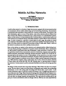
Mobile ad hoc networks (MANETs) are collections of wireless mobile nodes in which nodes communicate with each other without pre-established infrastructures. Because MANETs provide mobile nodes with reliable routing services in the absence of a network infrastructure, they are applied to several popular wireless technologies including cellular phone services, disaster relief, emergency services, battlefield scenarios, and other applications. Furthermore, MANETs are decentralized networks, and the network topology is unpredictably dynamic because of node mobility. As a result, mobile nodes in MANETs act as both hosts and routers since MANETs are decentralized; all mobile nodes need to discover the dynamic topology and deliver messages by themselves. These mobile nodes establish the routing tables by exchanging routing messages with each other and then delivering data packets for others. Therefore, developing a system to maintain routing tables reliably is the most fundamental and critical issue related to MANETs. Optimal Link State Routing (OLSR) is representative of a proactive, link-state routing protocol of MANETs, and the Ad Hoc On Demand Distance Vector (AODV)
2 is the other popular, reactive, request-on-demand routing protocol. Both OLSR and AODV have IETF RFCs and will be introduced in the following chapters. Generally, MANETs rely on the cooperation of all mobile nodes in the network to ensure reliable routing services in the presence of dynamic topology caused by their mobility. The dynamic and cooperative nature of MANETs presents substantial challenges for network security. Therefore, sufficient protection should be provided to secure MANETs to guarantee the integrity of routing messages and availability of routing services. In other words, the goal of this dissertation is to examine how to secure the routing services of MANETs in order to provide reliable communication among nodes.
1.2
Vulnerabilities in MANET
Security is an important issue for MANETs, especially in critical applications, such as in battlefields and in disaster recovery. Unlike wired networks, which have a higher level of security for gateways and routers, ad hoc networks have characteristics such as dynamically changing topology, weak physical protection of nodes, the absence of centralized administration, and high dependence on inherent node cooperation. As the topology keeps changing, these networks do not have a well-defined boundary, and thus, network-based access control mechanisms such as firewalls are not directly applicable. In addition, there is no centralized administration, making bootstrapping of cryptographic systems very difficult. Due to the shared nature of wireless channels, noise within the channels, and instability caused by mobility, wireless communication is much more vulnerable to attacks than wired networks. Dependence on cooperative communication behavior and the presence of highly dynamic network topology make MANETs more vulnerable than normal wireless networks with base stations. In general, a MANET is a trust-all-peers design, which assumes that each node provides accurate routing information and acts as a router
3 to cooperatively forward packets. By exploiting these assumptions, a malicious node can easily corrupt the routing ability of the network by sending incorrect routing messages[37][39]. An attacker can send incorrect routing messages either by initiating corrupt packets or by modifying forwarded packets. It is extremely easy for a malicious node to compromise the entire network. As a result, ad hoc networks are vulnerable to several routing attacks, including address spoofing, modification of packets, black hole, man-in-the-middle, and distributed denial-of-service (DDoS).
1.3
Cryptographic Approaches in Securing MANET
Most research about securing MANET routing protocols use cryptographic approaches based on public key infrastructure (PKI). For example, ARAN[37] and SAODV[42] apply PKI on AODV to generate digital signature to protect the integrity of AODV routing messages. A secure OLSR protocol also uses digital signature to protect OLSR routing messages. Besides AODV and OLSR, PKI is also applied to protect other routing protocols of MANETs. Although cryptographic schemes can protect a forwarded packet from being modified, they have numerous limitations for securing routing protocols. For example, they cannot prevent a node from initiating a packet with forged contents. Furthermore, PKI schemes require high computational overhead, which may consume all the computational resources and result in denial of service attacks. In addition, some of these cryptographic approaches do not cover critical fields, such as hop count, the value of which will change over time. Another limitation is that they cannot prevent insider attacks. Therefore, other mechanisms must be developed to complement the limitations of cryptographic approaches, and this exemplifies is the need for Intrusion Detection to secure MANET routing.
4
1.4
Intrusion Detection
Security services, such as authentication services and access controls, can enhance the security of ad hoc networks. Nevertheless, these preventive mechanisms alone cannot deter all possible attacks, such as insider attackers. Therefore, it is necessary to have other security mechanisms to deal with misbehaving insider nodes that possess valid key and access rights. Intrusion detection, which has been successfully used in wired networks to identify attacks, can provide a second line of defense. In particular, an intrusion detection and response capability is very important, since many real ad hoc networks will be deployed in hostile environments in which legitimate nodes can be captured and used by adversaries. Intrusion detection involves the runtime gathering of data from system operation, and the subsequent analysis of the data; the data can be audit logs generated by an operating system or packets “sniffed” from a network. Intrusion detection techniques can be classified into categories: signature-based detection, anomaly detection, and specification-based detection. In signature-based intrusion detection, the data is matched against known attack characteristics, thus limiting the technique largely to known attacks (even excluding variants of known attacks). In anomaly detection[20], profiles of normal behavior of systems, usually established through automated training, are compared with the actual activity of the system to flag any significant deviation. A training phase in anomaly-based intrusion detection determines characteristics of normal activity; in operation, unknown activity, which is usually statistically and significantly different from what was determined to be normal, is flagged as suspicious. Anomaly detection can detect unknown attacks, but often at the price of a high false alarm rate. In specification-based detection[22][23], the correct behaviors of critical objects are abstracted and crafted as security specifications, which are compared to the actual behavior of the objects. Intrusions, which usually cause an object to behave in an
5 incorrect manner, can be detected without exact knowledge about the nature of the intrusions. Currently, specification-based detection has been applied to privileged programs, applications, and several network protocols. In chapter 2, we illustrate IDS works in MANETs in detail, and we introduce several intrusion detection models adapting the specification based approach for MANETs in the following chapters.
1.5
New challenges of IDS in MANET
Because of unique MANET features and limitations, developing IDS for MANET has many difficult challenges that differ from those in wired networks. First, nodes in MANET are expected to be honest routers that work cooperatively. A malicious node may take advantage of this characteristic to launch many routing attacks. These attacks can be new attacks in MANET and are difficult to detect. A new intrusion detection mechanism must be developed in order to detect these new attacks. Second, since MANET is a fully distributed environment without a centralized point, IDS cannot detect these routing attacks if each distributed detector does not have monitoring information from others. Therefore, IDS needs a practical and scalable architecture to gather sufficient evidence in order to detect the attacks effectively. Third, because of mobility, the network topology in MANETs is highly dynamic, and the changes are unpredictable. Detectors must have sufficient, up-to-date evidence in real-time to detect the attacks with low false positive and negative rates. In addition, wireless links between mobile nodes in MANET are much more unreliable than those in a wired network; therefore, the detection mechanism must be capable of tolerating message loss in order to have sufficient data to analyze and to maintain detection accuracy. Furthermore, mobile nodes in MANET usually have limited bandwidth and computational power. MANET is very sensitive to message overhead generated by IDS. High computation mechanisms, such as the public key
6 system, may cause denial of service attacks and are not suitable for MANET. For performance consideration, the detectors are required to generate low message and computational overhead. Finally, nodes in MANET do not have trust management between them, so that attacks may propagate and paralyze the network quickly. Detectors should automatically terminate the attacks and recover the routing topology in real-time in order to minimize the attack damage in time.
1.6
Contributions
Our proposed Intrusion Detection System (IDS) detects insider attacks on MANET routing protocols, and it is the first complete IDS with several innovative models including two intrusion detection models, a message exchange model, and an authentication model. This effective IDS can overcome the challenges discussed above and adapt to the unique MANET environment with low message and computation overhead. We apply a specification based detection approach to precisely detect routing attacks that violate detection constraints. The constraints define the normal behaviors of the target routing protocol and violations of these constraints are potential routing attacks. The distributed detectors use these constraints to detect corrupt routing messages, causing the violations, and then correct the corrupt message contents to stop the attacks. There are two main categories of routing protocols in MANETs. One is proactive link-state and the other is reactive request-on-demand protocol; OLSR and AODV are two representative routing protocols, respectively. First, we propose two specificationbased intrusion detection models for both of them. Then we propose distributed intrusion detection models to improve the first two models and make them practical and scalable.
7 In chapter 3, we propose our first specification-based intrusion detection model for AODV. AODV has significantly different specifications from OLSR: instead of maintaining routes all the time, AODV establishes routes on demand by flooding routing messages when a node has a packet to send, but no route is available from the source to the destination. Therefore, the detection model of AODV is designed based on tracing the procedure of flooded routing messages. In this model, “previous node” and “session tree” techniques are used to trace the route request and response flow and record the routing data in the flow. If an intermediate node of a route maliciously changes the content of any flooded message, detectors can detect it according to the traced routing data. This model is presented by a detailed detection mechanism and numerous example scenarios. In chapter 4, we develop the first intrusion detection model for OLSR. This model analyzes the vulnerabilities of OLSR and summarizes them as four basic attack methods. Then it analyzes the specification of OLSR and develops four detection constraints to prevent routing attacks using the attack methods. Experimental results and example scenarios show that the model detects routing attacks with no false positives and negatives under the assumption that all routing messages are aggregated at a central point for detection analysis. In addition, the model is formally analyzed to show that the model can detect malicious OLSR routing messages and precisely correct them with detection constraints. In chapter 5, we develop a Distributed Evidence-driven Message Exchange intrusion detection Model for MANET (DEMEM). DEMEM is a scalable distributed intrusion detection model, which is designed to efficiently and effectively detect attacks in real-time. Each node has a detector, and the model only requires that the detector validates the incoming routing messages, instead of constantly monitoring all the traffic. Also, it only requires detectors to exchange messages with their local neighbors (at most 2 hops) such that it can minimize the message and computation
8 overhead. In addition, it can tolerate message loss, which is very common in wireless networks. Thus, it is a scalable, efficient, and effective intrusion detection model because it can overcome challenges, such as decentralized networks and mobility issues in MANETs. Also, in the second part of chapter 4, we implement DEMEM in OLSR with three ID messages, which allow detectors to effectively exchange necessary routing data for detection analysis within 2 hops in order to minimize message overhead. In MANETs, mobility contributes to frequent message loss and our message exchanging mechanism can solve the message loss problem and make the entire IDS more reliable. In addition, DEMEM can tolerate ”temporary inconsistency” during the process of updating new link status (e.g. new link or lost link). Under high mobility and message loss conditions, experimental results show that the model has very low false positives, no false negatives, and low message loss or delay. In conclusion, DEMEM, a scalable architecture for MANET IDS, is the pioneer that can detect routing attacks in MANET effectively and efficiently in real-time with practical assumptions and conditions. In chapter 6, we propose Distributed Routing Evidence Tracing and Authentication intrusion prevention model for MANETs (DRETA). DRETA is a message authentication model with low computational overhead. First, DRETA provides a fundamental IP address authentication service for intrusion detection and can be integrated with all intrusion detection models discussed in this dissertation. Second, DRETA protects the integrity of forwarded routing messages, including mutable values (e.g. hop count and TTL). DRETA utilizes one-way key chain and hash function to produce Message Authentication Code (MAC) to protect message integrity. Because the keys in a key chain are symmetric keys, DRETA has much lower computational overhead than other secure routing protocols (such as those using PKI), and DRETA uses delay key disclosure to achieve the same effect of PKI. Furthermore,
9 DRETA is developed by considering the key management issue, where nodes are required to forward their keys only to their 2-hop neighbors in order to minimize the key distribution overhead. We implement DRETA in AODV, which deeply relies on message forwarding. The implementation makes the specification-based detection model for AODV in chapter 3 practical and scalable. In addition, we also apply DRETA to DEMEM in order to resolve the last critical assumption in DEMEM. Experimental results show that implementation of both AODV and OLSR has low message and computational overhead, no false positives and negatives, and very low delay. Thus, our intrusion detection models are successfully integrated together and precisely resolve expected routing attacks in two representative routing protocols in MANETs, using low overhead and practical assumptions. In chapter 7, we discuss several future works that our proposed IDS does not support. First, this IDS only supports attack recovery by an individual node, and we are developing a new cooperative intrusion response model that aggregates the intrusion responses to be a global response. Second, this IDS can only handle attacks launched by non-correlated attacker. The correlated attacks, such as tunneling attacks, cannot be detected by this IDS. In the future work, we discuss several possible technique to resolve tunneling attack. In addition, we discus applying this IDS to other routing protocols in MANET in the future work.
10
Chapter 2 Related Works 2.1
Introduction
Security services, such as authentication services and access controls, can enhance the security of ad hoc networks. Nevertheless, these preventive mechanisms alone cannot deter all possible attacks, such as insider attackers. Therefore, it is necessary to have other security mechanisms to deal with misbehaving insider nodes that possess valid key and access rights. Intrusion detection, which has been successfully used in wired networks to identify attacks, can provide a second line of defense. The related secure routing works in MANETs can be categorized into three subareas: the works in first category are based on authentication-based approaches directed at the ad-hoc routing protocols. Authentication based approaches are used to secure the integrity and the authenticity of routing messages, such as Authenticated Routing for Ad-Hoc Networks (ARAN)[37], Ariadne[17], and Secure AODV[42]. The works in second category are IDSes targeted at mobile ad hoc networks, including IDS frameworks for MANET, statistical anomaly based IDS for detecting insider attacks, and security analysis for selected protocols. The last category is malicious packet dropping detection. MANET routing services require cooperation among all nodes,
11 so detecting selfish nodes and enforcing cooperative participation are important. In this category, either statistical or reputation-based approaches are used.
2.2
Authentication Approaches
The cryptographic approaches [17][2][42] [37][31][41] propose authentication protocols for the routing control data message exchange in several protocols. Authenticated Routing for Ad-Hoc Networks (ARAN)[37] assumes that every node has its own public and private keys distributed by a trusted sever. The originator sends out a Route Request(RREQ) with its signature, and each intermediate node will verify the signatures of the previous intermediate node and the sender, and generate its packet signature to replace the signature of previous intermediate node. Zapata and Asokan[42] proposed Secure AODV, which uses asymmetric cryptography to secure the AODV routing protocol. Adjih[4] proposed a secure OLSR protocol to prevent replay attacks by using a signed time stamp to verify the freshness of a message. Papadimitratos and Haas proposed a secure link state routing for mobile ad hoc networks[31]. This work protects link state routing information by attaching certified keys to the link state updates which are flooded within a routing area. These works use public key based signatures to protect routing message header from being modified and keep the header readable. However, computation overhead of public key based signatures may not be affordable for mobile nodes in MANET. Adrian Perrig proposed a symmetric key based broadcast authentication protocol, called TESLA (Timed Efficient Stream Loss-tolerant Authentication)[2]. TESLA authenticates broadcast messages by one-way key chain, which are symmetric keys generated by one-way hash function. TESLA also proposed delayed key disclosure and time synchronization protocol to support symmetric keys of one-way key chains achieving asymmetric properties. Besides, Hu proposed Ariadne[17], a secure version
12 of Dynamic Source Routing (DSR), which applied TESLA to reduce computation overhead. These secure routing works have three drawbacks. First, although key cryptography can protect the integrity of forwarded packets, it cannot prevent a node from initiating a new message with incorrect information. Second, most secure protocols (except using TESLA) require heavy computation and key distribution involved in public key cryptography. The signature computation and distribution overheads are very expensive for MANET which consists of distributed mobile nodes with limited power and bandwidth. Finally, some cryptographic schemes require modifications of the target protocols, and thus they are not compatible with original protocols and have difficulties to be employed.
2.3
IDS Approaches in Mobile Ad-hoc Net-works
Typical IDSes in wired networks have one characteristic in common: they have a centralized point that can aggregate all of the traffic for analysis. This centralized IDS structure is not feasible for a fully distributed MANET. To resolve this lack of central authority, distributed cooperative IDSs are proposed for MANETs. Zhang and Lee[43] proposed first integrated IDS architecture in 2000. They presented a cooperative distributed intrusion detection framework for MANET. Their primary approach is anomaly detection, which includes anomalies in routing updates, route requests, service requests, and duration of service requests. In 2003, Huang and Lee[6] presented a cooperative cluster-based architecture primarily designed for statistical anomaly detection. Sterne [11] presented a cooperative intrusion detection architecture developed to address the unique challenges in the MANET domain. Subhadhrabandhu[12] evaluated several selection strategies for placement of IDS modules for misuse detection within mobile ad hoc networks.
13 Ramanujan[34] presented a system to detect, avoid, and recover from malicious attacks. They introduced three key ideas — a distributed firewall mechanism to limit the impact of flooding, an algorithm to detect and recover from attacks causing path failures, and a wireless router extension architecture which allows these techniques to be incorporated into existing wireless routers. Kachirski and Guha[3] described a wireless IDS for ad hoc networks based on mobile agent technology. The system has agents at several levels and aggregates their results at some cluster points that are elected using distributed algorithms. The idea is to distribute the IDS functionality between the nodes to minimize the total IDS related processing time by each node. Some IDS approaches are designed to detect attacks on specific routing protocols. These IDSes monitor routing control messages and look for signs of intrusive behavior. Gwalami[14] employed an IDS approach that is based on a stateful analysis of AODV control packet streams. This approach applies State Transition Analysis Technique (STAT) [19], which is developed to model host and network based intrusions in a wired environment. In the current implementation, a sensor is deployed for a group of nodes, and the sensors do not communicate with each other. Peng Ning and Kun Sun[28] presented an analysis of insider attacks on the AODV protocol. Bhargavan presented an AODV formal specification to detect implementation bugs in AODV. The hierarchy structures mentioned in [43][6][11][34][3][14] are conceptual models that have not been realized yet because the foreseen cost of implementing hierarchy is too high. Some IDSes only work for selected routing protocols, such as AODV, so they may not be able to apply for other protocols in MANETs.
2.4
Packet Dropping Detection
Several IDS approaches are proposed to detect malicious packet dropping for MANETs (including both routing and data packets). [8][9][26][27] use the mechanism
14 of assigning a value to the “reputation” of a node and using this information to weed out misbehaving nodes and use only trusted and verifiably good nodes. Primarily, the intrusive activity is that misbehaving nodes agree to forward packets to neighbors but fail to forward the packets. Passive eavesdropping is employed in monitoring the nodes in these approaches. [7] and [36] are statistics-based and credit-based approaches to address packet dropping problems in MANET respectively. A statistical approach is presented by Rao and Kesidis in [35] using estimated congestion at intermediate nodes to decide if the intermediate node is not forwarding packets at the desired rate because of congestion or because of malicious behavior. It is unclear how statistical anomaly detection will succeed in the MANET wireless domain, since establishing normative profiles will be challenging in the presence of dynamic topologies, noisy and intermittent wireless communications and a lack of concentration points where aggregated traffic can be analyzed.
2.5
Specification based Intrusion Detection Systems
Intrusion detection systems on wired network based have generally employed two models: signature based and anomaly based approaches. A signature-based IDS[19][25] monitors activities on the networks and compares them with known attacks. However, a shortcoming of this approach is that new unknown threats cannot be detected. An anomaly based IDS [6][7][36][43][5] monitors the network traffic and compares it with normal behavior patterns statistically. The issue is that anomaly based approaches yield high false positives for a wired network. If we apply these statistical approaches to MANET, the false positive problem will be worse because of the unpredictable topology changes due to node mobility in MANETs.
15 A new approach, called the specification based approach, is recently presented and is ideal for new environments, such as MANETs. A specification based IDS detects attacks(including known and unknown) according to normal behaviors of protected services, such as routing services in MANETs. To do this, the IDS first analyzes the protected protocol specification, and introduces vulnerabilities of the protocol, including useful descriptions of exploits in the protocol. Second, the IDS provides detection rules to enforce the protocol normal behavior. Since malicious nodes have limited known attack methods to take advantage of protocol vulnerabilities, their attacks will cause the violations of the rules and be detected. Thus, the specification based IDS can achieve much lower false positives and negative than those by an anomaly based IDS. And the specification based IDS can detect new or unknown attacks that a signature based cannot detect. Third, since the specification IDS ensures the protocol normal behavior, the specification IDS has clear security goals and policies and formal analysis can demonstrate them. Therefore, we apply the specification approach to protect the routing services in MANETs. In the following chapters, we introduce two specification intrusion detection models for AODV and OLSR.
16
Chapter 3 A Specification-based Intrusion Detection Model for AODV 3.1
Introduction
This chapter describes the first specification based approach applying on intrusion detection in mobile ad hoc networks. In particular, we employ specification-based techniques to monitor the ad hoc on-demand distance vector (AODV) routing protocol, a widely adopted ad hoc routing protocol. AODV is a reactive and stateless routing protocol that establishes routes only as desired by the source node. AODV is vulnerable to various kinds of attacks [28]. This paper analyzes some of the vulnerabilities, specifically discussing attacks against AODV that manipulate the routing messages. We propose a solution based on the specification-based intrusion detection technique to detect attacks on AODV. Briefly, this approach involves the use of finite state machines for specifying correct AODV routing behavior and distributed network monitors for detecting run-time violation of the specifications. In addition, one additional field in the protocol message is proposed to enable the monitoring. We illustrate that our algorithm, which employs a tree data structure and a node coloring
17 scheme, can effectively detect most of the serious attacks in real time and with minimum overhead. This work is the first effort to apply specification based detection technique to detect attacks in ad hoc network that manipulate routing messages to achieve the attack goal. In this chapter, we present the specification of AODV that describes the valid flow of AODV routing messages. Besides, distributed network monitors are used to monitor whether the nodes conform to the specification. Section 2 gives an overview of vulnerabilities in AODV and present several example attacks to motivate the research. Section 3 describes the specification-based approach to monitoring AODV. In addition, it describes the specifications, the monitoring algorithm, and the architecture of the specification-based IDS. In Section 4, we illustrate how our approach and detect expected kinds of attacks mentioned in section 2. Finally, we summarize the work in section 5.
3.2
Vulnerabilities In AODV
AODV is vulnerable to many different types of attacks[28]. In this section, we examine specific vulnerabilities in AODV that allow subversion of routes. In addition, we provide several attack scenarios that exploit the vulnerabilities to motivate our research.
3.2.1
Overview of AODV
The Ad hoc On-demand Distance Vector (AODV) routing protocol is a reactive and stateless protocol that establishes routes only as desired by a source node using Route Request (RREQ) and Route Reply (RREP) messages. When a node wants to find a route to a destination node, it broadcasts a Route Request (RREQ) message with a unique RREQ ID (RID) to all its neighbors. When a node receives a RREQ message, it updates the sequence number of the source node and sets up reverse routes
18 to the source node in the routing tables. If the node is the destination or the node has a route to the destination that meet the freshness requirement, it unicasts a route reply (RREP) back to the source node. The source node or the intermediate nodes that receive RREP messages will update their forward route to destination in the routing tables. Otherwise, they continue broadcasting the RREQ. If a node receives a RREQ message that has already processed, it discards the RREQ and does not forward it. In AODV, the sequence number (SN) plays a role to indicate the freshness of the routing information and guarantee loop-free routes. Sequence number is increased under only two conditions: when the source node initiates RREQ message and when the destination node replies with a RREP message . A sequence number can be updated only by the source or destination. The hop count (HC) is used to determine the shortest path and it is increased by 1 if a RREQ or RREP message is forwarded each hop. When a link is broken, route error packets (RERR) are propagated to the source node along the reverse route and all intermediate nodes will erase the entry in their routing tables. AODV maintains the connectivity of neighbor nodes by sending hello message periodically. Figure 3.1 illustrates the flow of the RREQ and RREP messages in a scenario wherein a node A wants to find a route to a node D. (Initially, nodes A, B, C and D do not have routes to each other). A broadcasts a RREQ message (a1), which reaches B. B then re-broadcast the request (b1). C recieves the messages and broadcasts the message (c1), which arrives at the destination node D. Last, D unicasts back the RREP message to A. We call these RREQ and RREP packets a request-reply flow. The values of the fields in the routing messages are denoted in Table3.1.
19
Figure 3.1: An AODV Scenario
Table 3.1: Values of RREQ and RREP
3.2.2
Vulnerable Fields in AODV Control Messages
In general, AODV is efficient and scalable in terms of network performance, but it allows attackers to easily advertise falsified route information to redirect routes and to launch various kinds of attacks. In each AODV routing packet, some critical fields such as hop count, sequence numbers of source and destination, IP headers as well as IP addresses of AODV source and destination, and RREQ ID, are essential to correct protocol execution. Any misuse of these fields can cause AODV to malfunction. Table 3.2 denotes several vulnerable fields in AODV routing messages and the possible effects when they are tampered with. An attacker could launch a single (packet) attack consisting of several carefully
20
Table 3.2: Vulnerable Fields in AODV Packets modified fields, or an aggregate attack consisting of multiple attack messages, which cause more damages and last longer than a single attack does. The reader is referred to [28] for a more detailed classification of such attacks (termed atomic and compound attacks) as well as simulations of the impact of such attacks. We will briefly describe some of the attacks below.
3.2.3
Examples of Single Attacks
Forging Sequence Number Sequence numbers indicates the freshness of a route to the associated node. If an attacker sends out an AODV control packet for a victim node with a forged large sequence number, it will change the route to that victim node. For example, in our example AODV scenario (see Figure 3.1), if M sends a RREQ, m1, to C with SN.Src equal to 200 (larger than 100), it will take precedence over b1. The route from C to A will go through M instead of going through B. Node M can then control the route between A and D. As another example, if M sends a RREP to B with SN.Dst equal to 100 (larger than 61), it will take precedence over c2. B will send data through M to D instead of C; M can then control the route between A and D. This attack can
21 be defeated by the protocol when the victim node issues a RREQ or RREP with its sequence number larger than that in the attack packet.
Forging Hop Count The damage caused by forging the hop count field will not last as long as the sequence number forging attacks. However, this attack is harder to detect since it is difficult to know the correct hop count to verify the hop count in the attack packet. For example, if M sends a RREQ to C with HC equal to 0 (pretending to be A), it will take precedence over b1 and again, M can control the route. Or, if M sends a RREP to B with HC equal to 0 (pretending to be D) and other values same as c2, it will take precedence over c2 and M can control the route. This attack will be corrected during normal protocol execution when the victim node issues new RREQ or RREP messages with a higher sequence number. On the other hand, this attack could be very powerful when combined with other attacks to form an aggregate attack as described in the following subsection.
3.2.4
Examples of Aggregated Attacks
The attacker can combine multiple single attacks to perform a more complicated attack or make the attack last longer. Some interesting attacks are described below.
Man in the Middle Attack The attacker could issue a fake RREQ and a RREP to poison other node’s forwarding table to divert route. The attacker could send a RREQ to C, m1, which is the same as b1 but with higher SN.Src equal to 200 (larger than 100) to take precedence over b1, and send a RREP to B, m2, which is the same as c2 but with SN.Dst equal to 100(larger than 61) in order to take precedence over c2. The next hub of the reverse route of C is M instead of B, so D and C will go to A through M. The next
22 hub of the forward route of B is M instead of C so A and B will go to D through M. Then M could forward the diverted packets from B and C. Therefore, the complete route is ABMCD instead of ABCD
Figure 3.2: Man in the Middle Attack
Tunneling Attack Tunneling attack is done by two cooperating malicious nodes that falsely represent the length of available paths by building a tunnel between them. In this way, the malicious nodes can force traffic to route through them.
Figure 3.3: Tunneling Attack
As shown in Figure 3.3, there is no direct link between M1 and M2, but M1 and M2 can pretend to be directly adjacent by tunneling. M1 encapsulates the message and sends it through A, B and C to M2, and falsely claims there is a direct link between M1 and M2. In AODV, when S broadcasts RREQ to A and M1, it will get RREP from A and M1, where their path are S, A, B, C, D and S, M1, M2, D. S will choose S, M1, M2, D but it is actually S, M1, A, B, C, M2, D. M1 and M2 successfully
23 prevent S from choosing the shortest path, S, A, B, C, D. Even a cryptography-based solution, such as ARAN [37], cannot prevent this kind of attack.
3.3
Specification-Based Monitoring of AODV
Specification-based monitoring compares the behavior of objects with their associated security specifications that capture the correct behavior of the objects. The specifications are usually manually crafted based on the security policy, functionalities of the objects, and expected usage. Specification-based detection does not detect intrusions directly - it detects the effect of the intrusions as run-time violation of the specifications instead. As the specifications are concerned with the correct behavior of objects, specification-based detection does not limit itself to detecting just known attacks. The specification-based detection approach has been successfully applied to monitor security-critical programs [23], applications, and protocols[22]. In particular, specifications for the Address Resolution Protocol (ARP) and the Dynamic Host Configuration Protocol (DHCP) have been used to detect attacks that exploit vulnerabilities in these protocols. In general, a specification for a network protocol constrains the messages exchanged by the network nodes. The specifications could restrict the way the messages are exchanged (e.g., an ACK followed by a SYN), the contents of the messages. The specifications could also be derived from some desirable global invariants about the protocol. In applying the specification techniques to monitor AODV, we focus first on the routing messages that are exchanged during the discovery of routes. In particular, we attempt to monitor all the RREQ and RREP messages in a request-reply flow from a source node to a destination node and back to the source. Our specification requires that all nodes send RREQ and RREP messages according to the protocol
24 specifications, and the hop count, RREQ ID, and the sequence numbers be correct. In the following subsections, we describe how to monitor a request-reply flow using distributed network monitors (NMs).
3.3.1
Basic Assumptions
In order to narrow the scope of the problem, we employ the following assumptions: 1. The MAC addresses and IP addresses of all mobile nodes are registered and authenticated with the network monitors. 2. Network monitors are able to cover all nodes and perform all required functionality. 3. Every network monitor are trustworthy and can always communicate securely and reliably. 4. Every node neither drops AODV messages nor jamming wireless channels. Some IDS works in chapter 2 can resolve the last assumption. A new model presented in chapter 6 improves this model and protects AODV message without the rest assumptions.
3.3.2
Run-time Monitoring of Request-Reply Flow
The nature of ad hoc networks prohibits a single centralized IDS monitor to observe all messages in a request-reply flow. Therefore, tracing RREQ and RREP messages in a request-reply flow has to be performed by distributed network monitors (NMs). Figure 3.4 depicts the architecture of a network monitor. Networks monitors passively listen to AODV routing message and detect incorrect RREQ and RREP messages. Messages are grouped based on the request-reply flow to which they belong.
25
Figure 3.4: Architecture of Network Monitor A request-reply flow can be uniquely identified by the RREQ ID, and the source and destination IP addresses. A RREQ or RREP message can map to a request-reply flow based on these fields as shown below. RREQ: AODV source address and RREQ ID. RREP: AODV source and destination address. A network monitor keeps track of the RREQ and RREP message last received by each monitored node and maintains the forwarding table of each monitored node. In addition, as each request-reply flow could have several branches - RREQ is a broadcast message and more than one neighbor could continue broadcasting it - NM maintains a session tree to trace the branches. When NM sees an AODV packet as a current packet, NM searches the session tree to find the previous packet of that packet. If NM cannot find the previous packet to match the current packet in the session tree, it will ask its neighboring NMs to find the previous packet. If one of the neighboring NM answers, NM receives the information of the previous packet and the tree it belongs to. Otherwise, NM will treat it as an active-forge anomaly. After comparing the current and previous packet, NM inserts the current packet into the session tree for the next packet. If it is RREP message, NM will mark the new link as read link. Besides, NM will also update its forwarding table. By tracing the session tree, NM
26 can easily match the current and previous packets to detect an anomaly, especially in RREQ messages. Moreover, NM can detect incorrect hop counts of current RREQ packets according to those of previous RREQ messages. NM can also identify the broken links of corresponding to RERR message. Then it can mark out the broken links and tell its nodes not to use those links in a period of time. NM could even map the node suffering from poor connections and issuing lots of RERR messages. Bandwidth overhead is generated by NMs when it needs to ask its neighboring NMs for the information of the nodes which are out of the range of its radio. This happens when the nodes move out of the range of the NM, or the packet is forwarded to a node that is out of its range.
3.3.3
Finite-state Machine Constraints
Figure 3.5: Normal State Diagram
27 A network monitor employs a finite state machine (FSM) for detecting incorrect RREQ and RREP messages, shown in 3.5. It maintains a FSM for each branch of a request-reply flow. A request flow starts at the Source state. It transmits to the RREQ Forwarding state when a source node broadcasts the first RREQ message (with a new REQ ID). When a forwarded broadcasting RREQ is detected, it stays in the RREQ Forwarding state unless a corresponding RREP is detected. Then if a unicasting RREP is detected, it goes to RREP Forwarding state and stays there until it reaches the source node and the route is set up. If any suspicious fact or anomaly is detected, it goes to the suspicious or alarm states. When a NM compares a new packet with the old corresponding packet, the primary goal of the constraints is to make sure that the AODV header of the forwarded control packet is not modified improperly. If an intermediate node responds to the request, the NM will verify this response from its forwarding table as well as with the constraints in order to make sure that the intermediate node does not lie. In addition, the constraints are used to detect packet drop and spoofing. Figure 3.6 shows the suspicious and alarm states. If either sequence number (SN) or hop count (HC) is not consistent, it goes to the SN/HC Forged Suspicious state and NM will ask neighbor NMs to confirm it (shown as (1)). If none of them disagrees, the request flow goes to the SN/HC Forged Alarm. Otherwise, it goes to the RREQ Forwarding State if it is RREQ, or it goes to the RREP Forwarding State if it is RREP. The Out of Range Suspicious state is in case of a RREP message being lost or dropped. Then NM will ask neighboring NMs to confirm it (shown as (3)). If they agree, it goes to the Drop/Lost Alarm. Otherwise, it goes to RREP Forwarding state. If the IP and MAC address mapping is unknown, it goes to the Spoofing alarm (shown as (2)). Each branch of a request flow is independent and will be treated separately.
28
Figure 3.6: Suspicious and Alarm State Diagram
3.3.4
Matching Current and Previous Messages
To determine the validity of a message sent by node A, a network monitor needs to identify the corresponding incoming message to A. For unicast messages, such as RREP, a NM can map current and previous packets easily by looking their source and destination addresses in the IP headers. However, in broadcast messages, such as RREQ, the destination address will always be the broadcast address (255.255.255.255). To keep track of the RREQ path, we add one more field to AODV, called previous node (PN). This field indicates the node that previously forwarded the RREQ to the current node. For example, in the scenario described in Figure 3.7, the RREQ message broadcasted by A is forwarded from B to C then to D. Given the previous node field, we can identify the intermediate path AB by the RREQ message sent by B and the path
29
Figure 3.7: Example of Previous Node BC by the RREQ message sent by C. The NM knows D responds to this request to C by source and destination address in the IP header of RREP from D. Now, the NM can know that A’s request is forwarded by B, C and responded to by D, and therefore have a complete request path from A to D. Also, the NM can know the response path from D to A by the source and destination addresses of the IP header of the unicast RREP messages. Therefore, the NM can trace the complete request flow from A to D and from D back to A.
The Need for the Previous Node Field When NM hears a RREQ with PN, it is able to update the next hop of the reverse route in the forwarding table regarding to PN in RREQ. Otherwise, NM is not able to detect the following two attacks: 1. A malicious node forwards a RREP to the node that is not the next hop of the reverse route. 2. If a node, M, forwards RREP to node A, but A does not forward it to S, then NM cannot determine if:
30 a. The destination, A, dropped the packet, or b. M made the fake smaller hop count in the RREQ it forwarded and M forwards RREP to A via the reverse route it claimed, but actually A is always out of M’s radio range. In order to achieve this attack, M has to know the network topology near M and claim a shorter reverse route that is actually invalid. In (1), with PN, NM can know the next hop of reverse route and therefore can detect a malicious node forwarding packets to the wrong place. In (2), NM could mark out the link between A and M as a bad link. When S rebroadcasts RREQ, D gets a RREQ from M with PN=A, and it will ignore this RREQ. Without PN, D would not know RREQ sent by M was sent from A or some other nodes. Hence D will either ignore all RREQs from M resulting in false negatives, or accept all of them resulting in false positives.
Figure 3.8: Example Scenario
Functionality of NM NMs passively listen to wireless media to monitor AODV packets. They exchange information through a secure channel, and only when additional information of nodes is needed, for example, when the session path moves across multiple NM’s radio ranges. Moreover, based upon the AODV control messages heard, a NM stores the expected forwarding tables of the nodes within its radio range in order to be able
31 to examine in the future if the nodes are misbehaving. With the low overhead and memory storage, NMs are able to detect system errors and anomalies that could lead to potential (and possibly unknown) attacks in real time with low false positives by employing predefined finite state machine constraints (see below).
3.3.5
Construction and Processing of Session Trees
Procedure 1 below describes the process at each Network Monitor (NM). Each NM listens to the channel and start processing when it hears a message M being sent within its radio range.
Procedure 1: Network Monitoring Procedure: 1. while(true) 2.
wait(untilN M hearsmessageM beingsentintochannel)
3.
if (M acIP U nM atch(M ))
4.
DetectSpoof ing(M )
5.
elseif (M.T ype = RREQ)
6.
AddSessionT ree(M )
7.
elseif (M.T ype = RREP )
8. 9. 10.
P eocessSessionT ree(M ) elseif (M.T ype = RERR) M arkLinkBroken(M )
Detect Spoofing Since each NM has a complete mapping between the Mac address and IP address of every node in the network, a NM can examine M to determine if the Mac-IP address is consistent with the preconfigured data in order to detect the spoofing attack (lines 3, 4).
32 Monitoring RREQ - Building Session Trees Procedure 2: AddSessionTree(M) 1.
RetrieveT ree(M.AODV Src, M.RRID, SessionT reeList, T )
2.
RetriveP revM sg(M.P revN ode, P revM )
3.
CheckConsistency(M, P revM )
4.
AddT reeN ode(M, T )
5.
U pdateF orwardingT able(M, F )
If M is a RREQ, the NM employs AddSessionTree(M) shown in procedure 2. SessionTreeList is the list of trees in which each tree corresponds to each RREQ session. In the RetrieveTree procedure (line 1), AODV source address (AODVSrc) and RREQ ID (RID) in the RREQ are used to identify and retrieve the session tree. If M.IPSrc (Source IP address in IP header of message) is equal to M.AODVSrc (Source IP address in AODV), it indicates that a node has initiated a new RREQ request; so a new session tree will be created. If it cannot retrieve a tree, the NM will request one from its neighboring NMs. If none of them can find a corresponding session tree, an active forged RREQ anomaly is detected. In the RetrivePrevMsg procedure (line 2), the NM searches the RREQ message (PrevM) that is forwarded right before the current RREQ message (M) according to M’s previous node field (M.PrevNode) in the session tree. If the NM and its neighboring NMs fail to find one, it means that the previous node field given in M is incorrect and a fake previous node anomaly is detected. Otherwise, in the CheckConsistency procedure (line 3), the NM verifies values in M such as SN and HC correspond to those in PrevM. Then, the NM trusts the values in M, adds it into the session tree (line 4) and updates the forwarding table (F) (line 5) according to the reverse route given in M.
33 Monitoring RREP Procedure 3: ProcessSessionTree(M) 1.
RetrieveT ree(M.AODV Src, M.AODV Dst, SessionT reeList, T )
2.
if (InitRREP (M, T )andN otDst(M, T ))
3. 4.
V erif yRREP (M, F ) elseif (F orwardedRREP (M, T ))
5.
RetriveP revM sg(M.IP Src, P revM )
6.
CheckConsistency(M, P revM )
7.
AddRREP P ath(M, T )
8.
U pdateF orwardingT able(M, F )
If M is an RREP, the NM processes M in ProcessSessionTree(M), shown in procedure 3. In the RetrieveTree procedure (line 1), the AODV source address (AODVSrc) and AODV destination address (AODVDst) in RREP are used to identify and retrieve the session tree. If the NM and its neighboring NMs fail to get one, an active forged RREP is detected. InitRREP (line 2) is true if a node (M.IPSrc) that is not in the tree replies a RREP to one of the node (M.IPDst) in the tree. NotDst is true if the sender (M.IPSrc) is not the destination of the request (M.AODVDst). The NM will only verify a new RREP generated by an intermediate node according to its forwarding table since NMs trust new RREP issued by the destination of AODV request. ForwardedRREP is true if the sender of the RREP is the tail of RREP path and the destination of the RREP is not in the RREP path but in the session tree. Then the NM retrieves the previous message (PrevM) which is the tail of RREP path and check consistency according to PrevM. Now NM trusts this new RREP, adds it into the RREP path of the tree, and updates the forwarding table (F) according to the forwarding route given in M.
34 In addition, if all RREP paths go back to the source of the request (M.AODVSrc) and no more RREPs are detected, then the whole tree can be discarded. Also, before a complete RREP path to source is established, if no RREP is added in a period of time, the NM will report a drop/loss anomaly.
Monitoring RERR Finally, if M is an RERR, then the NM updates the forwarding table according to which node is unreachable by which node. To prevent an attacker from repeatedly using RERR to perform an attack, a broken link is forced to remain in that state for a finite period of time.
3.4
Examples
In order to show how the IDS detects attacks, we first describe how the network monitors trace AODV packets based on the AODV scenario in Section 3.2.1. Then we show how we detect the single attacks in Section 3.2.3 and aggregated attacks in Section 3.2.4.
3.4.1
Tracing AODV Packets
Figure 3.9: Example AODV Scenario with Network Monitors
In Figure 3.9, two network monitors, N1 and N2, work cooperatively and trace
35 the request flow shown in section 3.2.1. Table 3.3 shows the AODV packets that N1 and N2 see in each time slot. Table 3.4 shows how N1 and N2 build up their session trees step by step according to the AODV packets shown in Table 3.3.
Table 3.3: Packets in NM in Each Time Slot
Table 3.4: Session Trees in NM in Each Time Slot (— : RREQ only; = : RREQ and RREP)
Table 3.5: Entries of N1’s and N2’s forwarding table in each time slot(in parentheses) At time slot 2, N2 sees b1 but did not see the original packet sent from A, so N2 asks its neighboring monitor, N1, to confirm this. Similarly, at time slot 5, N1 sees c2 and asks N2 to retrieve the complete session tree. Table 3.5 shows the forwarding tables of N1 and N2 according to AODV packets they see in each time slot.
36
3.4.2
Detecting Simple Attacks
Detect Attacks by Forged Sequence number According to the forwarding table in N1 and N2, SN.Src is 100 and SN.Dst is 61. If N1 or N2 detect any packet having SN that is larger than it should be and that packet is not sent by the owner of SN (IP.Src not equal to source or destination Node (depending on message being RREQ or RREP)), it will treat it as an attack. Therefore, the attacks shown in section 3.3.3 will be detected.
Detect Attacks by Forged Hop count According to the forwarding table and session tree, if the hop count does not increase by 1 following the session tree, NM will treat it as an attack. Therefore, the attacks shown in section 3.3.3 will be detected.
3.4.3
Detecting Aggregated Attacks
Man in the middle attack Since SN of the packets sent by M is larger than that NMs have and the packets were not sent by the owner of SN, (IP.src not equal to source or destination Node (depending on message being RREQ or RREP)) the NM will detect the attack.
Tunneling attack In this attack, the attack claims that the route is S, M1, M2, D although the real route is S, M1, A, B, C, M2, D. When M2 gets the unicasting RREP which is actually forwarded to C, our IDS would know it by checking its IP header and notice that it is not forwarded by M1 according to the route given by the AODV packets sent by M1 and M2. Therefore, our IDS detects that the link between M1 and M2 is actually fake.
37
3.5
Conclusion
We propose a specification-based intrusion detection system that can detect attacks on the AODV routing protocol. In a specification-based intrusion detection approach, the correct behaviors of critical objects are manually abstracted and crafted as security specifications, and this is compared with the actual behavior of the objects. Intrusions, which usually cause object to behavior in an incorrect manner, can be detected without exact knowledge about them. This approach can, thus, address unknown attacks as well. The IDS presented in this model is built on a distributed network monitor architecture that traces AODV request-reply flows. Network monitors audit every RREQ, RREP and RERR in order to build and update complete request-reply session trees and corresponding forwarding tables. Constraints on the request-reply flow are specified using finite state machines. We describe procedures for constructing and processing the session trees, and present examples of detecting attacks successfully. This research is the first effort to apply specification-based detection techniques to detect attacks in the routing within ad hoc networks. We illustrate that our algorithm can effectively detect most of the serious AODV routing attacks effectively, and with low overhead. In next chapter, we present another specification based IDS for OLSR (OLSR is completely different routing protocol in MANET). Because the IDS in this chapter is based on several strong assumptions, in chapter 6 we introduce a new practical model that has much fewer assumptions and greatly improve the performance and scalability of the IDS in this chapter.
38
Chapter 4 A Specification-based Intrusion Detection Model for OLSR 4.1
Introduction
In this chapter, we introduce a specification based intrusion detection model for detecting attacks on routing protocols in MANETs. Intrusion detection is a viable approach to enhancing the security of existing computers and networks. Briefly, an intrusion detection system monitors activity in a system or network in order to identify ongoing attacks. Intrusion detection techniques can be classified into anomaly detection, signature-based detection, and specification-based detection. In anomaly detection [20], activities that deviate from the normal behavior profiles, usually statistical, are flagged as attacks. Signature-based detection [19][25] matches current activity of a system against a set of attack signatures. Specification-based detection [23] identifies system operations that are different from the correct behavior model. Our specification-based approach analyzes the protocol specification of an ad hoc routing protocol to establish a finite-state-automata (FSA) model that captures the correct behavior of nodes supporting the protocol. Then, we extract constraints on
39 the behavior of nodes from the FSA model. Thus, our approach reduces the intrusion detection problem to monitoring the individual nodes for violation of the constraints. Such monitoring can be performed in a decentralized fashion by cooperative distributed detectors, which allows for scalability. In addition, since the constraints are developed based on the correct behavior, our approach can detect both known and unknown attacks. We choose OLSR(Optimized Link State Routing)[10] as the routing protocol for the current investigation. In particular, we focus on the correctness of the route control traffic generated by nodes. The intrusion detection model consists of four constraints on the control traffic between neighboring nodes, i.e., on the Hello and Topology Control (TC) messages of OLSR that are assumed here to be the only messages used to establish the routing topology in OLSR. We analyze the model and experiment with it in a simulated MANET environment to investigate its detection capability and false positive rate. In Section 2, we provide an overview of OLSR and analyze vulnerabilities related to the Hello and TC message traffic, including a description of possible attacks on OLSR and their impact. In Section 3, we describe the FSA model of OLSR, and discuss the behavioral constraints for detecting attacks. In addition, we discuss temporary inconsistency issues and limitations. In Section 4, we present an analysis of the model illustrating that the constraints can ensure the integrity of the OLSR network. In Section 5, we discuss implementation of the constraints, example attacks, and simulation results of the model in the GlomoSim simulation platform. Finally, in Section 6, we present a brief survey of the related literature, and conclude in Section 7.
40
4.2
OLSR Vulnerability Analysis
In this section, we provide an overview of the OLSR protocol and discuss its vulnerabilities.
4.2.1
Overview of OLSR
OLSR is a proactive table-driven link-state routing protocol developed by INRIA [10]. The protocol is a refinement of traditional link state protocols employed in wired networks; in the latter, the local link state information is disseminated within the network using broadcast techniques. This flooding effect will consume considerable bandwidth if directly employed in the MANET domain, and therefore, OLSR is designed to optimally disseminate the local link state information around the network using a dynamically established sub-network of multipoint relay (MPR) nodes; these are selected from the existing network of nodes in the MANET by the protocol. OLSR employs two main control messages: Hello messages and Topology Control (TC) messages to disseminate link state information. These messages are periodically broadcast in the MANET in order to establish the routing tables at each node independently. In OLSR, only nodes that have bidirectional (symmetric) links between them can be neighbors. Hello messages contain neighbor lists to allow nodes to exchange neighbor information, and set up their 1-hop and 2-hop neighbor lists; these are used to calculate multi-point relay (MPR) sets. An MPR set is a 1-hop neighbor subset of a node to be used to reach all 2-hop neighbors of the node. OLSR uses MPR sets to minimize flooding of the periodic control messages. Nodes use Hello messages to announce their MPR sets together with 1-hop neighbor sets. When a node hears its neighbors choosing it as an MPR node, those neighbors are MPR selectors of the node, and the node will announce its MPR selector set to the network by broadcasting TC messages.
41 TC messages are forwarded by MPR nodes to all nodes of the network. When a node receives a TC message, it will note that the originator of TC message is the ”lasthop” toward all MPR selectors listed in the TC message. The links are then added into the topology table. Using its topology table, the node can set up its routing table by recursively traversing the (last-hop to node, node) pairs in its topology table (see Figure 4.1) and picking up the shortest path with the minimal hop count. Therefore, each node of the network can reach all other nodes.
Figure 4.1: Generation of a route from Topology Table
4.2.2
OLSR Vulnerability and Attacks
Several studies have been done on the vulnerabilities of OLSR [15][4]. In general, an attacker can fabricate packets, intercept and modify packets going through it, or refuse to forward packets, causing compromises of confidentiality, integrity, and availability. In this work, we only focus on those vulnerabilities that could compromise the integrity of the network, i.e., the routing tables in the nodes. In OLSR, each node injects topological information into the network through HELLO messages and TC messages. Therefore, a malicious node can inject invalid HELLO and TC messages to disrupt the network integrity, causing packets to route incorrectly or to the advantage of the attacks. Table 4.1 displays the critical fields in the Hello message and the TC message on which the computation of the routing table depends. The 1-hop neighbor list in a Hello message is used by its neighbor to create the 2-hop neighbor list and MPR set. The MPR set in a Hello Message denotes the MPR set of the sender. The MPR
42
Table 4.1: Critical fields in Hello and TC Messages selectors in TC messages are used in calculating routing tables at nodes receiving the messages. Thus, an attack can: 1. provide an incorrect 1-hop neighbor list in a Hello message 2. provide an incorrect MPR set in a Hello message 3. provide incorrect MPR selectors in a TC message 4. modify the MPR selectors and ANSN before it forwards a TC message An attacker can launch more sophisticated attacks such as denial-of-service or man-in-the-middle attacks by combining the four basic attack methods. We address such correlated attacks in section 4.3.4.
4.2.3
Attack Impact
Since every node concludes the same topology for the network from the TC messages broadcasted around the MANET, an attacker can influence this topology using the four attack methods described above. He can add or delete links in the routing tables of other nodes with these invalid messages. In addition, invalid messages from an attacker may trigger other incorrect messages that invalidate routing tables in the entire MANET. For example, using the first method, an attacker can add a non-neighbor node in the 1-hop neighbor list of its Hello message. Other neighbor nodes of the attacker node may add the attacker as MPR in their Hello messages due to this non-existent
43 neighbor. The attacker can now advertise this in its TC messages. As the TC message propagates through the whole network, every other node’s routing table is corrupted. With regards to the TC message vulnerabilities, examples of attack include the following: If, in an initiated TC message, an attacker node fails to include a legitimate MPR selector, this may potentially deny service to this existent MPR selector; this denial of service may be partial or total depending on the topology around the victim node. Similarly, if, in a forwarded TC message, an attacker modifies the ANSN field, or the MPR selector list, then it effectively alters how the routing table is established at other nodes around the network. This may affect not only the network service at the neighborhood of the victim node that originated the TC, but may result in cascading network effects that arise from how routing decisions are made by nodes around the network. These modifications of OLSR control message fields used by a single attacker as described above follow the basic format specifications of OLSR messages. This makes them hard to detect. However, they conflict with other OLSR control messages from other nodes. We call these conflicts ”inconsistencies”. In the next section, we define constraints to be employed within the proposed intrusion detection model to detect those control message inconsistencies that lead to the possible attacks.
4.3
Intrusion Detection Model
This section describes our specification-based approach to detecting attacks in OLSR. In general, specification-based detection recognizes attacks by comparing the activity of an object with a model of correct behavior of the object. It has been applied to detect attacks on computer programs and network protocols. Specification-based detection is particularly suitable for detecting attacks on network protocols because the correct behavior of a protocol is usually well defined and documented in the
44 protocol specification. The challenge is to extract a suitable model of behavior from the protocol specification that can be checked at runtime using network monitoring. We first list assumptions employed, and then present the correct behavior model of OLSR under these assumptions.
4.3.1
Assumptions
We assume a distributed intrusion detection architecture that allows cooperative detectors to promiscuously monitor all Hello and TC messages, and exchange their local data if necessary. IDS detectors in this architecture can monitor all Hello and TC messages sent by each node of the network, always exchange IDS data successfully, and will not be compromised. In addition, we assume that cryptographic protection, such as DRETA (see chapter 6), is employed to guard against spoofing attacks. Furthermore, we assume OLSR is the only routing protocol in the network and each node has only one network interface. In other words, Multiple Interface Declaration (MID) and Host and Network Association (HNA) messages are not used here. Lastly, we assume nodes forward TC messages following OLSR Default Forwarding Algorithm and nodes forward normal packets to the correct next hop.
4.3.2
Correct Behavior Model of OLSR
Figure 4.2 shows the FSA model of the OLSR protocol that defines the correct operation of an OLSR node in handling control traffic. When a node receives a Hello control message, it will update its neighbor list and MPR set. Upon receiving a TC control message, a node updates the topology and routing table. In addition, the node will forward the TC if it is a MPR node. In addition, a node will periodically broadcast Hello and TC messages.
45
Figure 4.2: OLSR Routing Finite State Automata (FSA) We describe the constraints on the control traffic between neighbor nodes for detecting inconsistencies within the control messages. C1: Neighbor lists in Hello messages must be reciprocal. E.g., if node 2 is the neighbor of node 1, then node 1 must be node 2’s neighbor. C2: The MPR nodes of a node must reach all 2-hop neighbors of the node and the MPR nodes must transmit TC messages periodically. C3: MPR selectors of a TC message must match corresponding MPR sets of Hello messages. E.g., if node 2 is node 1’s MPR selector, node 1 must be node 2’s MPR. C4: Integirty of forwarded TC messages must be maintained. C1 ensures that 1-hop neighbor lists of Hello messages from all nodes are consistent. According to the OLSR routing specification, since 1-hop neighbor lists are consistent, nodes can produce correct 1-hop and 2-hop neighbor lists. C2 ensures that MPR nodes of each node connect all 2-hop neighbors of the node. By definition of MPR, MPR sets are correct. C3 ensures that MPR selector sets are consistent with MPR sets and therefore are correct. C4 ensures that the forwarded MPR selector sets are correct.
46
Figure 4.3: Security Specification Finite State Automata Figure 4.3 (an extension of the FSA in Figure 4.2) depicts the FSA used by the specification-based intrusion detection system. When a OLSR control message violates one of the constraints, the FSA moves from a normal state into one of the alarm states (Modified Hello State, Modified Init TC State, Modified Forward TC State) To recover from the errors, a detector may broadcast the corrected TC message, or force the node causing the violation to resend the corrected Hello message, and thereby recover corrupted routing tables of infected nodes. Thus, the report violation actions in the FSA can be enhanced to perform the corrective action. Since our proposed model is only dealing with intrusion detection, we do not explore such recovery actions further in this work. However, this preliminary recovery model is incorporated into our simulation experiments using GloMoSim, as described in 4.5.
4.3.3
Temporary Inconsistency
Temporary violation of constraints C1, C2 and C3 may occur in a short period of time as links are created or removed when the topology changes. To avoid false alarms, a detector must wait for the two nodes on both sides of a link to learn the
47 new link status before asserting the inconsistency as an attack. For example, if a new link between node A and node B is created, node A may update the status of link A-B and send a Hello message that is not consistent with the previous Hello message of node B, which does not claim that link A-B exists. The detector should wait for node B to receive the new Hello message from A and send a new Hello message that reflects the addition of link A-B. In case of broken links, (leading to lost messages), the detector should wait for the expiration of the old records at the nodes. In other words, if a detector detects violation of constraint 1, 2 or 3 with regard to nodes A and B, and the violation continues to occur after a certain threshold, then the detector will raise an alarm. In addition, because temporary inconsistency propagates due to an unstable asymmetric link, constraints 1 and 2 require 12 seconds and constraint 3 requires 15 seconds because of the 5 second TC interval time. For constraints C4, since the validation of new messages depends on the messages from the originators, temporary inconsistency does not occur.
Figure 4.4: Resolving temporary inconsistency between nodes of a link
Table 4.2: Important Parameters for Temporary Inconsistency
48
4.3.4
Limitations
For a single attack or non-correlated attacks, the model can detect all attacks since we capture all possible ways to modify a single message at a time. But if two or more attackers launch a correlated attack in which incorrect information is supplied to multiple nodes consistently, the constraints may not be able to detect it. For example, if two attackers are not neighbors but both claim they are neighbors, there may be no detectable violation. Because Hello messages are 1-hop broadcast messages and detectors do not know who actually receive them, detectors are not able to employ constraint C1 to detect violations. This attack is a tunneling attack— attackers build up a virtual link between them. We are developing constraints monitoring forwarding behavior in MANETs to allow detection of correlated attacks, such as tunneling attacks, and we will discuss these attacks in chapter 7.
4.4
Analysis of the OLSR Detection Model
In this section, we analyze the OLSR protocol and the proposed detection model to show that the set of constraints C1 — C4 can identify attacks in MANETs. As discussed in section 4.2, a malicious node can disrupt the integrity of the network (causing good nodes to change their routing table to its advantage) by intentionally generating and forwarding incorrect control messages. In particular, we show that in an OLSR network with only one malicious node, these constraints ensure that the malicious node cannot compromise the integrity of the routing tables of any good nodes. Table 4.3 describes the process for establishing the routing table from the perspective of a node. Initially, a node exchanges its 1-hop neighbor list with its neighbors using Hello messages. Then the node establishes its 2-hop neighbor list based on the
49
Table 4.3: OLSR Routing Table Establishment Hello messages from its neighbors. Based on the 2-hop neighbor list, the node generates the MPR set and announces them in Hello messages. Nodes that are chosen to be MPR will generate TC messages and forward TC messages originating from other nodes so that every node will receive all the TC messages. Finally, a node computes the routing table from the information in the Hello messages and TC messages. According to the OLSR protocol RFC [10], each node maintains a link set and a topology set that are used for calculation of the routing table.
The link set
contains the link information of its 1-hop neighbor, and is constructed from the Hello messages it receives. The topology set contains topology tuples in the form of T[DestAddr], T[LastHopAddr], T[Seq], T[HoldingTime], which indicate that one can reach T[DestAddr] through T[LastHopAddr]. The topology set is constructed from the TC messages a node receives. A node computes the routing table from its link set and topology set. Therefore, the routing table of a node is correct if its link set and topology set are correct. Lemma 1: Under assumptions in 4.3.1, all good nodes will have a correct link set if constraint C1 holds. First, according to the OLSR routing specification, a node builds and maintains
50 its link set from the 1-hop neighbor field of the Hello messages it receives. Therefore, if the 1-hop neighbor fields of all Hello messages and the source address are correct, then all nodes will have a correct link set. Now, we show that a Hello message with an incorrect 1-hop neighbor field will be detected as a violation of C1. Consider a bad node which produces a Hello message with an incorrect 1-hop neighbor field. There are two possibilities: 1) It claims another node A as its 1-hop neighbor, but A is not. In this case, the IDS will detect this when it compares the Hello message from the bad node with the Hello message from A. 2) It omits, in its set of 1-hop neighbors, a real neighbor B. In this case, the IDS will detect a violation of C1 when it compares the Hello message from the bad node to the Hello message from B. In both cases, the incorrect Hello message will be detected as a violation of constraint C1. Given that the source address of a Hello message is correct (by the assumption of no spoofing), all nodes will have a correct link set if constraint C1 holds. Lemma 2: The MPR selector field of a TC message generated by an MPR node must be correct if constraint C3 holds. According to the OLSR specifications, a (complete) TC message contains the set of MPR selectors of the originating node. There are two cases in which the MPR selector field in the TC message could be wrong. 1) The MPR selector field contains a node X that is not a MPR selector of M. 2) The MPR selector field misses a node Y that is a MPR selector of M In case 1, the Hello message generated by node X will be inconsistent with the TC message. Therefore, the IDS will detect the violation of constraint C3. In case 2, the Hello message generated by node Y will be inconsistent with the TC message, and thus will be detected.
51 Lemma 3: The MPR selector fields of all TC messages must be correct if constraints C3 and C4 hold. Any TC message in the network is either an original message sent by the originating node or a forwarded message. In the former case, Lemma 1 guarantees the correctness of the selector fields. In the latter case, constraint C4 assure that the forwarded TC message must be the same as the original TC message; thus, the MPR selector field must be correct. Lemma 4: For a node x, which is a n-hop neighbor of a different node y, x will receive TC messages of y with n-1 forwarding if C2 holds. We use induction to prove this lemma. 1) For n = 1, all y’s one-hop neighbors will receive TC messages without forwarding. For n = 2, all y 0 s two hop neighbors will receive TC messages of y with one forwarding if C2 hold. 2) (Induction step) We assume that any node A will receive a TC message of an nhop neighbor B with n − 1 forwarding if C2 holds for all 2 < n < k. For a node x that is a k-hop neighbor of a node y, without loss of generality, let x, N1 , N2 , ..., Nk−1 , y be a path from x to y such that N1 is a MPR of N2 . We argue that such a path exist if C2 holds — since N2 is a 2-hop neighbor of x, there must be a MPR of N2 through which N2 can reach x. As node N1 is a k − 2 hop neighbor of y, by the inductive assumption N1 will receive TC messages from y with k − 2 forwarding. Therefore, x will receive TC messages from y through N1 k − 1 forwarding. By induction, Lemma 4 is true for all integer n > 0. Theorem 1: All nodes will have a correct routing table if constraints C1, C2, C3, and C4 hold. Since each node in the MANET computes the routing table based on the link set and the topology set, the routing table will be correct if the two sets are correct. Given that C1 holds, Lemma 1 ensures that the link set in each node is correct. Given
52 that C3 and C4 hold, Lemma 3 ensures that the MPR selector field of all the TC messages that a node receives is correct. Given C2, Lemma 4 ensures that a node will receive TC messages from all nodes. According to the OLSR specification, the topology set is computed from the TC messages. Therefore, the topology set will be correct if, in addition, every MPR sends out the TC messages. Since constraint C2 guarantees that all nodes in the true MPR set send out TC messages, the topology set in each node must be correct. Therefore, the routing table in each node must be correct.
4.5
Simulation
To measure and validate the effectiveness of our approach, we have implemented the detection mechanism for checking the constraints and experimented with it in a simulated OLSR network under a variety of mobility scenarios. We have implemented several of the example attacks described in Section 4.2 to test the detection capability. In addition, we tested the prototype under a normal situation to measure the performance, especially false positive characteristics.
4.5.1
Simulation Environment
We used the GloMoSim simulation platform to experimentally validate our approach. The simulation is based on IEEE 802.11 and Ground Reflection (Two-Ray) Model, having both the direct path and a ground reflected propagation path between transmitter and receiver. The radio range is around 376.7 meters, calculated by the parameters shown in Table 4.4 [29]. The network field is 1000 m x 1000 m region divided into cells. Nodes are placed into each cell randomly. Each attack scenarios has a stable topology with 10 nodes. Total simulation time is 600 seconds.
53
Table 4.4: Radio Propagation Parameters in GloMoSim In the experiments all mobile nodes follow the Random Waypoint Mobility Model with speed of 5,10, and 20 m/s, and pause times of 0, 30, and 60, ..., 300 seconds. For background traffic, the numbers of mobile nodes uses were 50, 100, 200, and 400. In the experiments, 10% of mobile nodes continuously generated 1024 byte packets at a constant rate of 1 packet per second, 8K bps, across the network topology. The simulation metrics mainly focus on false positives, false negatives, the distribution of temporary inconsistency lasting time and maximum value for each constraint.
4.5.2
Implementation of Detection mechanism
Our proof-of-concept prototype is implemented as a global detector that can monitor all Hello and TC messages in the simulated OLSR network. It is important to note that although the current prototype is a centralized detector, the proposed intrusion detection model can be implemented in a decentralized fashion (See the ongoing work section). As the goal of the proof-of-concept prototype is to validate the detection model, a centralized implementation suffices for validating the false positive and false negative characteristics under our assumptions. Four data tables are maintained by the global detector to record 1-hop neighbors, 2-hop neighbors, MPR and MPR selector sets of all nodes. Four constraints are evaluated according to data tables and incoming messages. An alert will be raised if a constraint is violated. However, topology changes will cause temporal inconsistency
54 and lead to false alert. To minimize the false positive rate, we develop a mechanism to detect temporal inconsistency between new message and old history data. First, we set threshold time for each constraint according to intervals of Hello messages and TC message. Then we generate alerts only when an inconsistency last beyond the threshold time of a constraint. As an example, we list the pseudo code of Constraint C1 in Figure 4.5:
Figure 4.5: Pseudo code of constraint C1
4.5.3
Example Attack Scenario and Results
Figure 4.6: Example Topology in OLSR
We implemented one example of a man-in-the-middle attack and two examples of
55 denial of service attacks using the four attack methods presented in section 4.2.2. We present an example topology, shown in Figure 4.6 and Table 4.5, in order to illustrate the details of the example attacks and their impact.
Table 4.5: Relevant OLSR data for example topology
In each example attack, the attacker uses attack mechanisms slightly modifying the control messages to trigger changes in the routing tables of other nodes as desired by the attacker. These example attacks demonstrate that, by employing carefully designed modifications, an attacker can successfully manipulate routing tables at other nodes. Note that we simulate the attacks with no mobility to ensure the attacks are effective. For each example attack, the detector detects the attacks as violations of the constraints. In this implementation, we combine a recovery model with the intrusion detection model. To recover the corrupted routing tables of infected nodes from the attack, the detector may send the correct TC message with a higher ANSN and the correct MPR selector set to override the corrupted TC message. If the compromised node is the originator of the message, the detector commands the node to resend correct messages to override the corrupted messages. The simulation shows the correct messages successfully override the corrupted messages and correct the infected routing tables.
56
Figure 4.7: Man in the Middle Attack by A1&A3 Man in the Middle Attack by A1&A3 An attacker at node 1 intends to change a route, 8 → 9 → 5 → 7 → 3, to go through itself. It uses attack methods 1 and 3 (see section 4.2.2) to convince nodes 8 and 4 to forward packets toward 3 through itself, and then it can use 2 to forward the packets from 8 to 3. First, by attack method 3, node 1 adds 3 into its MPR selectors in its new TC message to make 8 choose 4 as the next hop toward 3. 8 receives the new forged message and choose 1 as the last hop to 3 in its topology table; this is used to reach all node in 3 or more hops away. Since 1 is a 2-hop neighbor of 8, from 8’s point of view, route 8 → 3 becomes 8 → 4 → 1 → 3, so 8 chooses 4 as the next hop toward 3 in its routing table. Second, by attack method 1, node 1 adds 3 to its 1-hop neighbors in its new Hello message in order to make 4 choose 1 as the next hop toward 3. After receiving the forged message, 4 adds 3 into its 2-hop neighbor list, and chooses 1 as the next hop toward 3 in its routing table. Thus, when 8 forwards packets toward 3 to 4, 4 forwards them to 1, and attacker 1 can forward the packets from 4 to node 2 in order to successfully change the route from 8 to 3. Since 2 received 7’s Hello first and added
57 3 as a 2-hop neighbor, 2 will not choose node 1 as its next hop toward 3. 2 forwards the packets to 7 and 7 forwards them to 3. The attack is a success. Note that attacker 1 has to continuously broadcast forged messages to make the attack remain effective. If an attacker arbitrarily adds other non-neighbors into its 1-hop or MPR selectors, it will easily make itself a black hole. This will attract much useless traffic, marking itself as an attacker. However, in this case, the attacker (node 1) successfully launches a man in the middle attack by slightly changing its two messages without forging its own address, and therefore it is difficult to detect this attack using other existing approaches. Using constraint 3, the detector detects that 1’s MPR selectors = [2,3,4,5] in 1’s TC message do not match 3’s MPR= [7] in 3’s Hello message. Additionally using constraint 1, 1’s 1-hop neighbors = [0,2,3,4,5] in 1’s Hello message do not match 3’s 1hop neighbors = [7] in 3’s Hello message. Since the attacker keeps sending the forged messages, the detected inconsistencies easily last over the temporary inconsistency threshold for C1 and C3, which is 12 seconds. Therefore, the detector detects the attacks correctly. The maximum temporary inconsistency here is less than 12 seconds. Finally, the detector commands node 1 to send correct TC(1) = [2,4,5] and Hello(1) = [0,2,4,5], and then 8 and 4 receive 1’s correct TC and Hello and use 9 and 5 to reach 3. The route is 8 → 9 → 5 → 7 → 3 is recovered.
Denial of Service by A2 An attacker at node 7 intends to annul a route 8 → 4 → 5 → 7 → 3 by attack method 2, i.e., declaring an incorrect MPR list in its Hello message. First, 7 removes 5 from its MPR set(becoming empty) in its Hello message. Second, 5 receives 7’s modified Hello and believes 5 is not in 7’s MPR set, so 5 removes 7 in its MPR selectors = [1,4,6,9] in 5’s new TC. When 8 receives 5’s new TC, 8 believes 8 cannot use 5 as the last hop to reach 7. Since 7 is 3 hops away from 8 and 8 cannot use any
58
Figure 4.8: Denial of Service by A2 other node as the last hop to reach 7, 8 cannot reach 7 and therefore cannot reach 3. The route 8 to 3 is down. This attack is harder to detect than the first one because it requires 2-hop neighbor information which is not explicitly sent out in Hello or TC messages. Note that 5 will not forward 7’s TC messages, so no node except 7’s 1-hop neighbor will have 7’s TC messages. This makes 0, the other 3 hop neighbor of 7, unable to connect to 7. If there were a route from 0 to 3, it is also down. Using constraint 2, the detector detects that 7’s MPR set is empty and 7’s MPR set has not reached all of 7’s 2-hop neighbors [1,4,9]. Once the inconsistency lasts over 12 seconds, the alert is raised. So the detector commands 7 to send correct a MPR set [5] in 7’s new Hello message. When receiving correct Hello message from 7, 5 adds 7 back to 5’s MPR selectors [1,4,6,7,9] in 5’s new TC. Then 8 receives 5’s new TC and uses 5 to connect to 7. The route becomes available again. Here there is no temporary inconsistency for C2, so no false positive.
59
Figure 4.9: Denial of Service by A4 Denial of Service by A4 An attacker at node 2 intends to annul route 8 ↔ 4 ↔ 5 ↔ 7 ↔ 3 by attack method 4, where forwarded TC messages are modified with a high ANSN. It uses two forged forwarded TC messages to remove the global links, 4 → 8 and 7 → 3. First, 2 broadcasts TC(7)=[2,5,6] without 3 to make 8 not use 7 to reach 3; thus route 8 → 3 is down. Again, 2 broadcasts TC(4), which is [1,5], without 8 to make 3 unable to use 4 to reach 8; now route 3 → 8 is down. Since the forged TC messages have high ANSN, all other nodes hearing them replace the correct information with the forged one, so that 8 and 3 cannot communicate with each other. The bidirectional route is down. Note that other nodes except 3,4,7,8 can do the same thing. If 4 or 7 does this, it is using attack method 3, not 4.(see section 4.2.2) This attack can be detected by authenticating forwarding messages, and we discuss it in chapter 6. By constraint 4, the detector detects that TC(4) and TC(7) sent by 2 do not match those from the originators, 4 and 7, respectively. The detector sends correct TC(4) and TC(7) with ANSNs higher than forged messages to override them. Finally, 3 and 8 receive correct TC messages, and are able to communicate with each other. The
60 route is recovered. Here C4 does not require considering any temporary inconsistency thresholds, and there are no false positives and false negatives.
4.5.4
Temporary Inconsistency against Mobility
With no mobility, temporary inconsistencies only happen when nodes establish 1-hop neighbor relationships in the first 5 seconds. Once they are capable of sending TC messages, no temporary inconsistency occurs. In mobile topologies, temporary inconsistencies keep happening while nodes move. We choose different mobility pause times of 0, 30, 60, 120, 300, and 600 seconds employing the Random Waypoint Mobility Model with a speed range of 1 to 20 meter/sec to demonstrate different levels of mobility. We also simulate 10, 20, and 30 traffic sources with continuously generating 512 byte packets at a constant rate of 1 packet per second, 5K bps, across the network topology.
Figure 4.10: Number of lasting temporary inconsistencies with different number of nodes and sources Most temporary inconsistencies will be resolved by the next message of the same kind sent from the same originator and only few of the inconsistencies may last. Figure 4.10 shows the number of lasting temporary inconsistencies caused by mobility. In Figure 4.10(a), 100 nodes in a 2000m x 2000m area result in many more incon-
61 sistencies than 50 nodes in a 1000m x 1000m area. Although 100 nodes generate 2 times the number of messages than 50 nodes, 100 nodes roughly generate 4 times the number of temporary inconsistencies. The higher the degree of mobility is, the more inconsistencies are generated, especially for inconsistency against C1. Figure 4.10(b) shows the number of temporary inconsistencies against C1 in a 50 node topology with 10, 20, and 30 traffic sources. With higher traffic load, the inconsistencies occur more. However, the impact of traffic load for temporary inconsistencies is not as much as that of number of nodes. Therefore, the number of nodes and their degree of mobility are the two main factors of temporary inconsistency.
Figure 4.11: Maximum and Average Temporary inconsistencies lasting time
Maximum temporary inconsistency lasting time indicates what the alert threshold for constraints should be. In Figure 4.11(a), the maximum lasting times of C1, C2 and C3 are less than the thresholds 12 seconds and 15 seconds, and do not lead to false alarms. If the thresholds are 6 seconds, there will be less than 15 false alarms in a 100 node-topology with low pause times. Although the maximum temporary inconsistency lasting time in a 100-node topology is greater than in a 50 node- topology, their average lasting time is roughly the same, where the times of C1 and C2 are about 1.5 to 1.8 seconds, and those of C3 are 4.7 to 4.3 seconds.
62 Also, attacks using the four attack methods are tested in 100 node and 50 node mobile topologies. These attacks consist of arbitrary modified values of 1-hop neighbors, MPR, and MPR selectors in the Hello and TC messages and they will continuously send modified messages at least 1 minute. If the attacks contain the addresses of inactive nodes, which do not send Hello messages for 1 minute and include unused nodes, or the attacks violate C4, the detector raises alarms immediately. If the attacks violate C1, C2 or C3, the detector raises an alert while the attacks last larger than the thresholds. The detector detects all attacks in which the modified messages are sent by the attackers. No false positives are found in a mobile topology with background traffic (20 sources).
4.6
Conclusion
Analyzing the OLSR routing specification, we define the normal OLSR routing behavior and list possible attack mechanisms from a single attacker. Based on the normal routing behavior, nodes retrieve routing information, and establish and maintain their routing tables correctly using the Hello and TC messages. We develop constraints on these Hello and TC messages in order to establish that the integrity of the routing tables at all nodes is not compromised. We develop the proof of satisfaction of the requirement that the integrity of routing tables of all nodes is safe-guarded. Besides, we implement the constraints and example attacks on the Glomosim simulation platform. The following two chapters, we present two models that can resolve two critical assumptions in this chapter. First, in this chapter we assume that it has all Hello and TC messages to have sufficient data for intrusion detection, the next chapter we present a distributed intrusion detection model that can supply sufficient routing data for the detection. Second, in this chapter we assume that a cryptographic protection
63 detects spoofing attacks. In chapter 6 we present a authentication model to prevent address spoofing.
64
Chapter 5 DEMEM: Distributed Evidence-driven Message Exchange intrusion detection Model for MANET 5.1
Introduction
In this chapter, we make two major contributions for intrusion detection systems (IDS) in MANET. First, we propose a practical and effective message exchange model: Distributed Evidence-driven Message Exchanging intrusion detection Model (DEMEM) for MANET. DEMEM overcomes the challenges to distributed IDS architecture of MANET(as discribe in chapter 3 and 4), where detectors do not have sufficient data to detect routing attacks. Instead of adopting costly promiscuous monitoring, detectors in DEMEM simply intercept routing messages and validate these routing messages in order to detect routing attacks. Also, DEMEM segregates the duties of security agents and routing services to avoid modifying the routing proto-
65 cols. The efficient evidence-driven message exchange mechanism provides sufficient evidence in order to perform scalable distributed intrusion detection at each node. Second, we integrate DEMEM into a proactive routing protocol in MANET, Optimal Link State Routing (OLSR) [10] with four practical assumptions, and three new proposed ID messages specifically for OLSR. DEMEM in OLSR uses detection constraints discuessed in chapter 4 [39]. The detection model shows that by validating consistency among related routing messages according to these detection constraints, detectors can precisely detect both known and unknown routing attacks in OLSR. We observe that if detectors within two hops can exchange their routing information, they will have sufficient evidence for detecting violations of constraints. So we propose three ID messages for DEMEM in OLSR to provide the essential ID message exchange service, which is the essential assumptions of previous detection models in chapter 3 and 4. ID-Evidence messages guarantee each detector has sufficient evidence for detecting violations of constraints; ID-Forward messages trigger the selected forwarders sending ID-Evidence messages while the detector observes new evidence in order to minimize message overhead, and ID-Request handles message loss. Thus, DEMEM not only performs practical, scalable, and accurate intrusion detection in OLSR but also tolerates message loss with low message overhead. In addition, DEMEM is capable of being applied to other routing protocols in MANET, such as the other famous proactive protocol, Topology Dissemination Based on Reverse-Path Forwarding(TBRPF)[30], and two popular re-active protocols, Ad Hoc On Demand Distance Vector (AODV)[32] and Dynamic Source Routing(DSR)[21], with different ID messages tailored for different protocols specifically. The remainder of this chapter is organized as follows. Section 2 discusses threats in MANET and the challenges of developing IDS for MANET, especially the lack of an efficient message exchange framework among detectors. Section 3 presents the design of our proposed message exchange framework, DEMEM. Section 4 implements
66 DEMEM in OLSR, a proactive protocol in MANET, Section 5 demonstrates how DEMEM detects OLSR routing attacks through an example scenario and experimental results of DEMEM in OLSR using a simulation. Section 6 concludes the work.
5.2 5.2.1
Threats and Challenges of MANET Threats of MANET
Several studies have been done on the vulnerabilities of MANET protocols [39][33][37]. There are two kinds of packets transmitted in a MANET: routing packets, which are used for maintaining routes, and data packets, which are the actual data communicated between source and destination. In general, a MANET has many intrinsic properties that make it more vulnerable to attacks than wired networks. First of all, every node in a MANET functions as a router that is responsible for routing and packet delivery. If a node is compromised and exploits the cooperation among mobile nodes, the whole network will result in disasters, including incorrect routing topology and delivery failures. Second, all nodes in a MANET share public channels in which attackers can easily target any victim node without passing through physical protection lines at gateways. Third, the topology of a MANET is dynamic and unpredictable due to mobility. Finally, a MANET is a fully distributed environment that lacks an authorized central point to validate message correctness. Because of the last two characteristics, a malicious node can send incorrect routing information to its surrounding nodes to cause routing failures without being noticed by others. In designing protocols, assuming that every node will send correct messages and that every node is cooperating to forward correct messages makes a MANET susceptible to attacks. It is obvious that a corrupt node can easily exploit these assumptions to break the cooperation of all nodes.
67
5.2.2
Attack Model
Routing and data delivery are two fundamental services in MANET. Attackers can easily disrupt the routing topology by manipulating routing packets to cause delivery failures of data packets. Based on the fundamental characteristics of attack packets, we analyze these attacks in three categories:
Forge initiated routing packets Attackers can disrupt routing tables by initiating forged routing packets that are then broadcast to networks. The contents of the initiated routing packets are usually the fundamental bases (for example, 1-hop neighbor information) to build up routing topology. Unfortunately, forge routing data in the initiated packets will propagate through flooding and thus lead to routing failures due to a corrupted routing topology. It is challenging to detect initiated routing packets with forged data because these forged packets follow the specification of routing protocols and thus do not differ from good packets. Cryptographic techniques that are used to authenticate the originators cannot detect initiated packets with forge contents because the attacker is the originator who signed the forge packets with legal keys. This type of attack uses atomic attack methods and can be manipulated by an attacker to launch much more powerful compound attacks. DEMEM provides IDS capabilities to detect this type of attack precisely.
Forge forwarded routing packets as well as node identity Attackers can also disrupt the integrity of forwarded routing packets by modifying the contents of packets passing through them. The attacker can also pretend that he has received some packets from others and then initiating a non-existent forwarded packet. Detection of this category of attacks is relatively easy, since the contents of forwarded packets must remain the same; cryptographic techniques can be used
68 to protect the integrity of the forwarded packets as well as the node identity of all routing packets. Many secure routing protocols and cryptographic techniques have been developed to prevent this type of attack. However, most of them utilize RSA related algorithms, which require high computational overhead and may cause denial of service attacks. Our work in chapter 6, DRETA, is built on a one-way key chain technique using a symmetric key with much less computational overhead. DRETA authenticates the content of forwarded routing packets and node identity to prevent this type of attack, and DEMEM does not cover this kind of attacks.
Drop forwarded packets A selfish node may drop packets routed through it. Unlike the previous two types of attacks, which may cause routing disaster due to a single attacker, this kind of attack is relatively simple and less severe. If a selfish node drops a broadcast routing packet, the dropped packet may reach every node because of the flooding nature. Besides, a data packet drop can be detected if the sender does not receive an acknowledgement from the recipient in a reasonable time period. Several reputationbased works have been proposed to prevent a node from dropping packets[7][36].
5.2.3
Challenges vs. Requirements of IDS for MANET
Because of unique MANET features and limitations, developing an IDS for MANET has many difficult challenges that differ from those in wired networks. First, nodes in MANET are expected to be honest routers that work cooperatively. A malicious node may take advantage of this characteristic to launch various routing attacks. These attacks, shown in the attack model, can be new attacks in MANET and are difficult to detect. A new intrusion detection mechanism must be developed in order to detect these new attacks. Second, since a MANET is a fully distributed environment without a centralized
69
Figure 5.1: Challenges vs. Requirements of IDS in MANET point, IDS cannot detect these routing attacks if each distributed detector does not have monitoring information from others. Therefore, IDSes need a practical and scalable architecture to gather sufficient evidence in order to detect the attacks effectively. Third, because of mobility, the network topology in MANETs is highly dynamic, and the changes are unpredictable. Detectors must have sufficient, up-to-date evidence in real time to detect the attacks with low false positive and negative rates. In addition, wireless links between mobile nodes in MANETs are much more unreliable than those in a wired network, so the detection mechanism must be capable of tolerating message loss in order to have sufficient data in time and to maintain detection accuracy. Furthermore, mobile nodes in MANETs usually have limited bandwidth and computation power. MANETs are very sensitive to message overhead generated by IDSes. High computation mechanisms, such as the public key system, may cause denial of service attacks and are not suitable for MANETs. For performance considerations, the detectors are required to generate low message and computation overhead. Finally, nodes in MANETs do not have trust management between them, such that attacks may propagate and paralyze the network quickly. Detectors should
70 automatically terminate the attacks and recover the routing topology in real time in order to minimize the attack damage in time. Figure 5.1 shows essential requirements for satisfying these unique challenges of MANET.
5.3
Distributed Evidence-driven Message Exchange intrusion detection Model
DEMEM is a solid, scalable, and low message exchange overhead intrusion detection model for MANET. DEMEM overcomes the challenges mentioned in section 5.2.3 through the following three main features: a distributed architecture, an intrusion detection layer, and an evidence-driven message exchange technique.
5.3.1
Distributed IDS Architecture
Figure 5.2: Distributed detectors and Intrusion Detection layer in DEMEM
DEMEM adapts to the distributed and cooperative nature of MANETs. In DEMEM, each node acts as a detector to monitor its 1-hop neighbors by validating routing messages that it receives for intrusion detection purposes. In other words, when
71 a node sends a routing message, all of its neighbors validate the correctness of this message. As seen in Figure 5.2, node A acts as a detector to monitor nodes B, C, and S while nodes B, C, and S are also detectors that monitor node A’s activities. In addition to monitoring activities between 1-hop neighbors, 2-hop neighbors may have to exchange their observed information by tailored Intrusion Detection (ID) Messages to gather enough evidence for detection purposes. Obviously, different MANET routing protocols require different ID messages and exchange these ID messages differently. This approach eliminates complicated topology maintenance and expensive unreliable promiscuous monitoring required by hierarchical cooperative intrusion detection [43].
5.3.2
Intrusion Detection Layer
Much work has been done on secured routing protocols in MANET [37][42][41][4] by modifying existing protocols. However, it takes a long time for these modified protocols to become mature in order to be accepted as standards by authorized organizations, such as the IETF. Therefore, we propose an Intrusion Detection (ID) Layer concept that does not depend on any changes to the protocols but achieves security goals. As seen in Figure 5.2, the detector acts as an Intrusion Detection layer between the routing protocol and the IP layer within a node. The detector intercepts all incoming and outgoing routing messages from the IP layer and to the IP layer. Although DEMEM have new proposed ID messages, the ID layer handles these ID messages so that the routing layer is unaware of their existence. Therefore, DEMEM does not require changing routing protocols but achieves the same protection as other secured protocols. In addition, DEMEM also integrates DRETA (see chapter 6) residing in the authentication layer between the IP layer and the ID layer. The authentication layer has two major tasks. First, the layer signs the sender’s address in outgoing messages. If the node is the message originator and the message will be forwarded by its
72 neighbors, then the layer signs the whole message to protect message integrity. Second, while receiving incoming messages (including ID messages) from neighbors, the authentication layer authenticates the sender’s address. If the sender is not the originator, the layer authenticates the whole message to ensure message integrity. Thus, the authentication layer protects the integrity of forwarded messages and prevents impersonation.
5.3.3
Evidence-Driven Message Exchange
A main contribution of DEMEM is that it adds ID messages to assist intrusion detection. Sending ID messages effectively and efficiently among detectors is very critical, because message overhead introduced by ID messages must be low in a resource-limited MANET. In order to minimize ID message overhead, we propose an evidence-driven approach that has better performance than the periodic-update approach. Evidence is the critical message content of the protecting protocol required to validate the correctness of protocol messages. For example, in OLSR, evidence is the 1-hop neighbor, Multi-Point Relay (MPR) and MPR selector. In AODV, evidence is the sequence number and hop count. New Evidence means any update between the current and the old evidence observed by a detector. For example, assume that node A’s 1-hop neighbor list is B, C at time t1. At time t2, node A’s neighbor list becomes B, C, D so that node A’s new evidence at time t2 is D. So sending New Evidence guarantees each detector’s Evidence is up-to-date. In DEMEM, detectors send ID messages only when they observe or require new Evidence. Figure 5.3 illustrates how this event-driven message exchange task works with the detection task. DEMEM consists of five components, called ID Managers, that are present at every node. In the beginning, the Monitor manager intercepts incoming and outgoing routing messages and handles ID messages. The Evidence manager records
73
Figure 5.3: DEMEM Finite State Machine (FSM) within a detector Evidence in the routing and ID messages. When the Evidence manager observes New Evidence from outgoing routing messages, the Forwarding manager sends ID messages to trigger or to deliver this observed New Evidence to nodes who require it. After receiving an incoming routing message, the Evidence manager will pass this incoming message and the related Evidence to the Validation manager to validate the message’s correctness by the security policies. Once the Validation manager detects violations of security policies, the Response manager analyzes the violations and performs proper attack recovery. Finally, the task goes back to the Monitor manager for the next message. We have implemented DEMEM in OLSR as described in sections 4 and 5. Discussion on applying DEMEM to two popular reactive protocols, AODV and DSR, and to another famous proactive protocol, TBRPF, is presented in future works in chapter 7.
74
5.4 5.4.1
DEMEM in OLSR Routing Attack Methods in OLSR
OLSR is a link-state, proactive routing protocol for MANET. OLSR utilizes periodical Hello and Topology Control (TC) messages to establish a complete network topology among nodes and reduce message flooding overhead with MPRs, a minimum subset of 1-hop neighbors connecting all 2-hop neighbors. OLSR provides a robust and complete routing topology as well as tolerates message loss caused by mobility and noise such that OLSR has more complete and reliable routing data than others (such as reactive protocols) in MANET. In OLSR, the computation of routing tables depends on three critical fields in Hello and TC messages: 1-hop neighbors and MPRs in Hello message as well as MPR selectors in TC messages. A node can send three types of basic OLSR messages: Hello, initiated TC, and forward TC messages. Thus, an attacker has four attack methods against OLSR routing: 1. Forging 1-hop neighbors in an initiated Hello; 2. Forging MPRs in an initiated Hello; 3. Forging MPR selectors in an initiated TC; and 4. Forging MPR selectors in a forwarded TC. The first three attack methods belong to the first type of attack model described in 5.2.2, and the fourth one belongs to the second type of attack model. These attack methods can be used to add or to delete links in OLSR topology. A single attacker can utilize these attack methods to launch various novel and sophisticated routing attacks against OLSR severely, such as man-in-the-middle attacks and denial of service attacks. In 5.4.3, we demonstrate how to apply DEMEM in OLSR to precisely detect and recover attacks using the first three attack methods. The example scenario in 5.5.1
75 illustrates an example attack and detecting mechanism in detail. DRETA, described in chapter 6, can prevent attacks using the last attack method.
5.4.2
Specification-based Intrusion Detection
In MANET, nodes sharing partial topology information and overlapped topology information from their routing packets must be consistent. Although it is difficult to detect attacks launched by forging initiated routing packets, contents of these forged packets will not be consistent with genuine routing packets that have overlapping routing information. Therefore, the detector can detect these forged packets by validating consistency among related routing messages. The specification-based intrusion detection model [39] in chapter 3 describes four constraints (see Figure 5.4) to validate the correctness of Hello and TC messages in OLSR.
Figure 5.4: Four detection constraints in the specification-based intrusion detection model That model[39] shows that the model can detect attacks using the four attack methods in 5.4.1 against OLSR. However, the model assumes that detectors can collect sufficient routing-related information in real time to validate consistency among related routing packets using the four constraints. DEMEM helps the model[39] resolve this assumption with a practical message exchange technique. In 5.4.3, we show how to apply DEMEM in OLSR with three tailored ID messages for OLSR.
76
5.4.3
Implementing DEMEM in OLSR
To make the model in chapter 4 practical and effective, three Intrusion Detection (ID) messages are tailored for OLSR: ID-Evidence, ID-Forward, and ID-Request messages. We also present the mechanisms for handling three ID messages, especially within the Evidence Manager and the Forwarding Manager. Four practical assumptions make DEMEM realizable in OLSR.
Figure 5.5: Three ID Messages of DEMEM Implementation in OLSR
ID Message ID-Evidence is designed for each pair of 2-hop-away detectors to exchange their evidence (1-hop neighbors, and MPRs) as the data supply to the Validation Manager. ID-Forward is designed for a detector to request its selected neighbors, called forwarders, to broadcast its ID-Evidence message. An ID-Forward message is sent only when the detector observes new evidence (new 1-hop neighbors, MPR, or 2-hop neighbors) in its outgoing Hello message. ID-Request is designed to tolerate message loss of ID-Evidence messages that will cause false positives and negatives due to insufficient detection evidence supplied to the Validation Manager. The design of ID messages is critical and complicated in DEMEM. We present the detailed design of these three ID messages in 5.4.4, 5.4.5, and 5.4.6 respectively.
77
Figure 5.6: DEMEM Implementation FSM within a detector DEMEM FSM for OLSR In OLSR, the Evidence Manager handles Hello, TC and ID-Evidence messages and records three types of evidence in these messages. The Forwarding Manager sends three types of ID messages under three conditions shown in Figure 5.6. The Validation Manager validates incoming Hello and TC messages based on the three constraints and related evidence from the Evidence Manager. If the Validation Manager detects message inconsistencies that violate these constraints and the lasting time of inconsistencies exceeds the alarm thresholds of the constraints, the Response Manager will perform proper attack recovery. Evidence Manager. Evidence in OLSR refers to 1-hop neighbors and MPRs of a node. The Evidence Manger gathers evidence from three groups (nodes, 1-hop neighbors, and 2-hop neighbors) from three types of messages (incoming Hello, outgoing Hello, and incoming ID-Evidence message). These groups of evidence are the essential routing information for the Validation Manager to validate incoming Hello and TC messages.
78 Forwarding Manager. Three conditions trigger the Forwarding Manager to send messages. First, if the Validation Manager does not have sufficient evidence from an expected ID-Evidence message, it assumes that the message is lost. The Validation Manager then triggers the Forwarding manager to broadcast an ID-Request message to request the lost ID-Evidence message. Second, when the Evidence Manager observes new evidence in an outgoing Hello message, the Forwarding Manager broadcasts an ID-Forward message. Third, if the Forwarding Manager receives an ID-Forward or ID-Request message from its neighbor which informs that itself has been selected as a forwarder for the neighbor, the Forwarding Manager broadcasts an ID-Evidence message for the neighbor. Four practical assumptions based on existing works: 1. Each node has one network interface, and OLSR is the routing protocol. Multiple Interface Declaration (MID) and Host and Network Association (HNA) messages are not used here. 2. The content of forwarded routing messages and the node identity in all routing and ID messages are authenticated by DRETA in chapter 6. Thus, Constraint 4 in 5.4.2 used to detect attack method 4 in 5.4.1 is covered here. 3. No intentional packet dropping. Several reputable methods [7][36] have been developed for detecting normal unicast data packet drop attacks as well as for broadcasting routing messages. We assume that detectors have been utilized to detect intentionally packet dropping. DEMEM can also tolerate normal packet loss or drop. 4. No colluding attackers. Colluding attacks can create virtual links to perform worm-hole attacks. Several works [17] address this type of attack. Also, added virtual links do not affect the existence of other normal routing links. We will discuss this in future works in chapter 7.
79
5.4.4
ID-Evidence Message
DEMEM utilizes ID-Evidence messages in the OLSR protocol to provide the Validation Manager with sufficient, up-to-date evidence (shown in Fig. 5.7). While the Validation Manager uses three constraints to validate OLSR messages coming from its 1-hop neighbors, it may also require evidence from its 2-hop neighbors. Thus, the ID-Evidence message is designed for 2-hop neighbors to exchange their evidence with each other for their Validation Manager. Figure 5.8 describes this procedure: the ID-Evidence message provides sufficient evidence for the Validation Manager to use the first constraint (C1) to validate Hello messages coming from neighboring nodes.
Figure 5.7: ID-Evidence Message Format
Example of supporting C1 Fig. 5.7 shows that an ID-Evidence message carries 1-hop neighbors and MPRs, which are essential inputs for checking three constraints during message validation. In Figure 5.8, S’s detector uses C1 to validate the 1-hop neighbor list contained in a Hello message sent from node A. Node A’s 1-hop neighbor list is {S, B}. According to C1, the 1-hop neighbor lists in S’s and B’s Hello messages must both include A. Clearly, S’s detector contains S’s Hello message by intercepting S’s outgoing Hello message. Thus, S’s detector requires B’s Hello message from B, which is 2 hop away from S. B’s detector broadcasts an ID-Forward message (see 5.4.5 for details) to request A to broadcast B’s ID-Evidence message. When A receives B’s ID-Forward indicating
80
Figure 5.8: Example of validating neighbor’s Hello message(C1) that A is the selected forwarder, A generates B’s ID-Evidence message and broadcasts B’s ID-Evidence message. Lastly, S receives B’s expected ID-Evidence message containing A as B’s 1-hop neighbor and finishes validating that A’s Hello message satisfies C1.
Supporting C2 Similarly, B’s ID-Evidence satisfies the requirements from C2 and C3 for message validation. While S validates MPRs contained in A’s Hello messages by C2, A’s 2-hop neighbor set, computed from A’s MPRs, must equal the union set of 1-hop neighbor lists of all A’s 1-hop neighbors. There are three different categories of A’s 1-hop neighbors in S’s point of view: S itself, S’s 1-hop neighbors, and S’s 2-hop neighbors. In order to have sufficient data, the detector residing on S requires to obtain 1hop neighbor lists of A’s 1-hop neighbors from the following three ways: (1) S’s 1-hop neighbor list; (2) incoming Hello messages sent by S’s 1-hop neighbors; and (3) IDEvidence message from S’s 2-hop neighbors (such as B). This allows S to complete validation showing C2 is satisfied.
Supporting C3 Since S’s detector can receive A’s TC message containing B as a MPR selector and also knows B’s MPRs from B’s ID-Evidence message, S’s detector can use C3 to determine if the relationship between A and B is reciprocal. Thus, with ID-Evidence
81 messages, the Validation Manger of each detector has sufficient evidence to validate incoming Hello and TC messages according to three constraints in 5.4.2.
5.4.5
ID-Forward Message
Figure 5.9: ID-Forward Message Format
Reducing message overhead ID-Forward messages are used to trigger the selected forwarders, which are given by ID-Forward messages (shown in Fig. 5.9), to forward ID-Evidence messages. To reduce message overhead, the detector sends ID-Forward messages to trigger the forwarder instead of sending ID-Evidence messages, because an ID-Evidence message is usually much larger than an ID-Forward message. An ID-Evidence message contains 1-hop neighbors’ and MPRs’ addresses, as shown in Fig. 5.7, but an ID-Forward message only contains forwarders’ addresses, as shown in Fig. 5.9. In order to protect the integrity of forwarded ID-Evidence messages, the sender of the ID-Forwarder signs an expected ID-Evidence message following a new light-weight integrity protection supported by DRETA (see chapter 6 for details) to allow the receivers to authenticate the ID-Evidence message. Conditions triggering ID-Forward messages to be sent When the detector intercepts a new outgoing Hello message from OLSR routing layer, the detector searches for one of the following new evidence: new MPRs, new Neighbors, or new 2-hop Neighbors. New evidence includes 2-hop neighbors because
82 evidence is exchanged between 2-hop neighbors. In other words, if a detector observes a new 2-hop neighbor, that new 2-hop neighbor should require that detector’s evidence. Similarly, if the detector observes a new MPR or 1-hop neighbor, the detector also sends an ID-Forward message to trigger its selected forwarders to transmit its updated evidence for its new 2-hop neighbors. An ID-Forward message is sent after a random jitter time (less than 0.5 sec) to avoid colliding with other broadcasting messages. This evidence-driven mechanism produces much less message overhead than periodical mechanisms.
Determining Forwarders Forwarders are the minimum set of detector’s MPRs that connect all 2-hop neighbors that require the ID-Evidence message. To determine the forwarders, a detector first computes 2-hop neighbors requiring detector’s updated evidence, which can be new 2-hop neighbors or neighbors of new MPRs and new neighbors. Then the detector determines the set of the forwarders, which is the minimum set of detector’s MPRs connecting all of these 2-hop neighbors.
Forwarding ID-Evidence Message When the forwarder receives the ID-Forward message, it will generate the IDEvidence message. Because the forwarder and the ID-Forwarder’s sender are neighbors, the forwarder must receive the sender’s Hello message and buffer the latest message in 2 seconds (Hello message sending interval) in order to generate an ID-Evidence message for the sender. Then the forwarder waits for a random jitter time and broadcasts the ID-Evidence message. Thus, all 2-hop neighbors of the ID-Forward’s sender can have up-to-date evidence in time.
83
5.4.6
Tolerate Message Lost
802.11 is the most common MAC protocol in wireless networks. In 802.11, broadcast messages lead to more message collisions than unicast messages, because broadcast messages lack additional CTS (Clear to Send). Since all routing and ID messages are broadcast messages, DEMEM has to tolerate message loss, especially for broadcast message collisions.
Tolerate Hello message loss If the buffered Hello message expires due to message loss, the forwarder waits for the next Hello message to ensure that the message is up-to-date and that ID-Evidence message can be generated correctly.
Tolerate ID-Forward message lost The sender of the ID-Forward message waits for its expected ID-Evidence message to be sent from the forwarders. If the sender does not hear it when it has a new outgoing Hello message, the sender will resend the ID-Forward message again. This mechanism also ensures that the forwarder sends ID-Evidence message successfully and correctly.
ID-Request Message: Tolerate ID-Evidence message lost The detector may not receive ID-Evidence messages in time when an ID-Evidence message gets lost by some expected receivers but is received by the ID-Evidence’s owner. In this situation, the ID-Evidence message’s owner will not send an IDForward message again; expected receivers have to broadcast ID-Request messages to request that the forwarder broadcast the lost ID-Evidence message again. When a detector does not receive the expected ID-Evidence message in 4 seconds, the detector assumes that the required message is lost. After a random jitter time, the
84
Figure 5.10: ID-Request Message Format detector broadcasts an ID-Request message to request that the forwarder resend the expected ID-Evidence message. Fig. 5.10 show that an ID-Request message carries the owner of ID-Evidence, called the destination, and the forwarder, which is one of the MPRs of the destination. An ID-Request message may carry several sets of forwarder and destination addresses to aggregate requests. Also, when the detector detects a message inconsistency in C1 or C3 lasting over 4 seconds, the inconsistency may occur due to an ID-Evidence message being lost. So the detector broadcasts an ID-Request message to request the ID-Evidence message. These additional ID-Request messages can reduce false positives and delay detection . Similar to ID-Forward, the forwarder who receives the ID-Request message broadcasts an ID-Evidence message for the requestor, the sender of the ID-Request. In case of message loss, the requestor will resend the ID-Request again if the requestor does not hear the expected ID-Evidence message while receiving a new outgoing Hello message. In summary, ID-Request messages help detectors to prevent potential false positives due to ID-Evidence message loss.
85
5.4.7
Thwarting forged OLSR messages attacks
Temporary Inconsistency When the detector detects message inconsistency with respect to the detection constraints, the inconsistency may occur due to normal node mobility behavior. This kind of inconsistency is called Temporary Inconsistency (TI). It occurs when a node encounters a lost link or new symmetric link as the node moves. The node uses its Hello message to announce the changes of link status periodically. A node reports a lost link by its two-second periodical Hello message when the node does not hear from a symmetric neighbor in 6 seconds. Also, a node announces a new symmetric neighbor by its two-second periodical Hello message. Clearly, when a new or lost link occurs, the neighbors of a changing link must temporarily declare inconsistent neighbor information in their Hello messages. Thus, temporary inconsistencies occur.
Alarm Thresholds and Detection Latency Since a detector detects attacks by detecting message inconsistencies in its neighbors with respect to the three constraints, the detectors must tolerate T.I. due to normal mobility behavior. Otherwise, T.I. will result in significant unnecessary false positives. Thus, when a detector detect a message inconsistency, the detector assumes it is a T.I. unless the lasting time of inconsistency exceeds the alarm threshold. For the three constraints, a detector has to define the proper alarm thresholds, which are also the maximum T.I. lasting times. Message loss is the major factor for enlarged ID-Evidence message waiting time. Also, ID-Evidence message waiting time and lost link expire time are the two major factors for large T.I. lasting time. The alarm thresholds must consider these factors. The threshold is 16 seconds in C1 and 15 seconds in C3 in the experiment.
86 For C2, the Validation Manager waits for the related ID-Evidence message to calculate the 2-hop neighbor list of the validated neighbor. C2’s alarm threshold is 0 because the ID-Evidence message waiting time has counted T.I. lasting time. Thus, the detection latency with respect to C2 results from the ID-Evidence message waiting time, and the detection latency with respect to C1 and C3 results from lasting T.I. time.
Automatic Attack Recovery When a detector detects an abnormal message inconsistency, the detector treats the link causing the inconsistency as a forged link. The detector removes the forged link from its evidence record and corrects the forged message before passing the message to the OLSR layer. Because OLSR messages are broadcast messages, all of the neighbors of malicious node receive the forged message. They should detect and correct the forged message at about the same time, except in cases of severe message loss or collisions. Then, the neighbors will broadcast the correct messages to overwrite old forged messages that are sent during the temporary inconsistency lasting time. Thus, the messages correct the routing tables corrupted by the forged message and recover the attack.
5.5
Simulation
GloMoSim is a clean, effective, and scalable experimental simulation platform designed for MANET that supports 802.11 and the Ground Reflection (Two-Ray) Model. This radio model has both a direct path and a ground reflected propagation path between transmitter and receiver. The radio range is about 377 meters (calculated with the following parameters[29]— antenna height 150cm, transmission power 15dBm, antenna gain 0, sensitivity -91 dBm, receiving threshold -81 dBm). Nodes
87 are randomly placed in the equally divided cells in the field. Total simulation time is 600 seconds. First, we will demonstrate how DEMEM detects OLSR routing attacks in an example scenario, a stable topology consisting of 10 nodes in a 1km x 1km region. Second, we will evaluate DEMEM in OLSR in both stable and mobile topologies through performance metrics: ID Message overhead, Detection accuracy, and Detection latency. With a mobile topology, the metrics show that DEMEM in OLSR has low message overhead, low false positives, no false negatives, low detection latency under message loss situations, and high degree mobility. With a stable topology, the results are even better: the message overhead and detection latency is much less, and there is no false positive or negative.
Figure 5.11: Example attack scenario
5.5.1
Example Scenario
Figure 5.11 shows an example scenario with a stable 10 node OLSR topology and a continuous bi-directional TCP traffic between node 8 and 3. In the beginning, the route between 8 and 3 is 8 ↔ 4 ↔ 5 ↔ 2 ↔ 3. First, we present an example of
88 the Man-In-the-Middle attack. Second, we illustrate how detectors residing at the neighbors of attackers detect the attack.
Example Man-In-the-Middle Attack The attacker, node 6, is going to hijack the route, changing it to 8 ↔ 9 ↔ 6 ↔ 7 ↔ 3. To launch the attack, the attacker utilizes attack methods 1 and 3 in section 5.4.1 to create the virtual links. Then, the attacker can use the virtual links to lure nodes 8 and 3 to change the route as the attacker desires. First, the attacker uses attack method 1: forge its neighbor list in its Hello message. Node 6 adds node 3 and 8 in its 1-hop neighbor list and broadcasts its Hello message with this new forged neighbor list. Then, the attacker uses attack method 3: forge its MPR selector set in its TC messages. Node 6 adds node 3 and 8 in its MPR selector set, and broadcasts its TC messages with this forged new MPR selector set. Because of the forged Hello and TC message, the attacker creates the virtual links, 6 → 8 and 6 → 3. The attacker uses the virtual link 6 → 3 to lure node 8 and 9 to change the route to be 8 → 9 → 6 → 7 → 3 instead of 8 → 4 → 5 → 2 → 3. While node 8 receives the forged TC message of node 6, node 8 believes that node 6 is the last hop to node 3. Then node 8 computes the new route, 8 → 9 → 6 → 3 and chooses the new route (3 hop) instead of the original one (4 hops). So node 8 sends the packets to node 9 toward 3. Note that node 8 does not receive the forged Hello message from node 6; node 8 does not choose node 6 as the next hop toward node 3. Also, node 9 knows that node 3 is the neighbor of node 6 from the new forged Hello message. Then node 9 believes node 6 is the best next hop to node 3 and sends the packets from node 8 to node 6. Thus, the attacker successfully attracts the packets from node 8 toward 3, sending it to the attacker itself and using node 7 to finish the new route.
89 Similarly, the attacker uses the virtual link 6-8 to lure node 3 and 7 to change the route to 3 → 7 → 6 → 9 → 8 instead of 3 → 2 → 5 → 4 → 8. Therefore, the attacker successful changes the bi-directional route, and the attack is complete. Note that the forged messages are almost normal OLSR messages except for the forged content. Since the originator of the messages forges its neighbor information, only the related neighbors can be aware of the forged messages.
Detecting the attack When the neighbors of node 6, node 1,5,7,9, receive the forged messages, the detectors residing on the neighbors can detect the forged messages from the attacker, node 6. Because node 9 have the neighbor list of node 8 from the Hello message directly, node 9 knows that node 8 does not agree that node 6 is node 8’s neighbor. So node 6 should not claim node 8 as its neighbor because the neighboring record will expire in 6 seconds. Thus, the detector at node 9 determines that node 6’s Hello message violates C1 against node 8. In its Hello message, 8 does not claim node 6 as its MPR, and thus node 6’s TC message violates C3 against node 8. However, node 9 does not have the Hello message of node 3. Node 9 sends an ID-Request to ask node 6 to send an ID-Evidence message of node 3 because node 6 is the only node that can reach node 3 from node 9 according to the Hello message of node 6. Although node 6 can have an ID-Evidence message of node 3 from node 7, node 6 cannot forge the message by adding itself into the 1-hop neighbor list and MPR set of the message because of authentication protection. So node 9 cannot have an ID-Evidence message having node 6 in the 1-hop neighbor list MPR set of the message. Thus, node 9 determines that node 6’s Hello and TC message violates C1 and C3 against node 3. Similarly, the detectors of node 1,5, and 7 detect that node 6’s Hello and TC messages violate C1 and C3 against nodes 3 and 8. So the detectors of node 1,5,7,
90 and 9 correct their evidence tables and the forged messages before their OLSR layers can process them. Since the OLSR layers of the attacker’s neighbors have the correct messages, the OLSR layers have the correct topology and routing tables to send the new correct OLSR messages. For example, node 9 does not count node 6 as the neighbor of node 3 and sends the correct TC message of node 6, which does not contains nodes 3 or 8. After node 8 receives the corrected TC message from node 9, node 8 does not counts node 6 as last hop to node 3 and chooses the original route, 8-4-5-2-3. Thus, the hijacked route becomes the original route and is recovered.
5.5.2
Performance Evaluation
Because mobility is the major cause of message loss and lost links, which significantly affect the three performance metrics, it is challenging to obtain good results in mobile topologies, especially with high degree mobility. We will discuss the performance of mobile topologies and the better results of stable topologies. Since background end to end traffic has little impact on performance, we will not discuss it here.
Mobile Topology Mobile nodes follow the Random Waypoint Mobility Model with random speed up to 20 m/s (45 mile/hr) with no pause time. Network topologies consist of four types of topologies: (1) 10 nodes in 1km x 1km, (2) 50 nodes in 1.5km x 1.5km, (3) 100 nodes in 2km x 2km, (4)150 nodes in 2.5km x 2.5km. For each type of topology, the simulation has run 50 times: five different kinds of node allocations and 10 different set of mobility degrees: 0, 30, 60, 120, 300 seconds pause time, and 0-10, 1-20 m/s node speed. 1. Message Overhead. ID-Evidence messages are the main source of message overhead. The ratio of message overhead for ID-Evidence, ID-Forward, ID-Request
91
Figure 5.12: (a)Message Overhead vs. Scalability (b)Message Overhead vs. Mobility message averages 85%, 12.5%, 2.5% in size and 58%, 39%, 3% in frequency. The ID-Evidence + ID-Forward + ID-Request message overhead formula is: Hello + TC In general, message overhead is between 2 and 30%. Figure 5.12(a) shows that message overhead decreases as the number of nodes increases. The main reason is the frequency of ID-Evidence messages, which produces the majority of message overhead, does not increase as much as the frequency of Hello and TC messages when number of nodes increases. Thus, DEMEM is more scalable than OLSR because of its local message exchanging behavior. If the degree of mobility decreases, it may impact the overhead ratio. Figure 5.12(b) shows the impact of node speed for the message overhead in a 10 node topology. When maximum node speed decreases by half, then the overhead also decreases by half. However, if pause time increases by 30, 60, 120, or 300 seconds, then the overhead decreases only slightly. Thus, increased node speed may cause more topology changes, resulting in more message overhead to confront these changes. 2. Detection Accuracy. Considering T.I., when the detector first detects message inconsistencies with respect to C1 and C3, about half of these inconsistencies will still occur in the next messages; these are called “lasting T.I.”. If the lasting T.I. time is longer than the alarm thresholds, it becomes a false positive. Figure 5.13(a) shows the average and maximum T.I. with respect to C1 and C3. The alert threshold is
92
Figure 5.13: (a)Max and Ave lasting T.I. time (b) ID-Evidence Message waiting time 16 seconds with respect to C1 and 15 seconds with respect to C3. At most, 3 false positives for C1 occur in a 150 node topology with the highest mobility degree (max 20 m/s node speed and 0 pause time). 150 nodes generate about 6000 Hello messages so that the false positive rate is at most 0.05% and on average 0.01%. If we raise the threshold to be 20 seconds with respect to C1, the false positive rate can be almost 0. Thus, some 150 node topologies may have few false positives with respect to C1, while the others have no false positive with respect to C1 and C3. 3. Detection Latency. Figure 5.13(b) shows the average and maximum time of ID-Evidence Message waiting time. The maximum is about 13 seconds, less than the alert thresholds of C1 and C3. In general, the waiting time is less than lasting T.I. time with respect to C1 and C3, so detection latency with respect to C2 is less than that with respect to C1 and C3. Detection latency with respect to C2 is 6 seconds on average, and C1 and C3 have fixed alarm thresholds, 16 and 15 seconds respectively. The results shown in Figure 5.13 are produced with the highest mobility (max 20 meter/sec with no pause time). Topologies with a lower number of nodes or degree of mobility (half node speed or higher pause time) have slightly less T.I. average lasting time, but they have fewer chances to encounter larger maximum T.I. lasting times; thus, they can have lower alarm thresholds for detecting C1 and C3 violations (as low as 10 seconds). In addition, they also have lower ID-Evidence message waiting time.
93 Therefore, topologies with less nodes or lower mobility have lower detection latency.
Stable Topology If nodes in a MANET do not move, the MANET is called a Mesh network. DEMEM in OLSR gives much better results in a Mesh network. Message overhead ranges from 0.5% (150 node) to 3% (10 node). Message overhead decreases as the number of nodes increases, because the number of forwarded TC messages grows much more than the number of ID messages. Because most T.I. occurs during the initial network set-up, simulation with longer simulation time has less message overhead. For detection accuracy, C1’s T.I. is at most 4 seconds; C3 T.I., 5 seconds. The alarm thresholds in C1and C3 can be reduced to 6 seconds. Thus, there is no false positive or negative. ID-Evidence Message waiting time, which is also the detection latency for C2, is at most 4 seconds and 2 seconds on average. Detection latency in C1 and C3 is their reduced alarm threshold, 6 seconds. Thus, DEMEM in OLSR has great performance in stable topologies.
5.6
Conclusion
First, DEMEM is a scalable and effective model because of its local message exchange and its local intrusion detection mechanism that does not modify the original protocol. DEMEM uses ID messages and five ID managers to provide sufficient evidence and to perform intrusion detection with low message overhead based on an evidence-driven approach. These unique features overcome the special challenging requirements for intrusion detection in MANETs. Second, a DEMEM implementation in OLSR successfully detects OLSR routing attacks using three new purpose ID messages: ID-Evidence, ID-Forward, and ID-Request. The example scenario traces the procedure of detecting an OLSR attack in detail. The four performance met-
94 rics of the experiment demonstrate that DEMEM can detect OLSR attacks with low message overhead, low detection delay, very low false positives, and no false negatives under message loss and mobility conditions. The metrics show much better results in a no-mobility situation. In this chapter we assume a a cryptographic authentication detects spoofing attacks and protects forwarded TC messages(C4). In chapter 6 we present a light weight authentication and integrity protection model to provide the authentication service and ensure the integrity of forwarded messages.
95
Chapter 6 DRETA: Distributed Routing Evidence Tracing and Authentication intrusion detection model for MANET 6.1
Introduction
In many routing protocols of MANETs, the route building process relies heavily on forwarded messages, which are routing messages forwarded by intermediate nodes. If a malicious intermediate node forges the content of a forwarded message and broadcasts it, the forged content will be propagated to the entire network and cause widespread, severe damages to the routing topology. By meticulously manipulating forged contents of forwarded routing messages, the malicious node can change other nodes’ routing tables and launch sophisticated routing attacks, such as man-inthe-middle and denial of service attacks. Many secure routing methods are designed to protect the integrity of routing messages. However, they are designed for specific
96 routing protocols and require a change in the specification of the protocols; in essence, they usually become new routing protocols. In addition, they usually use public key based digital signature, which requires high computation overhead and may not be affordable for nodes in MANET. To provide an efficient and low-overhead protection to prevent forwarded routing messages from being forged, we propose the use of the Distributed Routing Message Tracing and Authentication intrusion detection model (DRETA). First, DRETA has a distributed architecture, in which each node has a detector to monitor and validate routing messages with each other independently. Also, unlike many secure routing protocols, DRETA has an independent layer, separated from the network layer, which intercepts routing messages and does not require the modification of the routing protocol. Second, DRETA uses symmetric keys, which require much lower computation overhead than public keys, to provide authentication services for all routing messages. DRETA adopts one-way key chain[16] and delay key disclosure[2] techniques to allow symmetric keys to be distributed in public channels like Public Key Infrastructure (PKI) does. Third, DRETA proposes the use of Validation Messages (VMs), which use HMAC[24] to protect the integrity of forwarded messages. While the sender forwards a forwarded message to the receiver, the sender also announces the Previous Forwarder (PF), the person who previously forwarded the message to the sender. DRETA uses Previous Forwarder to propagate the keys and VMs to trace and ensure the accuracy of routing evidence carried in the forwarded messages, using minimal message overhead. Thus, DRETA is a scalable, efficient, and generic solution which uses low overhead to protect the integrity and authenticity of forwarded routing messages in MANET. We implement DRETA on two representative routing protocols, AODV and OLSR. AODV is a light-weight protocol with small-size routing messages, and AODV heavily relies on forwarded messages to build the routing topology. DRETA incorporates
97 these AODV characteristics, and protects the integrity and authenticity of AODV messages economically and efficiently. On the other hand, OLSR is a link stat protocol using periodic messages, and therefore, has higher routing message overhead. Our previous work in chapter 5, DEMEM, successfully protects the integrity of originated Hello and TC messages in OLSR by using three ID messages. Furthermore, DRETA can protect the forwarded TC messages in OLSR and forwarded ID-Evidence messages in DEMEM. DRETA also authenticates all the messages in AODV, OLSR, and DEMEM. Thus, DRETA ensures the integrity of AODV messages, and cooperatively ensures the correctness of OLSR messages with DEMEM. The remainder of this chapter is organized as follows: Section 2 introduces the background, Section 3 discusses the attack model of forwarded routing messages, Section 4 discusses the design challenges of protecting forwarded messages, Section 5 presents the design of DRETA, Section 6 discusses DRETA implementations in AODV and OLSR, Section 7 demonstrates the experimental results of DRETA, and Section 8 offers a conclusion of the work.
6.2
Background
In chapters 2 and 3, we have introduced the Ad-hoc On-demand Distance Vector routing protocol (AODV)[32] and Optimized Link State Routing protocol (OLSR)[10], two representatives of on-demand and proactive routing protocols of MANET. We briefly review AODV and OLSR in this section. Then we introduce one-way key chain[16] and delay key disclosure[2] techniques, which are adopted by DRETA.
6.2.1
AODV
AODV is the representative request on-demand routing protocol in MANETs. It has small- size routing messages, which contain only routing information for the
98 source and destination; a sequence number is used to indicate the freshness of the information. While a source node S requires a route toward a destination node D, node S broadcasts a RREQ message rq to request for the route. Upon receiving rq, the receiver discards rq if it previously received the same RREQ message; this is accomplished by checking to see if it had received any RREQ with the same source address and the same RREQ ID as rq. Otherwise, the receiver stores the reverse route towards the source if rq has a higher source sequence number or an equal sequence number (with smaller hop count toward the source) than that the receiver had. If the receiver updates the reverse route by rq and does not have a valid route to the destination D, it will rebroadcast rq and increase the hop count of rq by one. If the receiver does have a valid route toward the destination D or the receiver itself is the destination D, it will generate a RREP message rp and unicast rp along the reverse route toward the source S. When receiving rp, the receiver stores the forward route toward the destination D if rp has a higher destination sequence number than the receiver had or an equal sequence number with smaller hop count toward the destination. If this is so, the receiver also unicasts rp along the reverse route back to the source S and increases hop count of rp by one (unless rp reaches the source S). After a route has been established between S and D, if one intermediate node R1 notices that it cannot reach another node R2 (which was previously reachable from R3), then R3 will broadcast an RERR to announce this broken link. Furthermore, in order to maintain local connectivity, each node will send a Hello message every second to announce its existence if it does not send any RREQ, RREP, and RERR within second. AODV has small fixed size routing messages except for RERR, which may contain multiple unreachable addresses. Although AODV has a light-weight design, AODV
99 routing messages only provide partial routing topology; the only information provided concerns active routes requested by the sources to the destinations. Therefore, additional security mechanisms applied to AODV may cause relatively high computation and message overhead, and this security mechanism may have difficulty obtaining sufficient information to validate AODV routing messages.
6.2.2
OLSR
OLSR is a representative proactive link state routing protocol of MANET. It uses two periodical routing messages, Hello and Topology Control (TC) messages, to establish and maintain the routing topology. OLSR proposes Multi-Point Relay (MPR) to minimize message flooding. A set of MPR nodes is a subset of 1-hop neighbors that can connect all 2-hop neighbors. In OLSR, nodes first exchange Hello messages and establish their 1-hop neighbor lists. Subsequently, nodes compute their 2-hop neighbor lists from their 1-hop neighbor lists. Furthermore, nodes compute their MPR sets from their 1-hop and 2-hop neighbor lists, and announce their MPR sets in their Hello messages. Once a node M knows some of its neighbors chose it as their MPR, these neighbors become M’s MPR selectors. Then, node M will put MPR selectors in TC messages, which are then flooded to the entire network. When M’s neighbors receive M’s TC message, only M’s MPRs rebroadcast the TC message so that flooding overhead can be reduced significantly. Nodes that receive M’s TC message will update their topology tables by recording M as the last hop towards all MPR selectors in M’s TC message as destination. Finally, each node uses the TC messages of other nodes to generate its own topology table and derives its routing table from topology tables along with the information from its 1-hop and 2-hop neighbor lists. Compared to AODV, OLSR provides complete topology information, but generates more routing message overhead. Although OLSR has more routing message
100 overhead, it provides a security system with more routing information to verify routing messages. Since OLSR has complete topology, OLSR is more reliable and adapts to mobility more easily due to several alternative routes and periodical updates.
6.2.3
One-way Key Chain
A one-way key chain[16] is produced by repeatedly applying a one-way hash function H on a random number r for n times, and the last computed number is the initial key: r = Kn, H(r) = Kn-1, ... , K0 = H(K1). It is computationally infeasible to get x from H(x). Given Ki, anyone can compute Ki-1 to K0 from Ki, but cannot compute Ki+1 to Kn from hash function H. Keys in a one-way key chain are symmetric keys, so they can be used to a produce keyed Hash Message Authentication Code (HMAC)[24]. HMAC is the signed hash value of the message and is used to protect the integrity of the message. Since HMAC uses symmetric keys, HMAC requires much lower computational overhead than public key based digital signatures. Secure protocols[37][42][15][4] using digital signatures require 100 times the computation for signature generation and 10 times the computation for signature verification than HMAC does. Because of the limited computational resources for a node in MANETs, using HMAC can prevent denial of service attacks caused by the high computation overhead of digital signatures. Furthermore, HMAC has the advantage of producing low message overhead in a bandwidth-limited MANET, because HMAC has a shorter key length than does a digital signature. However, symmetric keys cannot be distributed in a public channel, like public keys can be. Therefore, a secure, efficient, and practical key distributed service is important for using HMAC.
101
6.2.4
Delay Key Disclosure
Delay key disclosure[2] is an ideal key distribution service designed for symmetric key based HMAC, especially for a fully distributed environment such as a MANET. After computing a one-way key chain, a node N releases its K0 to begin a bootstrapping procedure. Given a time interval i, node N releases its Ki-1 and uses Ki to produce an HMAC, appended with the protected broadcast message M. The current key Ki is used to sign the message M (similar to a private key in PKI), and the last expired key Ki-1 is used to validate the current key Ki (similar to a public key in PKI). In the next time interval i+1, node N releases the expired Ki to allow message receivers to authenticate M by MAC and Ki. Because Ki can produce Ki-1 from a hash function, Ki-1 can be used to validate Ki. Over time, the current key (similar to a private key) and last expired key (similar to a public key) keep updating following the key chain. Delay key disclosure requires a key interval delay for a node to validate a message. It also requires time synchronization between nodes while bootstrapping. For authenticating a single hop message (e.g. TTL = 1), delay key disclosure is sufficient, but, it is not sufficient for those multi-hop flooding routing messages, which are crucial and widely used in many routing protocols. New approaches need to be designed for protecting multi-hop forwarded messages. DRETA is proposed for this purpose, and we will discuss this in detail.
6.3
Attack Model of forwarded Routing Message
MANET relies heavily on the distributed routing service, which assumes that nodes are cooperative and honest. An attacker can easily disrupt the routing service in MANET in two ways: (1) Drop forwarded packets or (2) Send routing messages containing forged content.
102 Drop forwarded packets A selfish node can intentionally drop all forwarded packets going through it (Black Hole). Alternatively, it can selectively drop those packets from or toward certain nodes it dislikes. This kind of attack can decrease network throughput, but does not affect any of the network traffic unless it is routed through the selfish nodes. Forge routing messages This category of attacks can actively affect the routing service of other nodes, especially when the attacks corrupt victims’ routing tables. The basic attack method of this category is impersonation, and therefore authentication is the essential requirement for secure routing mechanisms. A replay attack is a variation of impersonation and may pass through authentication protection. The other way to forge a routing message is to forge critical routing information in the message to corrupt or manipulate other nodes’ routing tables. An attacker can use any of the three types of attack methods to forge message contents: (A) Modify a packet forwarded from the originator. (B) Create a forged message and pretend that it is forwarded from the originator, or (C) Forge the content of the message whose originator is the attacker. The attack methods used for forging critical routing information depend on the specification of the routing protocol and the message format of the routing messages. In this section, we analyze the vulnerabilities of AODV and OLSR, which these types of attack methods use to their advantage.
6.3.1
AODV Vulnerabilities
AODV relies on RREQ and RREP to establish routes and routing tables. Sequence number, hop count, source, and destination addresses are critical fields in
103 RREQ and RREP. If a source or destination node generates an incorrect RREQ or RREP (C type), then the incorrect message will become invalid. However, if an intermediate node modifies or creates a RREQ or RREP (A or B type) containing carefully manipulated forged information, such as lower hop counter or higher sequence number, the forged message can change the receivers’ routing tables to create virtual links or annul existing links. Since an attacker can utilize several forged messages to manipulate existing and un-existing routes, the attacker can launch more sophisticated man-in-the-middle or denial-of-service attacks, or paralyze the entire network.
6.3.2
OLSR Vulnerabilities
In OLSR, the computation of routing tables depends on these fields: 1-hop neighbor lists and MPRs in Hello messages and MPR selectors in TC messages. If a node S originates an incorrect Hello and TC message (C type) containing forged information (such as adding a node A to or deleting a node A from the 1-hop neighbor list, MPR list, or MPR selector list), node S can use the first three attack methods in Fig. 6.1 to corrupt other nodes’ routing tables and cause severe damage of the network topology. Because the forged content is similar to the changes in routing topology caused by mobility, it is challenging to detect these kinds of attacks.
Figure 6.1: Attack methods in OLSR If an intermediate node M modifies or creates an OLSR routing message (type A or B) containing forged information, it will also cause severe routing damage. Hello
104 messages are easier to authenticate because they are broadcast only by the originator with TTL=1. However, TC messages, which are flooded to the entire network, are forwarded by many nodes, and thus, the forwarded TC message’s sender can be any other nodes. As a result, node M can attack any other node in the network by forging their TC messages (method 4 in Fig. 6.1) and this corrupted information will be propagated to the entire network since TC messages propagate and cause wider ranges of damage than those using the other three attack methods in Fig.6.1.
6.4 6.4.1
Design Challenges Challenges of Protecting forwarded Routing Message
Many routing protocols in MANETs broadcast flooding messages to establish and maintain routing services. If a malicious intermediate node modifies the content of forwarded messages, the malicious node can manipulate the modified messages to change other nodes’ routing tables and launch severe routing attacks. To prevent this kind of new routing attack, the security mechanism requires tracing the accuracy of the content of forwarded messages. However, tracing the content of forwarded messages is a challenging and costly task. If a hierarchical promiscuous monitoring approach is applied, high computation and message overhead occur, and this would not be affordable for MANETs due to limited computation and bandwidth resources. In addition, since MANET is a fully distributed environment, tracing flooding messages may also cause scalability problems. Therefore, a new distributed approach is desired for protecting the integrity of forwarded routing messages, and the new approach must be scalable, efficient, and have low message and computational overhead.
105
6.4.2
Challenges of Developing Reliable and Efficient IDS
A MANET is a distributed and highly dynamic network environment. Mobility and relatively unreliable wireless channels result in an unpredictable dynamic network topology. Because of the fully distributed network, establishing a centralized node which can collect all of the network traffic is not feasible. In addition, mobile nodes have relatively limited power and bandwidth constraints, so they cannot carry high overhead security protection. An ideal intrusion detection model in MANET should first have a reliable, distributed, low-overhead, message collecting and exchanging mechanism. The mechanism should also adapt to changes in the network topology and tolerate message loss. Second, the model should be affordable for low computation power devices. Third, the model should perform real-time protections since the routing topology may change very quickly and the attack damage may also propagate relatively quickly. Last, the model should not generate high false positives and negatives with regard to new routing attacks.
6.5
DRETA
To resolve these unique challenges in MANETs, we propose the use of the Distributed Routing Message Tracing and Authentication intrusion detection model (DRETA) for ensuring the accuracy of flooded routing messages. DRETA adopts an one-way key chain[16] with delay key disclosure[2] to protect the integrity of flooding routing messages with minimal message and computational overhead. DRETA also authenticates the sender of routing messages and prevents replay attacks. In addition, DRETA adapts to mobility and unpredictable topology changes in MANETs and instantly verifies messages to prevent routing attacks.
106
6.5.1
Distributed and Independent Detection Architecture
DRETA proposes a fully distributed detection architecture, which is a scalable approach and allows detectors to monitor routing messages with minimal overhead. DRETA also introduces an independent detection mechanism to support various routing protocols in MANETs without modifying them.
Figure 6.2: messages
Distributed detectors use Validation Messages to validate routing
Distributed Routing Message Monitoring In DRETA, Fig. 6.2 shows that each node has a detector to validate routing messages sent from its neighbors. In other words, for each node in DRETA, all of its neighbors validate the routing messages sent from the node. Because neighboring nodes in DRETA validate routing messages received from one another, DRETA is scalable and relies neither on costly promiscuous monitoring nor complicated hierarchy management. Distributed monitoring also helps DRETA adapt to the distributed environment of MANETs and resolves unique issues in MANETs, such as mobility and message loss.
107 Independent Detection Mechanism DRETA does not modify the protected routing protocols, but instead piggybacks Validation Messages (VMs) onto routing messages for message validation, shown in Fig. 6.2. Message validation consists of message authentication and forwarded message integrity protection. Authentication protects the sender identity of each routing message to prevent impersonation, replay attacks, and non-repudiation. Integrity protection ensures the integrity of the flooding routing messages. The protection also ensures mutable fields, such as Hop Count (HC) and Time To Live (TTL), update correctly. Therefore, the integrity protection prevents attackers from forging the content of forwarded routing messages to launch attacks. If a routing message cannot be validated, the detector will drop this malicious message to prevent potential attacks.
6.5.2
Distributed Message Validation
DRETA adopts one-way key chaining with delay key disclosure to perform public key style key management without having the high computational overhead of a public key algorithm. By using a sending buffer and Validation Messages (VMs), DRETA performs instant message validation with one-way key chaining and has low computational overhead and message delay. One-way key chain with Delay Key Disclosure Most of the secure routing protocols in MANETs use digital signatures, which requires high computational overhead. Symmetric key techniques are fast, but not scalable because each pair of nodes needs to share a shared key. To solve this problem, DRETA adopts one-way key chaining[16] technique with delayed key disclosure. A node N first generates a series of key chains [K1,K2,...,Kn], in which Ki can produce Ki-1 but cannot produce Ki+1. Then node N releases K1 as its first public key and uses K2 as its first private key. As K2 expires, N releases K2 as new public
108 key and uses K3 as new private key. Then a neighbor of N, node A, can validate a message which was sent by N and signed by K2. Also, node A can use K1 to validate K2 because K2 can generate K1 by the one-way hash function. So, in a time frame Ti, node N can use Ki as the private key and Ki-1 as the public key. Thus, with one-way key chain and delay key disclosure, DRETA can perform public key-style key management using symmetric key computation overhead.
Distributed Instant Message Validation with Sending Buffer DRETA proposes a new message validation technique to support instant flooding message validation. By adding a little message validation delay to the first flooding message, this technique uses symmetric keys in the key chain as public and private keys in order to instantly validate forwarded messages. DRETA proposes a Validation Message (VM) to protect the integrity of routing messages. While a routing message is being sent, DRETA buffers this message, signs it with a VM and sends the VM first. Then the routing message is sent when the key of the VM expires. For example, while a node N has a new routing message M to be sent, N buffers the message M and generates a VM for M with a unique Ki, which is the current N’s private key and is used for M only. N first sends M’s VM to those prospective receivers and then sends message M with Ki after Ki expires. When the receivers receive M and Ki, they can use M’s VM to validate M instantly. Ki is usually attached with the next Validation Message, and Ki also functions as the public key of Ki+1, which is a new private key of a new VM. The valid time of a key should be much longer than the transmission time, but be short enough to represent routing changes. Consider flooding a routing message R: if each intermediate node has to buffer message R for a key valid time before message R is forwarded, the end to end forwarding delay will accumulate in each hop such that the delay will become very large
109 and significantly decrease the routing message forwarding performance. Fortunately, DRETA buffers the forwarded message R while the originator of message R broadcasts the message. Fig. 3 shows that the originator A buffers message R, signs R with Ki as R’s Validation Message (VM), and broadcasts R’s VM. Then, intermediate node B forwards R’s VM immediately to C as node B would forward the message R. Node B and C both have R’s VM in front; because of this, while the originator A floods message R, node B and C can validate message R and forward R instantly. Thus, DRETA waits for one key valid time while flooding a forwarded message instead of accumulating large end to end delays.
Figure 6.3: Validate forwarded message R
6.5.3
Validation Message
Figure 6.4: Validation Message Format in Byte(B)
DRETA proposes the use of Validation Messages to authenticate routing messages and trace routing evidence of forwarded routing messages. In Fig. 6.4, a Validation Message consists of three sub-messages: An Authentication Message, an Evidence
110 Tracing Message, and a Key Forwarding Message. Because authentication service is essential, a Validation Message must contain an Authentication Message. A Validation message contains an Evidence Tracing message only when the corresponding routing message is a forwarded message, and Key Forwarding Message accompanies an Evidence Tracing message.
6.5.4
Authentication Message
Figure 6.5: Authentication Message
In Fig. 6.5, an Authentication Message consists of the last sender’s expired key and the signed expecting sending time of the buffered routing message. First, in a time frame i, the last expired key Ki-1 is used to validate the recent received routing message, which is signed by Ki-1. The key Ki-1 also functions as the public key to validate the upcoming Ki. Since the current key Ki is the private key of the sender, the key also functions as an authentication identity for routing messages. Second, the signed expected sending time of the routing message provides nonreputation and prevents replay attacks. Because the key of the routing message is sent with the routing message at the expected time, the receiver can confirm the sending time with the signed value in AM. Also, because the signed value was sent before the routing message and the key, other nodes cannot forge the signed value of the expected sending time. Therefore, the signed time value can prevent replay attacks and provide non-repudiation which is very important for authenticating routing messages, especially those beaconing hello messages.
111
6.5.5
Bootstrapping
Because keys of nodes are valid for a particular time interval, time synchronization is required among the nodes. We assume that nodes register themselves with a shared trusted server before joining the network. When they register, they can obtain their DNS, DHCP, and time synchronization service. Time synchronization error should be less than transmission time to prevent replay attacks. They also obtain their public and private key, a certificate of their public key, and the server’s public key for bootstrapping. When a node reboots and starts to release the first key of its key chain, it signs the first key using its private key. Then it releases the first key along with the digital signature of the first key, its public key, and certificate of the public key to all the other nodes.
6.5.6
Tracing forwarded Routing Evidence and Previous Forwarder
DRETA uses key-Hashed Message Authentication Code (HMAC) to protect the integrity of flooding routing messages. For example, a message M is flooded and the forwarding route is [N 0 → ... → N i − 1 → N i → N i + 1 → ... → N k]. Every node in the route signs the hash value of message M as its HMAC and forwards its HMAC. After forwarding its HMAC, the node forwards message M; each node has the HMAC of the sender to validate the integrity of M.
Figure 6.6: Sending HMACs of Sender and Previous Forwarder(PF)
However, the sender Ni may maliciously modify the content of M. Therefore, DRETA requires that the sender Ni also forwards the previous sender’s (Ni-1’s)
112 HMAC together with sender’s (Ni’s) HMAC, as shown in Fig. 6.6. The previous sender, Ni-1, is called the “Previous Forwarder”, which is the forwarder who forwarded M to the sender Ni. Then, the receiver, Ni+1, can have HMACs from both Ni and Ni-1, and node Ni+1 can validate M from Ni-1’s HMAC. Thus, DRETA can trace the forwarded routing evidence using the HMAC of the Previous Forwarder (PF) and ensure the integrity of the forwarded messages.
6.5.7
Evidence Tracing Message
Figure 6.7: Evidence Tracing Message
In Fig. 6.7, an Evidence Tracing Message (ETM) carries the Message Authentication Code (MAC) of the upcoming forwarded routing message from originator and the corresponding HMACs of the sender and Previous Forwarder (PF). Each forwarding node uses a MAC to generate its HMAC, and stores the sender’s and PF’s HMAC to validate the upcoming forwarded message. Then the node forwards a new ETM for the upcoming routing message if the node will need to forward the message. In the new ETM, the sender’s HMAC is signed by the node, and PF’s HMAC is copied from the sender’s HMAC using the previously received ETM. In order to show that PF’s HMAC is sent by the sender and prevent the receiver from reusing the PF’s MAC, the sender rehashes PF’s HMAC with the sender’s address and replaces PF’s HMAC. At last, the receiver will have PF’s key from the Key Forwarding Message (KFM) in
113 order to re-create the PF’s HMAC. Mutable fields, such as Time To Live (TTL) and Hop Count (HC), are critical and cannot be protected by HMAC because they update as the routing message is forwarded one hop further. So, ETM also carries TTL and HC, and the encrypted TTL of the sender and Previous Forwarder (PF). Then the receiver can validate sender’s TTL using the PF’s TTL (PF’s TTL = sender’s TTL + 1). Because MAC contains TTL originator’s TTL and MAC is verified by PF’s HMAC, sender’s HC can be verified by originator’s and PF’s TTLs (PF’s HC = originator’s TTL - PF’s TTL; sender’s HC = PF’s HC + 1). Thus, DRETA can use Evidence Tracing Message to trace and protect the integrity of the routing evidence in forwarded routing messages.
6.5.8
Key Forwarding Message
Figure 6.8: Key Forwarding Message
In Fig. 6.8, a Key Forwarding Message (KFM) carries the last Previous Forwarder’s expired key. A KFM is sent with the corresponding routing message so that the receiver can instantly validate the routing message with a ETM and the keys in a KFM. The common combination of messages in a Validation Message includes the following: an AM and an ETM for an upcoming forwarded routing message and a KFM for the currently forwarded message. In addition, a forwarded routing message is sent with the Validation Message. Note that the key contains the identity number, indicating the position of the key in the key chain. Thus, the receiver can validate the key using the previous key along with the key chain.
114
6.5.9
DRETA Finite State Machine
Figure 6.9: DRETA Finite State Machine within a node RF Msg: Outgoing Forwarded Routing Message(Sender is Not Originator) RO Msg: Outgoing Originated Routing Message(Sender is Originator)
In Fig. 6.9, DRETA consists of four component ID Managers running at each node. The Monitor Manager intercepts incoming and outgoing routing messages and handles Validation Messages. The Evidence Manager records evidence stored in the incoming Validation Messages. The evidence will be used to validate the corresponding routing message, such as expected sending time in AM, PF’s HMAC in ETM, and sender’s and PF’s keys. The Sending Manager sends outgoing routing and validation messages. If the routing message is a forwarded message (RF Msg), he manager forwards the message immediately. If the message originates from the node (RO Msg), the manager buffers the message and schedules the sending time, which is after the current key expires.
115 Also, it generates a new VM by using the current key for the buffered routing message, and sends the new VM. Then, the manager sends the buffered message at the scheduled time. The Validation Manager validates the received routing messages. The manager first authenticates it according to the evidence given in the previously received AM. If the routing message is a forwarded message, the manager validates its content using evidence in the received ETM. If the validation fails, the message is dropped. Otherwise, it is passed on to the routing layer.
6.6
DRETA Implementations
Here we discuss implementations of DRETA with AODV, OLSR, and DEMEM. AODV is a common and famous request-on-demand protocol. Like other request on demand protocols, AODV heavily relies on forwarded messages, so DRETA is an ideal solution to protect AODV. OLSR is the other typical proactive protocol in MANETs. OLSR has two essential routing messages, Hello and TC messages. DRETA can protect the content of forwarded TC messages, and DEMEM protects the initiated Hello and TC message. In addition, DRETA protects DEMEM’s ID message in OLSR. DRETA provides two security protections for AODV, OLSR, and DEMEM. First, DRETA provides authentication service by offering Authentication Messages for those protocols. Second, DRETA provides forwarding protection for their forwarded messages by using Evidence Tracing Messages.
6.6.1
DRETA in AODV
AODV has four routing messages: Hello and RERR are non-forwarded broadcast messages, RREQ is a broadcast forwarded message, and RREP is unicast forwarded
116 message. DRETA provides an authentication service for all of them, and provides forwarding protection for both RREQ and RREP. While an intermediate node forwards RREQ and RREP, the content of RREQ and RREP must remain the same, except for the TTL and Hop Count (HC). ETM carries HMACs of unchangeable content of RREQ and RREP. For mutable values, TTL and HC, ETM carries their signed values separately to trace their updates. Thus, DRETA protects the accuracy of RREQ and RREP, especially their two critical values, Sequence Number and Hop Count. DRETA has two security restrictions to prevent AODV messages from being maliciously modified when they are created (that is, the message originator is the malicious node). First, DRETA does not allow an intermediate node to reply to a RREP because the intermediate node is not the originator of RREP. In addition, the routing data of the destination in the intermediate node may be outdated, and it is difficult and expensive to validate the routing data. Therefore, it is much safer to only allow the destination to reply a RREP. Second, nodes ignore Sequence Numbers of the destination in RREQ and RERR because the number may also be outdated and therefore not trustworthy. In other situations, if the originator provides incorrect information in their AODV messages, the incorrect information will only cause routing damage for the originator itself. For example, if the originator provides decreasing Sequence Number (SN) in its created AODV message, the message will be ignored since the SNs are smaller. Since the originator is the only one that can increase its own SN, if the originator increases its SN a large amount, it will not affect AODV operation. Thus, attackers cannot benefit from malicious originated AODV messages. Because DRETA has secured forwarded AODV messages and authenticated all AODV messages, DRETA successfully protects the integrity of AODV messages.
117
6.6.2
DRETA in OLSR
OLSR has two main routing messages, non-forwarded Hello messages and forwarded TC messages. DRETA provides authentication for all messages, and provides forwarded message protection for TC message. In OLSR, only MPR nodes forward TC messages, so Evidence Tracing Messages (ETM) and Key Forwarding Messages (KFM) are only forwarded by MPR nodes; ETM carries the HMAC of the TC message to protect the TC message. Again, TTL and HC are secured separately in ETM, since abnormally large or small TTLs may still cause problems. Thus, DRETA secures the forwarded TC messages in OLSR and prevents attacks using attack method 4 in Fig. 6.1. DEMEM has three ID messages: ID-Evidence, ID-Forward, and ID-Request, to protect the integrity of the Hello and originated TC messages in OLSR. DEMEM prevents attacks using one of the first three attack methods in Fig. 6.1. DRETA also authenticates three ID messages. Since the ID-Evidence message is a forwarded message, DRETA protects the integrity of the ID-Evidence message. Therefore, DRETA and DEMEM cooperatively ensure the integrity of the routing messages in OLSR.
6.7
Experiment
We implemented DRETA in GloMoSim, a simulation designed for MANETs. First, we introduce the experimental environment. Then, we present the experimental results with three performance metrics.
6.7.1
Experiment environment
GloMoSim is a simple, effective, and scalable experimental simulation platform designed for MANETs. GloMoSim supports 802.11, various routing protocols in MANETs (such as AODV and OLSR), and Ground Reflection (Two-Ray) radio
118 model. The radio model has both a direct path and a ground reflected propagation path between the transmitter and receiver. Here, the radio range is about 377 meters, calculated with the following parameters[29]: antenna height of 150cm, transmission power of 15dBm, antenna gain of 0, sensitivity of -91 dBm, and receiving threshold of -81 dBm. Network topologies consist of 15 and 25 nodes in 1km x 1km, 50 nodes in 1.5km x 1.5km, 100 nodes in 2km x 2km, and 150 nodes in 2.5km x 2.5km. In these five network topologies, nodes are randomly placed in the equally divided cells in the field. Mobile nodes follow the Random Way Point Mobility Model with random speeds of up to 20 meters/sec (45 miles/hr), and node pause times vary from 0 to 300 seconds. Total simulation time is 600 seconds. DRETA uses the SHA-1 hash function to generate MACs and HMACs. The hash value size is 10 bytes and the key size is 8 bytes. The key expire time is 1 second.
6.7.2
Performance Metrics
First, we define three performance metrics to measure DRETA’s overhead: 1) message overhead, 2) detection accuracy, and 3) routing message delay. Second, the experiment is performed under two kinds of testing conditions: mobility and scalability. For mobility, node speed can be 0-10 (low) or 1-20 (high) m/s, and node pause times are 0, 30, 60, 120, 180 and 300 seconds. For scalability, the number of nodes can be 25, 50, 100 and 150. Mobility is tested in 50 nodes, and scalability is tested under the highest mobility (1-20 m/s, no pause time). The metrics are used to measure DRETA’s overhead in AODV or OLSR together with DEMEM. Since DRETA uses symmetric keys, DRETA’s computation overhead is close to regular routing protocols.
119 Message Overhead
Figure 6.10: Message Overhead (Average Validation Message size in Bytes) Because a routing message requires one Validation Message (VM) on average, message overhead is counted as average Validation Message size. Forwarded messages require additional Evidence Tracing Message (ETM) and Key Forwarding Message (KFM), but non-forwarded messages only need Authentication Message (AM). Average Validation Message size is 16 bytes (AM size) + 56 bytes (ETM + KFM size) × forwarded message ratio (ETM+KFM frequency ratio) so its maximum is 72 bytes (when forwarded message ratio is 100%). Therefore, the forwarded message ratio is critical for calculating validation message size. For mobility, Fig. 6.10 shows that mobility has little effect on message overhead, since mobility does not affect the forwarded message ratio. In AODV, mobility has a higher influence because higher mobility results in more lost links and more RREQ and RREP. In OLSR, lost links have little effect on the ratio of forwarded messages because periodic routing messages (e.g. TC messages) will be reflected in the broken links. Therefore, the message overhead changes very slightly as mobility increases. For scalability, in AODV, the forwarded message ratio is high and stable so that the message overhead remains the same as the number of nodes increases. In OLSR, the ratio of forwarded TC messages increases as the number of nodes increases, so
120 message overhead increases, but does not exceed 72 bytes. In addition, message overhead in OLSR is lower than that of AODV on average. In general, DRETA is scalable for message overhead.
Detection Accuracy
Figure 6.11: Routing Message Drop Rate
For a broadcast forwarded message, its Validation Message is a broadcast message. If this broadcast VM is lost because of lost links or message collision, the routing message will be dropped due to lack of a corresponding VM and may lead to a false positive. Fig. 6.11 shows that in most cases, routing message drop rate (false positives) is low. For mobility, the rate is lower as mobility decreases. For scalability, the rate slightly increases as the number of nodes increases. The rate in OLSR is slightly higher than that in AODV because the rate usually results from lost links, and lost links in AODV expire faster than in OLSR. No false negatives occur in AODV and OLSR. Since the number of nodes has little effect on the accuracy, DRETA is scalable for detection accuracy. Thus, DRETA has great accuracy in AODV and OLSR.
121
Figure 6.12: Routing Message Delay Routing Message Delay The delay mainly results from the delay key disclosure; the key interval is one second, so the delay is a little bit more than a second. Fig. 6.12 shows that the mobility and the number of nodes have very little influence for the message delay, so the delay time is usually very stable.
6.8
Conclusion
DRETA is a scalable, efficient, and generic intrusion detection model for protecting and authenticating forwarded routing messages in MANETs. First, DRETA adopts symmetric keys and HMAC for low computation overhead message integrity protection, and adopts one-way key chaining and delay key disclosure for public key style key management. Second, DRETA offers a distributed intrusion detection architecture. Because DRETA intercepts routing messages within a node and functions separately from routing protocols, DRETA is a scalable and generic intrusion detection model for MANETs. Third, DRETA proposes Validation Messages, which carry keys and HMACs for authentication and forwarded message integrity protection. In addition, DRETA proposes a Previous Forwarder to propagate Validation Messages with min-
122 imal message overhead and to perform scalable routing evidence tracing. Fourth, we implement DRETA in two representative routing protocols, AODV and OLSR, in MANET. DRETA successfully protects AODV message integrity and protects OLSR message integrity in cooperation with DEMEM. Last, experimental results in GloMoSim show that DRETA instantly protects AODV and OLSR messages under high mobility situations and has low computation and message overhead, low false positives, no false negatives, and low packet delay. The limitation in DETRA is that DRETA cannot detect correlated attacks, such as tunneling attacks. We will discuss this issue in the future work in next chapter.
123
Chapter 7 Conclusions and Future work 7.1
Conclusions
In this dissertation, we developed four intrusion detection models which can be integrated with each other to become a complete intrusion detection system for MANETs. Intrusion detection models for OLSR and AODV are representatives of proactive and reactive routing protocols in MANETs, respectively. The third is DEMEM, a fully-distributed message exchange framework designed to overcome the challenges caused by the decentralized and dynamic characteristics of MANETs. Last is DRETA, which utilizes cryptographic techniques to protect message integrity and authenticity. These four models working together can precisely detect anticipated routing attacks in OLSR and AODV, with low message and computational overhead. Furthermore, they also can be applied to secure other routing protocols in MANETs. A specification-based intrusion detection model for AODV is our first model. This model uses numerous examples to discuss its vulnerabilities, attacks on AODV, and how to detect these attacks in detail. Since establishing routing topologies in AODV relies heavily on flooded routing message, these examples describe the procedure to trace routing messages in order to prevent routing messages from being modified.
124 The model utilizes session tree and previous node techniques to protect the integrity of message contents such that they ensure message forwarding procedure. The second model, a specification-based intrusion detection model for OLSR, accurately detects routing attacks in OLSR. These attacks are categorized into four attack methods, which allow a malicious node to manipulate other nodes’ routing tables by forging the content of OLSR routing messages. The model proposes four detection constraints according to OLSR specification and successfully detects OLSR routing attacks using four attack methods. Formal analysis and experimental results show that the four constraints can detect routing attacks with no false positives or negatives using all OLSR routing messages. The third model, Distributed Evidence-driven Message Exchange intrusion detection Model for MANET (DEMEM), adapts to the decentralized networks of MANETs and allows distributed detectors to have sufficient routing data for detecting attacks with low message overhead. Each node is deployed with a detector, and detectors only need to exchange messages with each other within 2-hops to gather sufficient routing data, called evidence. In order to lower message exchange overhead as well as to achieve scalability, message exchange is triggered only when new evidence is observed and only occurs with local neighbors. Furthermore, DEMEM can integrate DRETA, the fourth model, to become a complete intrusion detection solution. Thus, DEMEM is a very efficient and practical architecture for intrusion detection in MANETs. We propose three ID messages to implement DEMEM in OLSR. These ID messages provide detectors in OLSR with sufficient routing evidence for detection constraint analysis of specification-based intrusion detection models for OLSR (introduced in chapter 3). An ID-Evidence message delivers the required evidence to 2-hop neighbors, an ID-Forward message triggers the sending of ID-Evidence messages while observing the new routing evidence, and ID-Request message handles message loss. Experimental results show that DEMEM in OLSR has very few false positives and
125 no false negatives, low message overhead, and low detection delay in an environment with high mobility and high message loss. In addition, example scenarios are used to illustrate the fact that detectors can automatically recover from routing attack damage in real time. In conclusion, DEMEM has been successfully implemented in OLSR and proven to be a practical, scalable, and effective solution for securing OLSR. Finally, we proposed a Distributed Routing Evidence Tracing and Authentication intrusion prevention model for MANET (DRETA), which can be integrated with our distributed intrusion detection models introduced previously. DRETA provides message integrity and authenticity protection; for example, it can guarantee the accuracy of forwarded routing message contents and IP addresses. To avoid computational overhead caused by using public key cryptography, DRETA uses symmetric keys instead, but achieves the same functionality of public key systems by integrating oneway key chaining, one-way hash functions, and delay key disclosure. This leads to a smaller validation delay and much lower computational overhead than with public keys. In order to prevent the sender address and forwarded message content from being modified, DRETA proposes Validation Messages. A Validation Message carries keys and HMACs for authentication and forwarded message integrity protection. In addition, DRETA proposes a Previous Forwarder technique in order to propagate the Validation Message. Thus, DRETA performs scalable routing evidence tracing and protects forwarded routing messages using minimal message overhead. We implemented DRETA for AODV routing messages, OLSR TC messages, and DEMEM ID messages in OLSR. Experimental results show that DRETA has low message overhead and detection delay, and much lower computational overhead than public-key based methods such as ARAN. DRETA successfully integrates our all other work in one piece. Therefore, we have a complete intrusion detection system (IDS) for both representative routing protocols, AODV and OLSR, in MANET. Besides, our complete IDS can also be applied to secure all other routing protocols in MANET,
126 such as DSR and TBRPF.
7.2
Future work
Here we discuss several future works that our proposed IDS does not support. First, this IDS only supports attack recovery by an individual node, and we are developing a reputation-based cooperative intrusion response model for DEMEM and DRETA. Second, we will apply DEMEM and DRETA to the other two routing protocols, DSR(Dynamic Source Routing)[21] and TBRPF(Topology Broadcast based on Reverse-Path Forwarding)[30]. Third, we will develop an extension of DRETA for tolerating message loss and minimizing message dropping. Finally, we will develop detection of tunneling routing attacks from correlated attackers, which cannot be detected by our proposed IDS.
7.2.1
Reputation-base Cooperative Intrusion Response Model
In DEMEM and DRETA, each node detects attacks and raises alerts on its own. In this ongoing work, we plan to develop a cooperative intrusion response model. In this response model, we will develop a reputation-based algorithm to establish the trust management among nodes; they will trace the history of security constraint violations in order to calculate the trustworthiness of neighbors. While a node detects a new violation, the node can perform an advanced intrusion response according to the trustworthiness of the neighbor causing the new violation. For example, if a node detects a malicious message from a neighbor, it can choose to temporarily not trust the routing messages from that neighbor. If the malicious neighbor continues to send attack messages, the node can decide to isolate the attacker permanently. Since several packet drop attack detection works are reputation-based, we plan to develop our packet drop attack detection system as part of our response system.
127 We also plan to develop a voting mechanism to validate intrusion alerts. While a node raises an alert against a malicious neighbor, the other neighbors of the malicious node may also raise the same alert, especially if the malicious node has broadcast a forged routing message. This voting validation can generally be applied to MANETs, since most routing protocols use broadcast messages to establish routing topology. A direct advantage of this alarm validation is that it can reduce the potential false positives of IDS and forged alerts raised by attackers. This work can be a perfect complement for our proposed IDS. A more complete intrusion detection and response framework for MANETs will be developed once we integrate all the features of this new response model with DEMEM and DRETA.
7.2.2
DEMEM in TBRPF
TBRPF[30] and OLSR[10] are both famous proactive routing protocols in MANETs. TBRPF uses the ”Source Tree” to calculate the routing table. Nodes in TBRPF exchange their partial source trees to establish and update their complete source tree. First, we plan to extract the critical values as evidence of TBPRF for DEMEM. Second, we will develop detection constraints for validating the TBRPF routing messages. Third, we will tailor ID messages for exchanging the required new evidence for TBRPF. Because TBRPF is similar to OLSR in nature, the structure of DEMEM in TBPRF should be similar to that of OLSR. In addition, TBRPF does not have flooding messages, such that the detectors do not need to authenticate the flooding messages as in OLSR. Thus, the performance of DEMEM in TBRPF should be no worse than in OLSR.
7.2.3
DRETA in DSR
DSR[21] is another famous reactive routing protocol. The major difference between DSR and AODV is that DSR puts the entire forward and reverse paths in the
128 RREQ and RREP. We can implement DRETA in DSR by adding additional paths of RREQ and RREP into relative MACs, since MACs in DRETA ID messages are used to protect the integrity of the entire forwarding message. Because DSR and AODV are quite similar, performance of DRETA in DSR and AODV should be very similar.
7.2.4
Extension of DRETA
In DRETA, if a Validation Message (VM) is lost, the corresponding routing message will be dropped at the receiver side due to lack of VM. To avoid it, the receiver should request the sender re-send a new valid VM if the receiver did not receive a VM. In addition, the new VM requires new valid key of the sender. We will develop new extensions of DRETA that has a message loss tolerance mechanism. The extension includes new VM request message, the procedure of generating the requested new VM, and the new VM handler. Since message dropping results from VM message loss, message dropping will be significantly reduced if DRETA can tolerate VM message loss.
7.2.5
Detecting Tunneling Attacks
Our four intrusion detection models focus on detecting attacks from non-correlated attackers. If the attackers correlate with each other, they usually launch tunneling (worm hole) attacks. In general, the two correlated attackers claim they are neighbors, but they are not in reality. Potentially, the ”virtual” link between them, called a tunnel, can be part of many of the shortest paths between other nodes. Several methods have been developed to detect these kinds of attacks. Hu’s work validates the transmission time and transmission distance (with GPS) by cryptographic schemes. Validating the next hop address of a unicast packet can be a direct and simple method. When a correlated attacker sends a unicast packet through their virtual link, it can be given two choices to determine the next hop. On one hand, if it chooses
129 the other attacker as the next hop, the next hop looks perfectly normal, but the packet will be lost since the two attackers are not neighbors in reality. The packets connected via the virtual link will keep dropping and packet drop detection can detect this. On the other hand, if the attacker chooses a reachable next hop instead of the other attacker, the next hop will not match the routing topology that the attackers claimed. We are still developing this tunneling attack detection.
130
Bibliography [1] DEMEM: Distributed Evidence-driven Message Exchange intrusion detection Model for MANET. In Proceeding of the 9th International Symposium Recent Advances in Intrusion Detection (RAID), Hamburg, Germany, 2006. [2] R. Canetti A. Perrig, D. Tygar, and D. Song. The TESLA broadcast authentication protocol. Cryptobytes, 5(2):2–13, 2002. [3] O. Kachirski abd R Guha. Effective Intrusion Detection Using Multiple Sensors in Wireless Ad Hoc Networks. In 36th Annual Hawaii International Conference on System Sciences (HICSS 2003). [4] C. Adjih, T. Clausen, P. Jacquet, A. Laouiti, P. Muhlethaler, and D. Raffo. Securing the OLSR protocol. In Med-Hoc-Net 2003. [5] Yi an Huang and Wenke Lee. Attack Analysis and Detection for Ad Hoc Routing Protocols. In Proceedings of International Symposium Recent Advances in Intrusion Detection (RAID) 2004. [6] Yi an Huang and Wenke Lee. A Cooperative Intrusion Detection System for Ad Hoc Networks. In Proceedings of the ACM Workshop on Security in Ad Hoc and Sensor Networks (SASN) 2003. [7] Farooq Anjum and Rajesh R. Talpade. LiPad: Lightweight Packet Drop Detection for Ad Hoc Networks. In Proceedings of IEEE 60th Vehicular Technology Conference 2004. [8] S. Buchegger and J. Boudec. Performance Analysis of the CONFIDANT Protocol: Cooperation Of Nodes - Fairness In Distributed Ad hoc NeTworks. In Proceedings of MobiHoc 2002. [9] L. Buttyan and J.-P. Hubaux. Stimulating Cooperation in Self-organizing Mobile Ad Hoc Networks. Technical Report DSC/2001/046, Swiss Federal Institute of Technology, Lausanne, 2001. [10] T. Clausen and P. Jacquet. Optimized Link State Routing Protocol. IETF RFC 3626.
131 [11] Daniel Sterne et. al. A General Cooperative Intrusion Detection Architecture for MANETs. In Proceedings of the 3rd IEEE International Information Assurance Workshop 2005. [12] Dhanant Subhadhrabandhu et. al. Efficacy of Misuse Detection in Adhoc Networks. In Proceedings of SECON 2004. [13] K. Bhargavan et al. VERISIM: Formal Analysis of Network Simulations. IEEE Transactions of Software Engineering, 28(2):129, 2002. [14] Sumit Gwalani, Kavitha Srinivasan, Giovanni Vigna, Elizabeth Belding-Royer, and Richard Kemmerer. An Intrusion Detection Tool for AODV-based Ad hoc Wireless Networks. In Proceedings of Computer Security Applications Conference 2004. [15] Andreas Hafslund, Andreas Tonnesen, Roar Bjorgum Rotvik, Jon Andersson, and Oivind Kure. Secure Extension to the OLSR protocol. In In OLSR Interop and Workshop 2004. [16] N. Haller. The S/Key one-time password system. Internet Society 1994. [17] Yih-Chun Hu, Adrian Perrig, and David Johnson. Ariadne: A Secure OnDemand Routing Protocol for Ad Hoc Networks. In Proceedings of MobiCom 2002. [18] Yih-Chun Hu, Adrian Perrig, and David Johnson. Packet leashes: A Defense against Wormhole Attacks in Wireless Ad Hoc Networks. In Proceedings of INFOCOM 2003. [19] K. Ilgun, R. Kemmerer, and P. Porras. State Transition Analysis: A Rulebased Intrusion Detection Approach. IEEE Transactions of Software Engineering, 2(13):181–199, 1995. [20] H. S. Javitz and A. Valdes. The SRI IDES Statistical Anomaly Detector. In Proceedings of the IEEE Symposium on Research in Security and Privacy 1991. [21] David Johnson and David Maltz. Dynamic Source Routing in Ad Hoc Wireless Networks. Mobile Computing, 1996. [22] C. Ko, P. Brutch, and J. Rowe et al. System Health and Intrusion Monitoring Using a Hierarchy of Constraints. In Proceeding of International Symposium Recent Advances in Intrusion Detection (RAID) 2001. [23] C. Ko, M. Ruschitzka, and K. Levitt. Execution Monitoring of Security-Critical Programs in Distributed Systems: A Specification-based Approach. In Proceedings of the 1997 IEEE Symposium on Security and Privacy, May 1997. [24] H. Krawczyk, M. Bellare, and R. Canetti. HMAC: Keyed-Hashing for Message Authentication. IETF RFC 2104.
132 [25] U. Lindqvist and P. Porras. Detecting Computer and Network Misuse Through the Production-Based Expert System Toolset (P-BEST). In Proceedings of the 1999 Symposium on Security and Privacy. [26] S. Marti, T. J. Giuli, K. Lai, and M. Baker. Mitigating Routing Misbehavior in Mobile Ad Hoc Networks. In Proceedings of MobiCom 2000. [27] P. Michiardi and R. Molva. Core: A Collaborative REputation mechanism to enforce node cooperation in Mobile Ad Hoc Networks. In Communication and Multimedia Security 2002 Conference. [28] P. Ning and K. Sun. How to Misuse AODV: A Case Study of Insider Attacks against Mobile Ad hoc Routing Protocols. In Proceedings of IEEE Information Assurance Workshop 2003. [29] Jorge Nuevo. A Comprehensible GloMoSim Tutorial. 2004. [30] R. Ogier, F. Templin, and M. Lewis. Topology Broadcast based on Reverse-Path Forwarding. IETF RFC 3684. [31] Panagiotis Papadimitratos and Zygmunt J. Haas. Secure Link State Routing for Mobile Ad Hoc Networks. In Proceedings of IEEE Workshop on Security and Assurance in Ad Hoc Networks 2003. [32] Charles Perkins, Elizabeth Belding-Royer, and Samir Das. Ad Hoc On Demand Distance Vector (AODV) Routing. IETF RFC 3561. [33] Mohapatra Prasant and Krishnamurthy Srikanth. Ad Hoc Networks: Technologies and Protocols. [34] R. Ramanujan, S. Kudige, T. Nguyen, S. Takkella, and F. Adelstein. IntrusionResistant Ad Hoc Wireless Networks. In Proceedings of MILCOM 2002. [35] R. Rao and G. Kesidis. Detection of malicious packet dropping using statistically regular traffic patterns in multihop wireless networks that are not bandwidth limited. Brazilian Journal of Telecommunications, 2003. [36] Y. Rebahi, V. Mujica, C. Simons, and D. Sisalem. SAFE: Securing pAcket Forwarding in ad hoc nEtworks. In 5th Workshop on Applications and Services in Wireless Networks 2005. [37] Kimaya Sanzgiri, Bridget Dahill, Brian Neil Levine, Elizabeth Belding-Royer, and Clay Shields. A Secure Routing Protocol for Adhoc Networks. In Proceedings of International Conference on Network Protocols (ICNP) 2002. [38] Chin-Yang Tseng, Poornima Balasubramanyam, Calvin Ko, Rattapon Limprasittiporn, Jeff Rowe, and Karl Levitt. A Specification-Based Intrusion Detection System For AODV. In Proceedings of the ACM Workshop on Security in Ad Hoc and Sensor Networks (SASN) 2003.
133 [39] Chinyang Henry Tseng, Tao Song, Poornima Balasubramanyam, Calvin Ko, and Karl Levitt. A Specification-based Intrusion Detection Model for OLSR. In Proceeding of the 8th International Symposium Recent Advances in Intrusion Detection (RAID), Seattle, 2005. [40] Shiau-Huey Wang, Chinyang Tseng, Calvin Ko, and Karl Levitt. A General Automatic Response Model for MANET. In Proceeding of First IEEE International Workshop on Next Generation Wireless Networks 2005 (IEEE WoNGeN ’05). [41] S. Yi, P. Naldurg, and R. Kravets. Security-aware routing protocol for wireless ad hoc networks. In Proceedings of ACM MobiHoc 2001. [42] M. G. Zapata. Secure ad hoc on demand (SAODV) routing. IETF Internet Draft, 2001. [43] Y. Zhang and W. Lee. Intrusion Detection in Wireless Ad Hoc Networks. In Proceedings of MobiCom 2000.