Drift-Tolerant Multilevel Phase-Change Memory N. Papandreou∗ , H. Pozidis∗ , T. Mittelholzer∗ , G. F. Close∗ , M. Breitwisch† , C. Lam† and E. Eleftheriou∗ ∗ IBM
† IBM
Research – Zurich, CH-8803 Ruschlikon, Switzerland, email:
[email protected] T.J. Watson Research Center, 1101 Kitchawan Road, Yorktown Heights, NY 10598
Abstract— Multilevel-cell (MLC) storage is a typical way for achieving increased capacity and thus lower cost-per-bit in memory technologies. In phase-change memory (PCM), however, MLC storage is seriously hampered by the phenomenon of resistance drift. Reference cells may be used to offer some relief, however their effectiveness is limited due to the stochastic nature of drift. In this paper, an alternative way to cope with drift in PCM is introduced, based on modulation coding. The new drifttolerant coding technique encodes information in the relative order of resistance levels in a codeword. Experimental results from a 90-nm PCM prototype chip demonstrate the effectiveness of the proposed method in offering high resilience to drift. Most notably, 4 levels/cell storage with raw bit-error-rates in the order of 10−5 is achieved in a 200 kcell array and maintained for over 30 days after programming at room temperature.
I. I NTRODUCTION Phase-change memory (PCM) is a new solid-state memory technology that exploits the thermally-induced resistivity change of chalcogenide compounds for nonvolatile data storage. PCM possesses certain features, such as high cycling endurance, low read/write latency and excellent scalability, that make it an interesting candidate not only for extending and eventually replacing the incumbent Flash memory, but also for enabling disruptive changes in future computing systems. The latter stems from the potential ability of PCM to act as both storage (non-volatile, cheap, high capacity) as well as memory (fast, durable), because of its universal characteristics [1]. It is widely believed that multilevel-cell (MLC) storage is essential for enhancing the cost-per-bit competitiveness of PCM technology and thus its potential for market acceptance. In order for PCM to become a viable technology for high-volume manufacturing, a number of critical issues need to be addressed. First and foremost, the reliability of the technology has to be brought to levels similar to those of existing technologies. Experimental results and simulations suggest that thermal disturbance and resistance drift are the most important potential reliability concerns in PCM. Thermal disturbance refers to the problem of inadvertently altering the state of a cell by programming another cell in its vicinity; it is relevant for PCM because the latter relies on thermallyinduced state change, which may cause thermal interference between adjacent cells at small device dimensions [2]. Resistance drift, on the other hand, is a phenomenon according to which the resistivity of the amorphous phase of chalcogenide materials increases in time. Drift has been attributed to structural relaxation and stress release in the amorphous matrix [3], [4], and is particularly detrimental in multilevel cell storage, because random fluctuations of the programmed resistance of
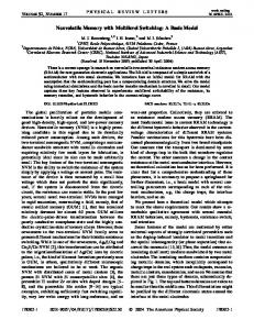
closely-spaced levels may cause them to overlap and thus lead to decoding errors. In this paper we focus on the issue of resistance drift in PCM devices. By means of a prototype chip platform we demonstrate four levels-per-cell storage at large scale. We then illustrate the effect of drift, which causes rapid deterioration of performance in conventional, reference-cell based detection schemes. Finally, we present a new drift-tolerant modulation coding scheme for MLC PCM and demonstrate reliable storage of data for over 30 days at room temperature, with raw bit error rates in the order of 10−5 . II. P HASE -C HANGE M EMORY P ROTOTYPE This section describes the phase-change memory prototype environment that was used in this work. Fig. 1 shows a schematic of the phase-change memory array and cell. The memory array is organized in word-lines (WLs) and bitlines (BLs), with NMOS FET as the selection device. The PCM cell consists of the active phase-change element (PCE), sandwiched between a top and a bottom electrode, that is integrated on top of the access device. The memory cell is of mushroom type with doped Ge2 Sb2 Te5 as the phase-change material. It was integrated in 90-nm CMOS technology using the key-hole process described in [5]. A TEM picture of the PCM cell is shown in Fig. 1. The PCM cells were integrated into a prototype chip serving as a characterization platform [6]. In addition to the PCM cell array (2 × 2 Mcells), the memory chip, illustrated in Fig. 2, contains the addressing, readout, and programming circuitry. In readout, the selected bit-line is biased to a constant voltage (typically 200-400 mV) by a voltage regulator. The sensed current, iread , is integrated by a capacitor, and the resulting voltage is then digitized by an on-chip 8-bit cyclic analog-to-digital converter (ADC). The readout characteristic is calibrated via the use of on-chip reference polysilicon resistors. For programming, a voltage generated off-chip is
Fig. 1. Schematic showing the memory array organized in word-lines and bit-lines, and the memory cell with the phase-change element and the FET access device. A TEM picture of the PCM cell is also presented.
10
7 RTARGET
Resistance (Ohm)
Iterative programming algorithm
10
IPROG(k)
PCM cell
R(k) e(k)
0
6
1
RTARGET
Target Bin 3
10
5
2 VPROG(0) VPROG(1) VPROG(2) VREAD
10
VREAD
VPROG(3)
VREAD
VREAD
4
0
100
200 300 Iprog (uA)
400
500
Fig. 3. Schematic illustrating the basic iterative programming concept using a sequence of adaptive write-and-verify steps.
Fig. 2. Prototype memory chip: (a) circuit diagram, (b) chip micrograph, (c) table summarizing the chip specifications.
converted on-chip into a programming current, iprog . This current is then mirrored into the selected BL for the desired duration of the programming pulse. The memory chip was fabricated in a 90-nm CMOS process with 4 levels of copper interconnect and occupies 2.7 × 2.2 mm2 . The prototype PCM chip is controlled by a FPGA that implements the necessary logic in order to access the memory array and the on-chip electronics. The FPGA also implements the read and write algorithms for MLC operation and controls the off-chip peripherals, including power supplies, reference voltages, and external digital-to-analog and analog-to-digital converters. Finally, the FPGA implements a data acquisition module for rapid collection of measurements and diagnostics. III. M ULTILEVEL C ELL S TORAGE Multilevel PCM is achieved by programming the memory cell into intermediate resistance levels between RESET and SET. The programming space is defined by the characteristic programming curve, which quantifies the change of the cell resistance as a function of the programming current or voltage. Fig. 3 shows the typical programming curve obtained with rectangular programming pulses of decreasing amplitude, when programming starts from RESET. Accurate control of the cell current is necessary in order to achieve multiple resistance levels. In practice, an iterative programming scheme is used to account for cell and access device variability issues that manifest themselves in large memory arrays due to material and/or process variations, and give rise to different programming characteristics among cells. Fig. 3 illustrates the concept of iterative multilevel programming. Starting from a level-dependent “best-guess” programming pulse, the algorithm uses a sequence of write-and-verify steps in order to program the memory cell to the target resistance value. At each
step, the algorithm adjusts the programming current based on the error between the target and the programmed resistance, therefore tracking the programming curve of each cell. The example of Fig. 3 corresponds to a multilevel programming sequence in which the algorithm operates on the partialRESET regime of the programming curve, i.e., melting pulses are invoked in order to partially amorphize the material. This regime allows bi-directional programming as it is illustrated in Fig. 3. In [7], a family of novel programming algorithms is presented and demonstrated to achieve tight, multiple resistance distributions. A. Four levels-per-cell Programming A 200 kcell sub-unit of the prototype PCM array is programmed at 4 levels-per-cell. The target resistance levels were defined in the average programming curve of the array shown in Fig. 3. The two corner levels are programmed with “singleshot” RESET and SET pulses respectively, whereas the two intermediate levels are programmed using iterative write-andverify steps. Each programming pulse is a box-type rectangular pulse. The RESET pulse is a programming pulse of high current, while for SET a trapezoidal pulse of long trailing edge is used to allow sufficient crystallization. Table I lists the definition of the two intermediate levels, in read current, along with convergence statistics. The small number of iterations and high rate of convergence attest to the effectiveness of the iterative write-and-verify algorithm to achieve multilevel programming. TABLE I L EVEL ALLOCATION FOR MLC PROGRAMMING level 0 1 2 3
ITARGET Imin 8.3 uA 12.8 uA Imax
IMARGIN n/a 0.6 uA 0.6 uA n/a
av. no. iterations n/a 2.7 5.6 n/a
convergence rate n/a 98.2% 99.5% n/a
No. Cells (%)
No. Cells (%)
100 ’3’ ’2’ 50
’1’ ’0’
0
(a)
5
50
In this section, a new method to enhance the reliability of PCM devices in the presence of drift is presented. As illustrated in the previous section, drift causes the distributions of programmed resistance levels to shift from their initial positions after programming, and also to move further apart, thus increasing the average resistance margin between adjacent levels over time. At the same time, the spread of each distribution does not change appreciably with time. Therefore, in order to reliably detect the stored levels, appropriate level thresholds would have to be placed between distributions of adjacent levels, and those thresholds would have to be adjusted over time according to the shift of levels due to drift. In practice, adjustment of the thresholds may be achieved by using reference cells, i.e., cells with known stored data, used to estimate the changing resistance values over time. Despite the use of adaptive level thresholds, the bit-errorrate in MLC PCM deteriorates over time, although the noise margin between adjacent levels tends to increase. This is because drift is a random process and thus the increase of the resistance of each cell evolves in a stochastic manner. Moreover, the rate of increase, i.e., the drift exponent v, is itself a random variable. While it is true that the average drift exponent increases with the cell resistance, significant variability is typically observed around the mean values. As a result of this, a small number of cells from each resistance distribution exhibit a distinctly different drift exponent from the rest. The resistance vs time trajectories of two such cells programmed in the adjacent levels ‘2’ and ‘3’ are shown in Fig. 6. It can be seen that, although the cell-levels after programming are apart, they eventually shift closer together and finally cross each other at later time instants, due to drift exponents deviating from the mean behavior. Therefore, in practice, the error-rate in PCM increases over time due to drift. This is a phenomenon that cannot be mitigated simply by adapting level thresholds. One way to deal with it is to enforce redundancy in the form of modulation coding. The main idea of the proposed coding technique lies in the fact that, in the majority of cases, the relative order of cells programmed in different resistance levels does not change due to drift. To this end, information is encoded in the relative order of cell resistance levels within a small group of cells that forms the codeword. In most cases drift does not affect this ordering, thus the codeword can be correctly decoded. A decoding error will occur only when two resistance levels corresponding to two cells of the same codeword cross each other in the course of time, for example due to drift behavior deviating from the average one. However, because of the small number of cells in a codeword, such events are quite rare, giving rise to superior performance, which comes at the expense of some capacity loss. To assess the performance of the proposed drift-tolerant coding scheme, data were encoded and then stored in a subarray of 200 kcells of the PCM prototype chip described above. The codeword length was 7, and the rate of the particular code
(c) 5
10
6
10 Resistance (Ohm)
10
100 No. Cells (%)
100 No. Cells (%)
IV. D RIFT- TOLERANT PCM
0
6
10 Resistance (Ohm)
100
50 (b) 0
5
(d) 0
6
10 Resistance (Ohm)
50
5
6
10 Resistance (Ohm)
10
10
Fig. 4. Time evolution of programmed resistance distributions of 200 kcells due to drift: (a) as programmed, and (b) 40 µs, (c) 1000 s, (d) 46,000 s after programming.
B. Drift of Programmed Levels over Time In PCM, the low-field resistance of the memory cell increases over time, a phenomenon known as resistance drift. Drift affects the stability of the electrical behavior of the device, and thus the reliability of MLC storage. In order to investigate the evolution of the programmed resistance levels due to drift, the programmed array was monitored at different time instances. Fig. 4 shows cumulative histograms of the programmed resistance distributions over time. One observation from these plots is that drift affects all stored levels starting at very short time scales, i.e., µs after programming. The spread of each resistance distribution is due to read noise, cell variability and non-uniform drift dynamics across cells. From the measured data of Fig. 4 one can estimate the average drift behavior as a function of the programmed resistance. Using the drift power-law model [3], i.e., R(t)/R(t0 ) = (t/t0 )v , one can calculate the evolution of the programmed resistance levels over time, and also extract the average drift exponent v for each resistance level (Fig. 5). Here, t0 is set to 40 µs after programming. From Fig. 5 it can be observed that the drift power law model appears to hold for over 9 orders of magnitude in time, over which measurements were made.
0.08 data 6
0.06
Drift Exponent
Resistance (Ohm)
10
model 5
10
0.04
0.02
4
10 −5 10
−3
10
−1
10
1
10 Time (s)
3
10
5
10
0
’0’
’1’ ’2’ Level
’3’
Fig. 5. Evolution of mean programmed resistance values over time and extracted mean drift exponent according to the resistance drift power-law model.
30−days
Level−2 Level−3 Cell (2) Cell (3)
100 90 80
−3
10 BIT ERROR RATE
70 RESISTANCE (kΩ)
1−year
REF−CELL CODE
60 50 40
30
−4
10
−5
10
−6
−5
10
−3
10
−1
10
1
3
10 10 TIME (s)
5
10
7
10
10 −5 10
−3
10
−1
10
1
3
10 10 TIME (s)
5
10
7
10
Fig. 6. Resistance vs time trajectories of two cells programmed at levels ‘2’ and ‘3’. The levels cross each other over time due to drift coefficients deviating from the average ones. Dashed and dash-dotted lines depict the average resistance-time trajectories of all cells programmed at levels ‘2’ and ‘3’, respectively.
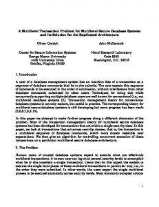
Fig. 7. Bit-error-rate of “reference-cell” and the proposed coding methods on a PCM array of 200 kcells. Measurements have been performed starting at 40 µs after programming and for extended periods of time.
used was 1.57 bits/cell. Other codes can be constructed that have higher rate, at the expense of encoder/decoder complexity or performance. Two detection methods were considered. The first method treats the stored data as uncoded, and applies appropriate level thresholds to detect the stored levels. The thresholds are adaptive, and are calculated at each time instant based on the stored levels in a collection of reference cells. For fairness of comparison, the number of cells that were used as reference cells corresponds to the same amount of capacity loss, i.e., redundancy, as the proposed code. The second method decodes the code applied to the cell array by using a combination of minimum-distance decoding and a sorting operation. The performance of the two methods is illustrated in Fig. 7, where ‘REF-CELL’ and ‘CODE’ denote the first and the second detection method, respectively. Although the two decoding methods have the same overhead, drift-tolerant coding is superior by more than one order of magnitude in error-rate. Even more importantly, the performance of drift coding appears to degrade much more gracefully with time than that of the reference-cell-based scheme, suggesting that it is significantly more tolerant to drift. It is quite impressive that drift-tolerant coding exhibits a raw error rate around 10−5 even after 37 days at room temperature, a result that cannot be matched by a referencecell-based scheme. If the error rates are extrapolated, by assuming a linear trend of bit-error-rate vs log-time, then it appears that excellent performance, i.e., raw error rates well below 10−4 , may be maintained over extended periods of time by using the proposed drift-tolerant coding method. Simple, low-redundancy error-correction codes could then be sufficient to bring the overall error rate down to levels around 10−15 or less, which are required for practical memory devices. Methods that enhance reliability, such as the one proposed, are key stepping stones in the path towards enabling practical memory devices based on PCM. Combined with advances in materials and process technology, they will ensure that a viable roadmap of superior PCM devices can be sustained.
The reliability of multilevel-cell phase-change memory is adversely affected by resistance drift. Reference cells may be used to cope with the shift of resistance levels over time, however their effectiveness is limited due to the stochastic nature of drift. A new drift-tolerant coding method is proposed that is significantly robust to drift, by encoding information in the relative order of resistance levels in a codeword. The new method is demonstrated, in a test memory chip, to be vastly superior to reference-cell based schemes of the same redundancy, thus offering largely enhanced reliability for MLC PCM over extended periods of time.
V. C ONCLUSIONS
ACKNOWLEDGMENTS We acknowledge the support of the entire PCM team at IBM. We especially thank U. Egger at IBM Research - Zurich and Prof. Th. Antonakopoulos and his group at the University of Patras, Greece, for their contributions in bringing up the characterization setup. R EFERENCES [1] R. F. Freitas and W. W. Wilcke, “Storage-class memory: The next storage system technology,” IBM J. Res. Dev., vol. 52, no. 4/5, pp. 439–447, 2008. [2] S. Kim, B. Lee, M. Asheghi, G. A. M. Hurkx, J. Reifenberg, K. Goodson, and H.-S. P. Wong, “Thermal disturbance and its impact on reliability of phase-change memory studied by the micro-thermal stage,” in Proc. IEEE IRPS, 2010, pp. 99–103. [3] D. Ielmini, D. Sharma, S. Lavizzari, and A. L. Lacaita, “Reliability impact of chalcogenide-structure relaxation in phase-change memory (PCM) cells–Part I: Experimental study,” IEEE Trans. Electron Devices, vol. 56, no. 5, pp. 1070–1077, May 2009. [4] A. Pirovano, A. L. Lacaita, F. Pellizzer, S. A. Kostylev, A. Benvenuti, and R. Bez, “Low-field amorphous state resistance and threshold voltage drift in chalcogenide materials,” IEEE Trans. Electron Devices, vol. 51, no. 5, pp. 714–719, May 2004. [5] M. Breitwisch et al., “Novel lithography-independent pore phase change memory,” in Proc. Symp. VLSI Tech., 2007, pp. 100–101. [6] G. F. Close, U. Frey, M. Breitwisch, H. L. Lung, C. Lam, C. Hagleitner, and E. Eleftheriou, “Device, circuit and system-level analysis of noise in multi-bit phase-change memory,” in Proc. IEDM Tech. Dig., 2010, pp. 660–663. [7] N. Papandreou, H. Pozidis, A. Pantazi, A. Sebastian, M. Breitwisch, C. Lam, and E. Eleftheriou, “Programming algorithms for multilevel phasechange memory,” in Proc. IEEE ISCAS, 2011.