INTERNATIONAL JOURNAL OF SATELLITE COMMUNICATIONS AND NETWORKING
Int. J. Satell. Commun. Network. (2013) Published online in Wiley Online Library (wileyonlinelibrary.com). DOI: 10.1002/sat.1025
DVB-RCS2 overview Harald Skinnemoen1,*,†, Christian Rigal2, Ana Yun3, Lars Erup4, Nader Alagha5 and Alberto Ginesi5 1
AnsuR Technologies, Fornebu, Norway 2 Inmarsat, London, UK 3 TAS-E, Madrid, Spain 4 iDirect, Saint Laurent, Canada 5 ESTEC, ESA, Noordwijk, The Netherlands
SUMMARY This paper presents an overview, status, key technologies, and main benefits of DVB-RCS2, as well as the target goals of what is probably the largest standardization effort conducted for satellite communication systems. In addition to the novel technology elements overview and to appreciate the background, basis, and mechanisms involved, we highlight the process and the key research investigations that characterized the standardization effort. We offer a brief comparison with the first-generation DVB-RCS, and we highlight the various profiles for different target use cases and include the latest status of the mobile and mesh capabilities. Finally, we describe the structure of the standard and allow ourselves to share some thoughts of the impact it may have. Copyright © 2013 John Wiley & Sons, Ltd. Received 25 October 2012; Accepted 24 January 2013 KEY WORDS:
DVB-RCS2; satellite; communications; standard; overview
1. INTRODUCTION The second-generation broadband interactive satellite communications standard, Digital Video Broadcasting (DVB) Return Channel via Satellite (RCS)2, is probably the most powerful broadband satellite communications system specification published to date and likely the largest standardization effort conducted for satellite communication systems. A diverse and large group of highly dedicated experts have worked towards consensus for the best overall solutions in a broad area of topics, covering all elements needed for a complete system that can serve a variety of required markets. In addition to a number of projects both at the European Space Agency and the FP6 and FP7 in the European Union, an estimated direct contribution of well over 10 000 workdays by experts worldwide has gone into researching, developing, and defining the new RCS2 specifications. The first generation of DVB-RCS was made at a time where Asynchronous Transfer Mode (ATM) to the desktop was a hot topic; it was focused on optimizing the physical-layer performance in that context. Physical-layer interoperability of equipment from several vendors was achieved with relative ease; however, actual deployment of multi-vendor networks was hampered by the lack of common management interfaces and quality-of-service (QoS) policies. DVB-RCS2 extends the scope of the specifications from being physical-layer and link-layer specifications to a full interactive satellite communications solution for native IP. DVB-RCS2 retains all the functionality of the first generation, including provisions for mobile terminals and mesh networks. DVB-RCS2 was initially completed in 2011, with the mobile and mesh extensions as well as the guidelines in 2012. With the latest additions of the mobile and mesh capabilities, DVB-RCS2+M is ready to serve commercial, professional, and governmental market segments. The lower layers deliver a substantial enhancement in the performance and are also optimized for Ka-band (and higher) frequencies, via technologies such as adaptive coding and modulation in both *Correspondence to: Harald Skinnemoen, AnsuR Technologies, Fornebu, Norway. † E-mail:
[email protected]
Copyright © 2013 John Wiley & Sons, Ltd.
H. SKINNEMOEN ET AL.
forward and return links. A very substantial amount of effort in the standardization process was directed towards defining efficient and scalable ways of translating IP-level QoS to satellite resource management, as well as to define interfaces for equipment and service management. In this paper, RCS1 refers to the first generation DVB-RCS, RCS2 refers to the second generation, and DVB-RCS simply refers to either both or none in particular, thus considering general aspects. This paper is organized as follows: We present the overview, status, key technologies, and main benefits of DVB-RCS2. In addition to the novel technology elements overview, we highlight the process, in particular the research conducted, to appreciate the background, basis, and mechanisms involved. We offer a brief comparison with the first generation DVB-RCS, and we highlight the various profiles for different use cases targeted and include the latest status of the mobile and mesh capabilities.
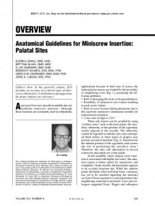
2. DVB-RCS BACKGROUND DVB-RCS is a technical standard, created by the DVB Project [7] in the Technical Module (TM)-RCS working group, defining a complete specification for two-way interactive satellite broadband communications; often referred to as very small aperture terminal (VSAT) systems. Low-cost equipment provides dynamic, demand-assigned transmission capacity to residential and commercial/institutional users. Depending on satellite link budgets and other system design parameters, DVB-RCS implementations can currently dynamically provide several tens of Mbit/s to terminals on the downlink and typically up to 10 Mbit/s from each terminal on the uplink. However, there are no hard limits, and as both are satellite payload technologies, use of higher frequency bands and terminal processing speed evolves, so can the data rates. First-generation DVB-RCS, initially published by ETSI as EN 301 790, in year 2000 has been relatively stable, with the mobile extensions in RCS+M as the largest update until the second-generation update. In addition to a significantly more powerful ‘RCS2’ specification, DVB-RCS2 also includes specifications for the IP layers and for management (higher layer satellite (HLS)). The corresponding RCS2 commercial requirements issued by the DVB project commercial module state that a recognized limitation of the ‘RCS1’ specification is that it covers only the lower Open Systems Interconnection (OSI) layers with the link and air interface, without providing essential supplemental mechanisms on network layer and higher layers. This might lead to interoperability issues with overlying networks solution and between various solution providers. Even though some satellite systems did make use of terminals coming from multiple vendors on the same hub, the effort required for managing these different terminals in a transparent way at operator’s level appeared to be too large for the value it was bringing. Therefore, there was a clear need to standardize protocols also for these higher layers, associated with the user plane as well as the management and control planes. In this respect, the related ‘call for technologies’ was open to proposals concerning the whole set of OSI layers from the physical layer up to the application layer for data, management, and control planes. In its basic form, both RCS generations provide ‘hub–spoke’ connectivity; that is, all user terminals are connected to a central hub that both controls the system and acts as a traffic gateway between the users and, in general, the Internet; also, intranet solutions are possible using Virtual Private Networks (VPN). User terminals typically consist of a small indoor unit and an outdoor unit with an antenna size comparable with a conventional direct-to-home TV receiver. Because DVB-RCS terminals also transmit data, outdoor units include a radio frequency (RF) power amplifier. In addition to the hub-centric architecture, ‘mesh’ extensions have also been specified, allowing direct communication between terminals through a single satellite hop, using transparent or regenerative satellite payloads. It may be noted that the mandatory parts of the RCS interface specification only affects the network terminals because it should be possible to select and acquire any gateway, and be sure that all Terminals on the market can operate with it, even if not all options are implemented (yet) in the gateway (Figure 1).
2.1. Call for next generation When the call for technologies for RCS2 closed on May 4, 2009, 19 proposals were received, showing a broad interest for the work. The objective was to respond with technologies that could meet the commercial requirements approved by the DVB commercial module: Copyright © 2013 John Wiley & Sons, Ltd.
Int. J. Satell. Commun. Network. (2013) DOI: 10.1002/sat
DVB-RCS2 OVERVIEW
Figure 1. DVB-RCS concept.
• RCS-LLS: A specification for an interaction (return) channel for DVB-S2 satellite distribution systems, basically seen as a major upgrade to DVB-RCS (first-generation) physical layer, medium access control (MAC) layer, and IP packet encapsulation. • RCS-HLS: An extended specification required for support of commonly used IP-based protocols and applications (HLS), providing interoperability while increasing and optimizing the performance via best use of the resources. There is also special focus on mesh, mobile, and security, as well as overview specification (RCS-OSL) that mandates special combinations of technologies for the commercial profiles: • • • • • •
Consumer and Small Office/Home Office (SOHO): fixed and fixed-mesh Multi-dwelling: fixed and fixed-mesh Corporate: fixed, mobile, and fixed-mesh Military: fixed, transportable, mobile, and fixed-mesh Backhaul: fixed, transportable, mobile and fixed-mesh supervisory control and data acquisition (SCADA)/transaction: fixed and fixed-mesh
The overall document structure is illustrated in Figure 2.
Figure 2. DVB-RCS next generation and related specification documents. Copyright © 2013 John Wiley & Sons, Ltd.
Int. J. Satell. Commun. Network. (2013) DOI: 10.1002/sat
H. SKINNEMOEN ET AL.
2.2. Market segments DVB-RCS2 – completed 10 years time after the RCS1 – addresses several market segments. In addition to the attractive fact that a standard provides a basis for interoperable satellite terminals and lower cost due to larger volumes, RCS2 provides benefits in several markets: • In consumer markets, the lower cost consumer version will be attractive. • In specialized smaller networks, the flexibility, power, and efficiency will be part of the overall attractive features. • DVB-RCS2 continues the focus on the professional markets, adding sought-after features for security for governmental markets as well. In principle, it may seem optimal if all terminals have the same features to make them completely interoperable. However, we need to take into account the cost of implementing all features for any market and freedom for the manufacturers to develop specific and unique products within the framework of the specification. At the other extreme end of the scale, manufactures would choose what to implement from the specification. This will however quickly become chaotic, as there are too many combinations of features. Hence, the profiles are defined, and once a terminal is to be compliant with DVB-RCS2, at least one profile must be selected where all features of that profile are implemented according to the standard. Service providers or operators would then be able to configure the sets that are to be used in their network. Thus, a careful trade-off and balance has been carried out. Much of the discussion in a standards group boils down to what should be mandatory to implement. There is less debate on whether some technology is better than another, as this is usually possible to agree via simulations or tests. Satellite communications is a niche market compared with mobile cellular networks, and therefore, DVB-RCS2 has carefully balanced the various requirements, specifically eliminating any lack of de-facto interoperability present in RCS1.
3. KEY TECHNOLOGIES 3.1. Adaptive coding and modulation One of the most desired capabilities of the return link of the next-generation RCS is support for adaptive coding and modulation. Already available in the DVB-S2 forward link to the user, it becomes also a feature of the return link to the hub with RCS2. The possibility to adapt coding and modulation (ACM) provides an efficient way of adapting transmission to the maximum capacity possible, rather than adjusting to a possibly conservative, worst-case scenario. This will be able to increase the overall capacity in most current systems. In addition, it is an essential technology for Ka and higher frequency band systems, where the effect of rain fading is much more severe than at Ku-band where most systems operate today. On the return link, it makes the best use of the user’s power amplifier by always using its full power, thus providing the maximum data rate under all conditions. A combination of dynamic rate adaptation, whereby the symbol rate of the carrier is adjusted according to some criteria, as well as ACM may also be exploited to optimize the user QoS when in the presence of strong intra-system interference. A key issue is to standardize the mechanisms to control the capabilities consistently across different implementations. Therefore, effort was spent on identifying and specifying the signaling for ACM in both communications directions. DVB-RCS2 uses the DVB-S2 capabilities for ACM extensively and can benefit well from the full potential. Now that the capabilities are defined, a challenge left to the vendors and operators is how to adapt or configure the multiple options, in both directions, for adaptive, variable, or just constant coding and modulation. One needs to define the basis for adaptation: How it is controlled, how sensitive it is, whether it can be triggered by the higher layers, the channel state or the network operator, and so on. Networks could have different settings, depending on the characteristics of the services offered. Mechanisms are now in place for enabling the best settings. Although applications could be designed, in some cases, to take advantage of the capabilities, the fact will be that most applications would neither be optimized particularly for DVB-RCS2 nor should they be required to be. It is Copyright © 2013 John Wiley & Sons, Ltd.
Int. J. Satell. Commun. Network. (2013) DOI: 10.1002/sat
DVB-RCS2 OVERVIEW
expected that the most common mode of operations will be that the ACM capabilities are triggered from the channel side (as opposed to the source side), for the purpose of maximizing the transfer rate while keeping a desired QoS setting with respect to target packet and BER. 3.2. Support for CPM One of the most debated topics in RCS Next Generation (NG) was the introduction of support for continuous phase modulation (CPM), where amplifiers can be run in saturation (non-linear) mode. CPM efficiency is claimed to be higher than linear modulation if the same Solid State Power Amplifier (SSPA) is used. If a smaller and cheaper SSPA could be used, this should result in lower cost. There is however no agreed value of exactly the cost saved, as this will depend on so many variables, including the number of units produced and what design (linear amplification vs. multiplier) it is compared with. TM-RCS group also concluded that CPM in some cases could provide higher data rates for single users. Findings include the following: Linear modulations have comparable performance with the CPM modulations up to about 1.5 b/s/Hz when considering operations at the Out-Door Unit (ODU) optimum working point or when considering an ODU with limited instabilities. At higher spectral efficiency, linear modulations perform better than CPMs. When taking into account larger ODU instabilities, CPM schemes show better performance than linear modulation. CPM, however, is not expected to be as spectrum efficient as linear modulation Quadrature Amplitude Modulation (QAM) and was reported to not support spectral efficiencies higher than 1.8 b/s/Hz, while linear modulations cover up to 2.5 b/s/Hz. Thus, depending on the specific system, the operational cost increase might outweigh the potential savings in equipment cost. In any case, for the RCS2 terminal, it will be mandatory to support both. Thus, operators can enable the one or the other mode depending on the capabilities of their gateways and the preferred choices. The choice of the modulation scheme may also depend on different criteria such as the power consumption for battery operated terminals. When the ODU uses non-linear frequency multiplication schemes for frequency up-conversion, linear modulations cannot be used, and high-order modulations cannot be supported when considering small terminals because of their limited equivalent isotropically radiated power (EIRP). The drawbacks of CPM then disappear for such users. 3.3. Continuous carrier DVB-RCS+M for mobile, defined in [7], supports using continuous carrier (CC) with DVB-S2 in the return link; even in ACM mode. The baseline is constant coding and modulation, with ACM or variable coding and modulation as alternatives. It is possible to obtain network control center (NCC) control by defining multiple CC types where the terminal can operate. While it is not compulsory to support it, terminals could in principle operate in CC and Multi-Frequency, Time Division Multiple Access (MF-TDMA) mode at the same time for RCS+M, but this capability will be removed for RCS2 to limit the options. The CC mode uses much lower symbol rate on the return link than forward link, which is the main reason why DVB-S2 cannot be used ‘as is’. Delays due to coding/interleaving would become excessive too. Thus, RCS2 will also use a CC version adapted to lower rates with a lower delay coding. Compared with RCS1, where a CC solution can offer a substantial increase in capacity (30%), the gain will be less for RCS2. However, there are mostly other reasons for users requesting the CC capability. For single connections that can directly benefit from this, for example, constant rate video streaming, any gains could be straightforward to explore, but because in CC, the resource management system inherent in the MF-TDMA scheme is lost, it may otherwise require traffic shaping to be carried out at the IP layer for multiple users and sessions. It obviously also requires that there is enough traffic to send; otherwise, capacity would be wasted. In the MF-TDMA return channel, such capacity could be reclaimed for other users more easily. 3.4. Random access A new technology that is to be part of RCS2 is a random access (RA) return link access method. With this solution, it is not required to request capacity in advance – thus, for intermittent data transfer of small capacity, the system will be able to be more responsive by avoiding the satellite round-trip delay inherent to capacity requests to the hub. The access method is of competitive nature, and with too much demand, the channel will lose efficiency and may ultimately get blocked. RA can be seen by terminals Copyright © 2013 John Wiley & Sons, Ltd.
Int. J. Satell. Commun. Network. (2013) DOI: 10.1002/sat
H. SKINNEMOEN ET AL.
as a semi-static rate assignment but may also be seen as a low-data-rate channel. The number of RA time slots a terminal can access in each super frame will not vary much within one traffic session (typically several tens of seconds) but may vary more on a larger time-scale due to aggregated traffic demand. Variations of RA capacity within one traffic session are managed by the NCC. Terminals randomly select slots for data transmission from an available pool, in contrast to the continuous rate assignment, where the slots are assigned to a specific terminal for a large period. While RA will result in some packet collisions on one hand, it will also result in a better reactivity (compared with demand access) or efficiency (compared with continuous rate assignment) for traffic profiles such as web browsing, which are largely asymmetric and may suffer of slow-start effect on TCP sessions. 3.5. HLS and IP over satellite RCS1 was a LL/PHY specification. When it was developed in the late 1990s, ‘ATM to the desktop’ and Integrated Services Digital Network (ISDN) were hot topics but not native IP. As for other proprietary broadband satellite solutions, support for IP was later integrated (even if the name of the system was, unlike some other systems, not changed to reflect this). For RCS2, the system is designed for direct IP transport over satellite, with improved TCP and other IP protocols support, better QoS management, more efficient encapsulation, integrated IP management, Software (SW) download over IP, support for IPv6, and so on. 3.6. QoS management The complete QoS system architecture is revised and improved in RCS2. Key elements include deciding the QoS classes and how these are mapped to the PHY/LL resources. What parameters need to be configured at each level may be tuned too, as does management of layer 2 control and management, and its priority related to the various traffic classes. With several coding and modulation options and return channel formats that include RA, CC, and MF-TDMA, we are looking at an interesting optimization challenge. The exact way to manage the resources needs not be defined, but the capabilities should be defined, as does what is required to make terminals from different manufacturers perform consistently. This is achieved via a set of capabilities advertised at terminal side in a harmonized manner described in the HLS specification. The result is a wide range of optimization parameters that each operator can tune according to its specific traffic profiles and improve over time, even if the customers’ needs change. 3.7. Return link encapsulation In IP communications systems with adaptive coding and modulation, data fields are of variable length, but also, bursts capacity may change. It will depend on the modulation and the coding rate required by the link conditions. The IP data need to be split up and encapsulated into a variable size container for transmission over the lower layers. In the forward link, the generic stream encapsulation [16] over DVB-S2 is used. In the return link, the techniques used in RCS1 are replaced by a new return link encapsulation (RLE). Several options were evaluated, considering the required degrees of freedom that may be needed for future flexibility. All satisfy the basic requirements. Aspects that were considered in the evaluation and harmonization of proposals include the following: • • • • • • • • • • •
Support for parallel IP packet segmentations. Support of regenerative payload. Support of transparent meshed topology. Configurability and flexibility. VPN-transparent tag. VPN-compressed tag. Support of RA. Signaling. Optional error detection capabilities. Efficiency for best effort traffic. Efficiency for real-time traffic.
Copyright © 2013 John Wiley & Sons, Ltd.
Int. J. Satell. Commun. Network. (2013) DOI: 10.1002/sat
DVB-RCS2 OVERVIEW
• Computational efficiency. • SCPC interworking. • Maturity of the technology. 3.8. Error correction coding The main goal is to exploit recent evolution in coding performance, and, for the short bursts sizes on the return link, two turbo codes were proposed: A 16-state turboΦ code and a 3D turbo code, as an extension to the RCS1 coding scheme. Both have the same inventors. Finally, turboΦ has been selected as the coding for the RCS2 in linear modulation mode, as a result of a comparative performance assessment that concluded the following: • TurboΦ is better than the eight-state 3D-TC in all except one test case, with larger minimum distances in most case. • At eight decoding iterations, there is a 0- to 0.2-dB gap in the waterfall region. For five iterations, the gap is up to 0.3 dB. The coding gain of the TurboΦ scheme with respect to the RCS1 turbo code varies according to the modulation, coding rate, and burst sizes, but it approaches values around 1 dB at low-BER values. This extra coding gain can be used by the system to either reduce the terminal transmit power or to increase the spectral efficiency of the system. The DVB-RCS2 lower layer normative document specifies a combination of convolutional coding and CPM as a mandatory feature to be supported by RCS2 user terminals. To maintain the possibility of future enhancements in terms of performance, spectral efficiency, and implementation, a generalized CPM waveform has been defined in the guidelines document for possible future use. 3.9. Antenna alignment One element with potentially considerable impact on the initial cost of obtaining interactive satellite services is the effort required for the antenna installation and alignment. The DVB-RCS2 provides signaling support that facilitates the manual as well as automated alignment of the user terminal antenna based on a two-stage forward link and return link alignment processes. The return link alignment starts only after the forward link alignment is completed, with a level of accuracy that is specified by the gateway. It is possible to develop intelligent search algorithms to calculate the elevation and azimuth of the user terminal antenna as a function of feedback received from the gateway. Such search algorithms may minimize installation duration and can remove the need for manual installation when combined with motorized antenna control equipment. The detail process on the antenna control and automated alignment has been reported in the lower layer guidelines document [4, 5]. 3.10. Security Security aims at providing sufficient confidentially, integrity, availability, and non-repudiation performance. The main security aspects of M-Plans and C-Planes cover the following: • Protection of channel activity, such as hiding information on traffic volumes. • Protection of control and management information for C-Plane and M-Plane signaling. • NCC and terminal authentication – ensuring that only valid terminals can log on to any given network and preventing hub spoofing. Security at the network level is essential for several major applications areas. This includes not only government/military and corporate users but also consumer broadband subscribers who have an expectation of data privacy. This type of security aims at providing sufficient confidentially, integrity, availability, and non-repudiation performance for the application. Security requirements vary widely, from simple data privacy to military-grade encryption and obfuscation. A single security solution is therefore not likely to be both sufficient and cost-effective Copyright © 2013 John Wiley & Sons, Ltd.
Int. J. Satell. Commun. Network. (2013) DOI: 10.1002/sat
H. SKINNEMOEN ET AL.
for all users. Furthermore, the most demanding users in this regard often insist on particular methods, which may be incompatible with the needs of others. To address this, RCS2 does not include any mandatory security provisions, but instead has generic signaling provisions that allow implementation of a large number of different security solutions. The implementation guidelines include three different solutions, ranging from consumer-grade data protection to a full, military-grade, Federal Information Processing Standard (FIPS)-certified transmission security (TRANSEC) implementation. 3.11. Summary of differences between RCS1 and RCS2 Some key technological improvements from DVB-RCS to DVB-RCS2 RCS1 Harmonized management and control Harmonized IP-level QoS Multiple virtual network support Security Return link access scheme for traffic Modulation schemes Channel coding Burst spread spectrum Return link adaptivity Bandwidth efficiency
RCS2
None
Yes (optional)
None None
Yes Yes
Single solution
Support for multiple security systems, for applications with widely different requirements TDMA, continuous carrier TDMA, continuous carrier, random access QPSK Linear: BPSK, QPSK, 8PSK, 16QAM Constant-envelope: CPM 16-state PCCC turbo code (linear RS/convolutional, 8-state PCCC turbo code modulation), SCCC (CPM) Burst repetition Direct sequence Limited support Inherent in air interface (TDMA and continuous carrier) Improved about 30% from DVB-RCS to DVB-RCS2
BPSK, Binary Phase Shift Keying; QPSK, Quaternary Phase Shift Keying; 8PSK, 8-ary Phase Shift keying; PCCC, Parallel Concatenated Convolutional Codes; SCCC, Serially Concatenated Convolutional Codes.
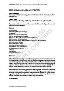
4. RESEARCH AND PERFORMANCE ASSESSMENT ACTIVITIES A study group within the TM-RCS working group has significantly supported the work on the RCS2 specification. Within this group, academic entities as well as agencies have, led by ESA, carried out a number of analysis and computer simulations to assess the performance of the different technologies that have been proposed as part of the Call for Technologies. The results of these activities have been used by the TM-RCS Working Group (WG) as an input for the selection of the final set of specifications. Some examples of the activities carried out by the study group are highlighted as follows. 4.1. Comparative performance assessment The physical-layer waveform has been the subject of extensive comparative performance evaluation of several proposed physical-layer solutions. To carry out this assessment, simulation models of the proposed schemes were collected and used under a common platform (Figure 3). A realistic model for the propagation channel was added, with detailed terminal ODU non-linear characteristics and power instabilities, phase noise, carrier frequency error, and adjacent carrier interference. Within this framework, the following comparisons were carried out: (1) Forward Error Correction (FEC) scheme selection for linear modulation, comparing the performance of the 3D code and Turbo-phi code under similar channel conditions. (2) Linear and CPM performance assessment. (3) Selection of higher order modulation (comparative performance assessment of 16-ary AmplitudePhase Shift Keying (16APSK) and 16QAM modulation schemes). (4) Comparative assessment of linear modulation versus CPM. Copyright © 2013 John Wiley & Sons, Ltd.
Int. J. Satell. Commun. Network. (2013) DOI: 10.1002/sat
DVB-RCS2 OVERVIEW
Figure 3. Block diagram of the return link simulation model.
(5) (6) (7) (8)
Comparison analysis of link-layer encapsulation schemed (RLE vs. Return Link Generic Stream Encapsulation (RGSE)). Comparison between block code versus convolutional code for CPM schemes. Evaluation of the symbol synchronous technique based on single-carrier FDMA (SC-FDMA). Analysis of the benefits of using amplitude modulated pilot symbols within the burst structure.
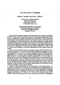
To assess the merit of linear modulation and CPM, system simulations were carried out to assess the performance of each scheme under equal channel conditions. As a reference, a multi-spot-beam satellite broadband network with 96 beams covering continental Europe, a four-frequency reuse ‘coloring scheme’ with 125 MHz per beam, was considered. The assessment was carried out with 1- and 2-watt SSPA saturation power as well as different models for its instabilities. This helped understand the potential return link throughput and peak data rates achievable, as well the relative strength of the linear versus CPM schemes. Indeed, the linear schemes have shown their strengths in providing high spectral efficiencies when the system design is such to allow the exploitation of high-order modulations. CPM schemes have shown their robustness against large SSPA power instabilities as well as more resilience to adjacent channel interference. 5. OVERVIEW OF THE HIGHER LAYERS Whereas the lower layers satellite (LLS) are responsible for providing connectivity and access to the satellite channel, with functions at layers 1 and 2 of the Open Systems Interconnection reference model, the HLS provide IP-oriented functions and the network management of the system. HLS provides a set of protocols and control structures that correspond to layers 3 and 4 functions, enabling DVB-RCS2 to operate seamlessly as an integrated part of IP networks. Whereas standard protocols and functions are and should be used where possible, some IPs and techniques are adapted for enabling and optimizing performance in the interactive satellite environment. In contrast to RCS1, DVB-RCS2 design is IP-centric and uses a novel native IP encapsulation, removing limitations and improving performance over RCS1. IP-centric designs simplify integration with network management and operational tools, for example, allowing DVB interactive satellite services to be incorporated and managed as a component of a wider network service platform. The overall architecture is not only sufficiently flexible to implement several traffic policies for typical Internet services but can also be optimized for specific classes of traffic (Figure 4). The topics covered in HLS are as follows: Copyright © 2013 John Wiley & Sons, Ltd.
Int. J. Satell. Commun. Network. (2013) DOI: 10.1002/sat
H. SKINNEMOEN ET AL.
Figure 4. DVB-RCS2 HLS functional architecture.
• HLS reference architecture as control, management, and user plane, and how higher layer functions can be mapped to these planes. • Satellite virtual network (SVN) addressing. While RCS terminals (RCST) are uniquely identified by a 6-byte label (hardware ID), at logon, they are given a set of 3-byte labels, called ‘MAC-24’ labels, to identify the management entity, configure, control, and manage the operation of the terminal within a satellite network operator’s network. • SVN virtualizing, extending virtualization of independent addressing domains and separation of system resources of satellite services. • IP routing and forwarding functions, utilizing forwarding information base to control which packets are sent to each next-hop interface within the RCST. The forwarding information base contents are derived from the network-layer routing information base. Static and dynamic routing is introduced using OSPFv2 (RFC2328). • IP multicast from the satellite gateway to RCSTs via a method called unidirectional multicast, supporting any-source multicast (RFC1112) or source-specific multicast (RFC3306) from content servers at the gateway or forwarded by the gateway from the Internet. • IP-based differentiated services satellite QoS, with queuing and scheduling models, allowing separation of traffic for classes supported. IP traffic needs are matched to the underlying DVB-RCS2 lower layer capabilities and services that reflect per-hop behavior. Each service is associated with a set of resource specifications at the MAC level. • A PEP negotiation protocol supports use of many, potentially proprietary, Performance Enhancing Proxy (PEP) products (usually not interoperable). In RCS1, there is no standard method to identify what PEP functions are implemented in a Typo (ST), so the NCC could determine what PEP to use. The RCS2 PEP negotiation protocol helps this situation and offers capabilities needed to ensure basic PEP interoperability. • The management plane provides a basis for network management in DVB-RCS2 networks. It establishes a basic framework for DVB satellite networks to be seen as part of the Telecommunications Management Network (TMN) model of telecom network management, helping operators to easily configure and manage RCS networks. • Automatic antenna alignment to control a motorized mount for steering an antenna during installation and general maintenance. A network with misaligned terminal antennas will have reduced capacity, potentially resulting in more intra-sytem and inter-system interference. • The Dynamic Control Protocol allows dynamic connectivity control for regenerative mesh DVB-RCS2 systems and transparent mesh overlay DVB-RCS2 systems. 6. PART 4: OVERVIEW AND OPERATIONAL PROFILES 6.1. Commercial requirements and technical solutions Commercial requirements are in principle agnostic to technical solutions and may thus cite several use cases and markets, as it has carried out in DVB-RCS, covering, for example, consumer, Copyright © 2013 John Wiley & Sons, Ltd.
Int. J. Satell. Commun. Network. (2013) DOI: 10.1002/sat
DVB-RCS2 OVERVIEW
professional, institutional, and multi-user. However, this does not necessarily imply that one technology is needed for each market, preceded by corresponding technical requirements for each of them. Concurrent optimization of technical and economical parameters may lead to different designs for different markets such as data backhauling and consumer markets. While the set of DVB-RCS2 capabilities fulfills all commercial requirements with technical solutions, a ‘one implementation fits all’ solution is commonly not realistic in a commercial setting neither for satellite systems nor many other areas we are used with. In RCS2, we solve this challenge by having different profiles. Profiles are SW configurable sets of solutions targeting specific-use cases. To achieve interoperability between profiles and provide markets with well-defined sets of solutions, profiles have been built from the minimal set of functions as required by the consumer market, as a basic market, and expanding to other VSAT markets by defining dedicated sets of capabilities for those markets. Many of the same capabilities are naturally needed in several different markets, but potentially to a more or lesser degree. This is where the parameters of the capabilities come into the picture. With many capabilities, the number of system implementation variants can quickly become large unless care is taken. DVB-RCS2 is not a toolbox, implementations can pick and choose freely, but neither is there a requirement to implement every element of the standard independently of the market targeted. With N capabilities, there are at least 2N different ‘free’ system implementation options, not counting the parameters. This can quickly become a large number, and profiles limit the number of used sets of solutions while satisfying identified needs. New profiles can also be agreed in the future. Profiles significantly help improve interoperability and testability. In principle, it is not required to have different profiles per market if several could be combined into one common profile. Another benefit of having profiles is that customers will be assured of getting a core set of capabilities while buying a terminal compliant to a given profile. It provides interoperability without having to understand all the details of the implementation at customer’s level.
6.2. Identified markets The commercial requirements identify the following markets that initially are to be covered by the technical RCS2 solution, knowing the advanced technology will soon also find additional markets. • Consumer, characterized by low-cost terminals with acceptable performance and easy installation. • SCADA requires robustness and stand-alone operation with efficiency in smaller networks and low to medium data rates. Professional installation is acceptable, but motorized support could be beneficial in some cases. Very high reliability. • Backhaul; requires high capacity and reliability but will mostly use few traffic profiles and most – if not all – traffic will be of the same type (e.g., voice). • Corporate; mixed traffic, data, voice, web. Database replication from a number of users. Security and reliability are also mandated, as is high capacity. VPN and virtual networks support are important too. • Governmental, where security is a key element, mobility and ad-hoc use as well as operation in small, closed networks. Capacity should be high when needed. • Multi-user; becomes much like supporting multiple consumers of a small business; expected to require similar performance as corporate but more focused towards Internet than intranets.
6.3. RCS2 profiles With the set of technologies, different terminals may implement different capabilities yet still be compliant with selected RCS2 profiles. Networks need not support all capabilities of the specification but select different profiles sets of capabilities and parameters as shown in the following table: Copyright © 2013 John Wiley & Sons, Ltd.
Int. J. Satell. Commun. Network. (2013) DOI: 10.1002/sat
H. SKINNEMOEN ET AL.
Consumer Multi-dwelling Corporate SCADA Backhaul Institutional Physical layer 16QAM return link modulation 32APSK forward link modulation Essential waveform flexibility Fast carrier switching Lowest carrier switching class MAC layer Minimum number of supported traffic SVN Minimum number of layer 2 traffic classes (request classes and allocation channels) Slotted Aloha traffic TRANSEC hooks support Network layer Minimum number of simultaneous traffic multicast streams reception Dynamic IP routing via OSPF support Firewall capability Multicast forwarding on the return link Management layer SNMP v3 support (*) Multi SVNO support
O O O O 1
O O O O 1
M O M M 2
O O O O 1
M M M M 2
M M M M 2
1
4
4
1
4
4
3
3
7
3
3
7
O O
O O
O O
M O
O O
O M
16
64
64
16
16
64
O
M
M
O
M
M
O O
O O
M O
M O
O O
M M
O O
M M
M O
O O
M O
M O
M: Mandatory capability required for this profile. O: Optional capability not required for this profile. (*) SNMP V2c is required as a minimum for all terminals profiles while SNMP V3 should be normative unless specified optional. OSPF, Open Shortest Path First.
As a result of this approach, manufacturers have the option of developing their terminals and/or their hubs to meet one or more of the different profiles. One should note that hubs expect a terminal to implement all functions that are defined normative within a profile and then can drive the usage of a terminal, even if it is for a third-party vendor. If terminals would not fully implement the normative parts of a given profile, it would result in reducing interoperability, which is one of the major goals in RCS2.
7. IMPLEMENTATION GUIDELINES While the three normative DVB-RCS2 documents provide specifications on the lower layer (LLS), higher layer (HLS), and the overall system (OSL) aspects, relevant configuration examples, implementation details, recommended practices, and informative elaborations helping secure full terminal-hub interoperability are found in the guidelines documents. Also, the RCS2 implementation guidelines are organized in separate volumes: the lower layer and the higher layer guidelines documents. Some key examples of topics from the guidelines documents are highlighted in the following sections, whereas other important topics such as RA and security aspects for different application profiles are presented separately in companion articles. 7.1. Forward and return link implementation The lower layer guidelines document explains the forward link, the return link, and the lower layer signaling. On the forward link, the practical use of DVB-S2 features, such as ACM operation; the Copyright © 2013 John Wiley & Sons, Ltd.
Int. J. Satell. Commun. Network. (2013) DOI: 10.1002/sat
DVB-RCS2 OVERVIEW
selection of FEC frame size; and the recommendations on the explicit protection of service data units are described. Guidelines on the use of lower layer signaling components have also been provided. For the return link, implementation of the new Turbo FEC decoder and associated complexity is elaborated. An overview of algorithmic complexity of implementing the CPM transmitter and receiver is also highlighted. The guidelines provide a detailed description of the RLE principle interfaces and elaborates on the implementation of sub-layers of the RLE protocols. The RLE protocol has several features, configured differently for different DVB-RCS2 systems, where different sets of fixed/configurable parameters and options are defined in RLE profiles. Different profile examples, such as star, regenerative mesh, and mesh overlay, are described. The guidelines also provide information on the reassembly process including the error checking algorithms. 7.2. RCS terminal deployment The overall architecture of the user terminals, examples of frequency use for transmit–receive, and regulatory constraints for both fixed and mobile RCSTs are presented in the lower layer guidelines document. Examples of bidirectional communications used between the indoor and outdoor units are described, including implementation protocols for coaxial cables and Ethernet control interfaces. Guidelines for antenna alignment procedures and requirements and alignment accuracy are also covered. 7.3. System implementation guidelines Performance examples of RCS2 sub-systems are provided as part of a system performance evaluation, along with dimensioning and network capacity assessment. Examples of such characteristics include typical phase noise characteristics, carrier stability, amplitude variation, IQ imbalance, and spurious levels of the RF signal at the RCST out. The guidelines also provide typical performance of the physical layer in the presence of channel impairments. Performance results are offered for different physical-layer bursts with payload size, code rate, and modulation types according to the RCS2 burst definitions. Representative efficiency results for link-layer encapsulation have also been included. Several examples of link budget analysis as well as system capacity assessment, based on a representative of system scenario, are presented. 7.4. Transparent mesh overlay networks DVB-RCS2 systems can provide a mesh overlay network with following extensions: • Mesh-capable terminals must be equipped with a DVB-RCS2 compatible burst receiver (possibly with a wideband multi-carrier processing capability) to receive MF-TDMA burst transmissions from other mesh RCSTs. This receiver will operate concurrently with the DVB-S2 compliant receiver for the reception of the TDM Forward Link from the Feeder. • The RCST router supports IP routes for use within its mesh satellite subnet. • Mesh-RCSTs support Dynamic Connectivity Protocol (DCP) client part, enabling on-demand mesh link establishment. • The network control center has a mesh controller, which implements the server part of the DCP and which is responsible for mesh link management and control, as well as mesh routing. Enabling on-demand direct links between Mesh-RCSTs creates full mesh networking. This ‘on-demand’ is initiated by traffic requests, expressed as a link request (containing sufficient information) to a mesh controller, so it can identify the correct link destination, IP hosts reachable, and the applicable link service specification. The higher layer guidelines document provide information on routing, multicasting, and QoS support, specifically in transparent mesh overlay networks as well as regenerative and transparent star networks. 7.5. Dynamic connectivity The DCP is defined in the DVB-RCS2 higher layer specification as a control signaling protocol between the NCC and the user terminals. Mesh-RCSTs (transparent or regenerative) support DCP Copyright © 2013 John Wiley & Sons, Ltd.
Int. J. Satell. Commun. Network. (2013) DOI: 10.1002/sat
H. SKINNEMOEN ET AL.
protocol for mesh link establishment for DVB-RCS2 in both regenerative and overlay mesh systems. The higher layer guidelines document provides examples and definitions of different messages sequence diagrams for mesh regenerative and mesh overlay networks. 7.6. Future extensions The guidelines provide selected optional capabilities for DVB-RCS2. These are aimed to address specific system profiles or provide possibility of future improvements in performance, spectral efficiency, or implementation. Examples of such capabilities are as follows: • SC-FDMA • Time slot sharing solutions. • Forward link spreading. SC-FDMA is a known access scheme in terrestrial networks, adopted in the uplink of Long-term Evolution [5–8] mobile networks. It is also finding its way into the satellite communication systems, having recently been adopted in the satellite component of DVB-NGH (next-generation handheld) [9–12]. SC-FDMA can increase spectral efficiency by zero roll-off waveforms and simplify implementation of multi-carrier demodulators. Time slot sharing is an effective solution for increasing the bandwidth efficiency of mesh connections over transparent satellites. The technique relies on the fact that two peer terminals, if served by the same beam, may reuse the same time slot as each peer is able to cancel its own signal from the received signal, thus allowing it to demodulate the unknown signals coming from the other terminal. The DVB-RCS2 envisages use of spread spectrum techniques for the forward link, particularly useful for connectivity to mobile RSCTs with small antennas, as well as for extending operating ranges in the presence of atmospheric fading (to maintain availability of the link in Ka or higher frequency bands). In the guidelines document, two alternative solutions are provided for the forward link spectrum spreading, namely direct sequence spectrum spreading and frame repetition spectrum spreading. Each technique has strengths and weaknesses, which make them suitable for different applications. While the direct sequence spectrum spreading solution is very robust against carrier instability, it is not fully compatible with the DVB-S2 waveform and therefore cannot share the same carrier. On the other hand, the frame repetition spectrum spreading solution can co-exist with conventional DVB-S2 waveform in a compatible manner, but it is less effective when channel impairments such as carrier phase instability due to the phase noise are considered.
8. DISCUSSIONS Although the first version of DVB-RCS was a success in some markets, it did not lead to the hoped-for breakthrough in use in other segments – most notably the consumer market. Moreover, as a European initiative, it was initially embraced by European satellite operators. With the largest VSAT market being in the USA, there were larger volumes, and thus by logic of increased production volume, prices became more competitive. This was in no way because of DVB-RCS being intrinsically too expensive but rather the fact that RCS1 lost out some of the potential by lack of interoperability at the higher layers, so providing users less real benefit of being a standard. While cellular operator and equipment manufacturers have recognized that they are both competitors and partners in developing the overall market, the satellite communications community has not been as harmonized and, to a larger degree, fragmented into niches, segments, and regions. Moreover, fixed VSAT equipment does not demonstrate the same direct and immediate need for interoperability as mobile phones and satellite broadcast receivers do. Satellite communications services have traditionally been kept within single-operator networks, where the service and the equipment have been provided by the same entity to the end users. This ties customers, satellite network operators, service providers, and equipment manufacturers into Copyright © 2013 John Wiley & Sons, Ltd.
Int. J. Satell. Commun. Network. (2013) DOI: 10.1002/sat
DVB-RCS2 OVERVIEW
one unity that misses out, sometimes even intentionally, on the benefits of open standards. One of the objectives of RCS2 is to provide benefits in opening up a larger market overall and not just benefits within the ‘islands of SatCom’ as of today. There at the time of market introduction for DVB-RCS2, in principle, three scenarios one can identify: • Success: This is clearly the objective. In this case, more players than before will support, use and produce equipment. There are more players involved this time, specifically from the equipment manufacturers side. While the first time around, in 1999, the RCS initiators invited a core group of European operators, and the RCS1 specification was developed in essence by very few. This time the effort is global with players from Asia, America, Europe, and Middle East. There is an active participation from a large number of stakeholders, where the whole community has learned from the 1st Generation RCS, and was motivated to develop the second Generation. If the players involved actually start rolling out suitably compliant equipment and services, dominating global players will support DVB-RCS and offer compliant equipment. This will likely spark a shift into a higher gear and provide further momentum. • Failure could happen if the standardization process did not result in a good-enough specification or if there were too many degrees of freedom with the risk that even DVB-RCS2 compliant and certified equipment may not be fully interoperable across different brands. Therefore, specific care has been taken to avoid this, but some compromises will always need to take place in a collaborative environment. Too many degrees of freedom could result in a confusing market scenario as well as a too-complex type-approval regime. It could be hard to market what exactly is DVB-RCS2, and the future of RCS could be challenged. • Status Quo could happen if we got a halfway good result that in a way perhaps continues to interest the same user groups as today, but without capturing the attention, interest, and approval of new and larger groups. Most likely a niche market segment will remain, specifically for those governmental market segments that need to refer to a standard and who need multiple independent offers during procurements. There are also certain types of advanced and highly flexible network configurations in the top-end market that may find DVB-RCS the best option. It is difficult to say if there in this case will ever be a third generation, but if it happens, it will be well into the future. ACKNOWLEDGMENTS
The authors would like to acknowledge the support of ESA/ESTEC and SatLabs, as well as the valuable contributions of the active participants in the TM-RCS group. REFERENCES 1. ETSI, TS 301 545-1 Digital Video Broadcasting (DVB); Second Generation DVB Interactive Satellite System (DVB-RCS2); Part 1: Overview and System Level specification 2. ETSI, EN 301 545-2, Digital Video Broadcasting (DVB); Second Generation DVB Interactive Satellite System (DVB-RCS2); Part 2: Lower Layers for Satellite standard 3. ETSI TS 101 545-3, Digital Video Broadcasting (DVB); Second Generation DVB Interactive Satellite System (DVB-RCS2); Part 3: Higher Layers Satellite Specification 4. ETSI, TS 101-545-x, Digital Video Broadcasting (DVB); Second Generation DVB Interactive Satellite System (DVB-RCS2); Guidelines for Implementation and Use of LLS: EN 301 545-2 5. ETSI, TS 101-545-x, Digital Video Broadcasting (DVB); Second Generation DVB Interactive Satellite System (DVB-RCS2); Guidelines for Implementation and Use of HLS: EN 301 545-3 6. Satlabs System Recommendations: http://satlabs.org/activities/169-satlabs-system-recommendations 7. The DVB Project, http://dvb.org. 8. ETSI EN 301 790 V1.5.1 (2009-05), Digital Video Broadcasting (DVB); Interaction channel for satellite distribution systems 9. 3GPP TS 36.300 v8.7.0, Evolved Universal Terrestrial Radio Access (E-UTRA) and Evolved Universal Terrestrial Radio Access Network (E-UTRAN); Overall description; Stage 2, Release 8 10. 3GPP TS 36.211 v8.4.0, Evolved Universal Terrestrial Radio Access (E-UTRA); Physical Channels and Modulation, Release 8 11. 3GPP TS 36.212 v8.4.0, Evolved Universal Terrestrial Radio Access (E-UTRA); Multiplexing and Channel coding, Release 8 12. 3GPP TS 36.213 v8.4.0, Evolved Universal Terrestrial Radio Access (E-UTRA); Physical layer procedures, Release 8 13. Digital video broadcasting (DVB); transmission system for handheld terminals (DVB-H), ETSI EN 302 304 V1.1.1 (2004-11), European Telecommunications Standards Institute. 14. DVB-NGH, Next Generation Handheld, http://www.dvb.org/technology/dvb-ngh/index.xml 15. DVB.org. Commercial Requirements for DVB-NGH, http://www.dvb.org/technology/dvb-ngh/DVB-NGH-CommercialRequirements.pdf 16. ETSI TS 102 606 V1.1.1 (2007-10), Digital Video Broadcasting (DVB); Generic Stream Encapsulation (GSE) Protocol Copyright © 2013 John Wiley & Sons, Ltd.
Int. J. Satell. Commun. Network. (2013) DOI: 10.1002/sat
H. SKINNEMOEN ET AL. AUTHOR’S BIOGRAPHIES
Harald Skinnemoen (MSc’85, PhD’94) is Managing Director at AnsuR Technologies AS, which he founded 2005. His responsibilities are mainly technical and in business development, but include all elements of running an SME. His background is on digital communications systems, information theory and signal processing. He has also been the Chairman of the DVB TM-RCS since 07. Previously he was also Chairman of the ETSI WG TC SES/BSM, and has contributed to standards work for over 15 years. Before he founded AnsuR he was Chief Scientist at Nera SatCom, where he stared ’87, working with most elements of Inmarsat and Fixed VSAT systems.
Christian Rigal (Sup’Aero 86) Manager in the Global Xpress Technology group at Inmarsat Ltd (UK). Working on terminals development and approval for Global Xpress with a particular focus on mobility aspects of the system. Previously Project manager and advanced engineering manager at Thales Alenia Space (FR), leading the system engineering group of communication systems for physical and access layers. Interested in VSAT systems architecture, physical and access layers algorithms simulations as well as satellite architecture design.
Ana Yun graduated from the Polytechnic University of Madrid (UPM), and has a research PhD in the area of SATCOM and Next Generation Networks.Ana has more than 15 years experience in telecommunication networks specialized in SATCOM systems, through Alcatel BELL, HP Consulting and since 2001 in Thales Alenia Space (TAS), where she is responsible of the SATCOM Services and Solutions group and is TAS representative in international standardization bodies (ETSI, DVB, NATO).
Lars Erup (BSEE ’78) is Senior Technical Advisor at VT iDirect. Responsibilities include systems architecture, with special focus on the interactions with physical layer, MAC layer and regulatory aspects. Research interests include modem algorithms and resource management for adaptive systems. Mr. Erup has previously been with Advantech/ EMS Satellite Networks and with the European Space Agency.
Nader Alagha received his Ph.D. Degree in 2001 in Electrical and Computer Engineering from McGill University, Montreal Canada. In 1999 he joined Space and Technology group at EMS Technologies Canada in Montreal. From 2004 to 2006 he was appointed as a Senior Member of Technical Staff at Advantech Satellite Networks (Former EMS Satellite Networks) where he was involved in R&D projects related to the interactive satellite systems based on DVB-S(2)/RCS Standards. Since 2006 he has been with the Technical Directorate at ESA Research and Technology Centre (ESTEC) in The Netherlands. He is involved in several Satellite Communications projects related to the next generations of satellite broadband networks. He has been the editor of the Lower Layer Guidelines Document for the next generation of interactive satellite system Standard DVB-RCS2. Dr. Alagha is an executive
Copyright © 2013 John Wiley & Sons, Ltd.
Int. J. Satell. Commun. Network. (2013) DOI: 10.1002/sat
DVB-RCS2 OVERVIEW
committee member of the IEEE Benelux Chapter on Communications and Vehicular Technology. He served as the General Chair of the IEEE sponsored workshop on Signal Processing for Space Communications (SPSC) in 2008. He has also been a member of Technical Program Committee of several international conferences including the IEEE GLOBECOM. A. Ginesi was born in Parma, Italy, in November 1967. He received the Dr. Ing. cum laude) and Ph.D degrees in electronic engineering from University of Pisa, Italy, in 1993 and 1998, respectively. In 1996-1997 he spent one year at Carleton University, Ottawa, Canada, doing research on digital transmissions for wireless applications. In 1997, he joined Nortel Networks and in 2000 Catena Networks, both in Ottawa, Canada, where he worked on Digital Subscriber Loop (DSL) technologies and contributed to the definition f the second-generation ADSL standard. Since 2002 he joined ESA Research ad Technology Centre (ESTEC), Noordwijk, The Netherlands, where he is currently covering the position of the Head of the Communication-TT&C Systems & Techniques Section. His main current research interests lie in the area of advanced digital satellite communication systems and techniques from theory to HW implementation.
Copyright © 2013 John Wiley & Sons, Ltd.
Int. J. Satell. Commun. Network. (2013) DOI: 10.1002/sat