21st Annual IEEE International Symposium on Personal, Indoor and Mobile Radio Communications
Dynamic Compartment Formation for Coverage Optimization of Cognitive Wireless Networks Apostolos Kousaridas and Nancy Alonistioti
Andrej Mihailovic
Department of Informatics and Telecommunications University of Athens, Athens, Greece {akousar, nancy}@di.uoa.gr
Centre for Telecommunications Research King’s College London, London, UK
[email protected]
Abstract—This paper presents the functionalities involved in enabling the use of compartments in wireless access networks for achieving capacity and coverage optimization. Compartments are defined as dynamic medium-term federations of collaborating elements for intelligent organizational purposes. The work presented in the paper uses compartments as a self-management apparatus for emerging wireless access environments and proposes a compartment formation algorithm for achieving selfoptimization of the coverage of access points. Facilitation of the compartment apparatus is founded in the synergy of selfmanagement tools and the application of cognition in operations of Future Internet networks. The paper presents the details of cognition managers in access points for localized management by forming compartments and proceeds to the analysis as well as providing results in coverage optimizations of wireless networks. Keywords; coverage self-optimization, compartments formation, wireless networks, cognitive management
I.
INTRODUCTION
optimal configuration of the APs, as regards the coverage optimization goal. Our work addresses the abovementioned technical aspects. As regards the first challenge, our work proposes the deactivation of one more APs under certain conditions. This approach follows existing research work for coverage optimization, focusing on specific configuration parameters that could be either offline (e.g., planning of APs placement) or online managed (e.g., power control, distributed channel allocation) [1]-[3]. In such cases the de-activation of a group of APs could improve the network performance and avoid harnessing radio and energy resources. In specific geographical areas, the potentially available wireless resources (i.e. APs) overcover for a long period of time, the existing capacity requirements (e.g., throughput, number of users). Thus, the de-activation of a set of APs could be beneficial for over-served network areas, with possible re-activation when the network conditions necessitate more capacity.
In recent years there has been a continuous increase in the number of wireless access points (e.g., IEEE 802.11) that are placed at several areas (offices, homes etc) following the vast proliferation of capacity requirements for emerging and future Internet services. All these access points (APs) are often not part of the same administrative entity, and the configuration of their locations and operational features are not necessarily planned for the “network welfare”. The uncontrolled operation of wireless APs results in dense topologies of APs, especially in urban areas, with high coverage or frequency overlapping.
An AP de-activation means that it is set to a standby/idle mode, where it does not transmit beacon packets and user equipments (UE) are not able to detect its presence. The latter is achieved through the de-activation of some wireless interface capabilities (RF, baseband). In [4], the authors study the AP entering the standby mode on inactivity detection. However, the key novelty of our work is that it goes one step further by proposing the de-activation of one or more APs, if there is an important overlapping coefficient on a specific geographical area, comparing to the capacity requirements.
The abovementioned environment raises various technical problems and challenges:
The second challenge is investigated by proposing the incorporation of a cognitive management agent per AP so as to reduce the need for human intervention and automate its management. In this direction, APs’ situation awareness development is an essential task for enabling in-network and localized management. In order to address the third technical challenge and build the required situation awareness that is necessary for locally solving the coverage self-optimization problem, we propose the formation of compartments among the involved APs. This approach facilitates the optimal configuration of neighboring APs, and specifically the optimization of their coverage. Although our approach is applicable to a wide variety of network parameters and for many optimization tasks (e.g., channel re-allocation) this work
•
the continuous coverage and capacity optimization of the next generation wireless communication networks, taking also into account the volatile network conditions.
•
the high complexity of the access points’ network condition and the fact that they are owned by different administrative entities ask for localized and in-network management of coverage optimization.
•
the deployment of the coverage optimization should take into account the stimuli of the surrounding telecommunication environment so as to lead to the
978-1-4244-8016-6/10/$26.00 ©2010 IEEE
2255
focuses on the activation and de-activation of APs, which is a very challenging operational capability, as presented above. The reminder of the paper is organized as follows: In section II, the logical architecture of the Network Element Cognitive Manager (NECM) is presented. The algorithm for the formation of compartments of APs is discussed in section III, as well as how the cognitive manager interacts with the compartment management apparatus, for the coverage selfoptimization problem. Section IV describes the scheme for coverage self-optimization by using the established compartments in a specific network area of APs. Finally, performance results for the compartments formation algorithm, as well as the effect of the latter on the behavior of the coverage self-optimization scheme are discussed. II.
NETWORK ELEMENT COGNITIVE MANAGER
As introduced earlier the incorporation of a NECM at network equipment level (e.g., AP) is required for the selfmanagement capabilities and specifically the localized coverage self-optimization. The NECM can be considered as a kind of software agent that resides in network devices and contains the fully realized features of the cognitive cycle represented as Monitoring-Decision Making and Execution [5]. Figure 1 shows some of the main elements of the cognitive cycle focusing on steps required for reaching a decision on taking a specific execution action by the element. One of the main prerequisites for achieving the steps of the cognitive cycle is in the self-awareness plane, seen as the product of the continuous activity in network elements, and their interactions with neighboring elements. From the practical point of view, self-awareness is seen as the elements’ view on the internal and external processes, statuses and states. Monitoring feature is intended to provide the basis for intelligent deduction processes in network elements represented in the situation awareness [5]. Situation awareness is the additional ability to know and deduce what is happening in the network (e.g., faults, optimization opportunities), involving the comprehensive set of data inputs and related to the environment in consideration. Situation awareness is the step that precedes and constitutes the foundation for decision- making. Thus, decision making has the full awareness of the system statuses represented in the situation resembling a view or comprehension that a network administrator would have when a certain event is obtained and analyzed from the current operational aspects in the system. Self-Awareness
Update of operational states
Situation Deduced
Situation Awareness Sensing
Filtering
Monitoring
Assessment of Environment
Characterisation of operational states Level 1
Level 2
Decision Making / Reasoning
Projections - Level 3
Situation triggers
Interpretation library of operational states
Deduction Completion
Procedures for Assessment of Environment
Knowledge Base
Figure 1. Logical arcitecture of a NECM
Intelligence for Decision-making
Action
Monitoring leads to Level 1 of situation awareness, which is the stage for characterization of operational states/perception (e.g., high load). Level 2 of situation awareness realizes the assessment of the environment, analogous to network administrator response to an event/information. When there is a situation trigger the environment needs to be assessed in order to prepare for decision-making. Level 3 of situation awareness is called projections and includes prediction on what would happen in the future based on the current assessment of the environment and/or what conditions should be met to proceed to decision-making. These steps precede decision making where actions are specified subject to the specific invocation of the cognitive cycle. III.
COMPARTMENTS OF NECMS
In this section, the compartment management apparatus as well as the algorithm for the formation of compartments among the NECMs are presented. A. Compartment Management Apparatus Compartments can be defined as dynamic medium-term (or in some occasions opportunistic) federations of NECMs that enable network devices collaboration for distributed monitoring and decision making processes. The formation of compartments among network devices (e.g., APs in this work) is promoted for synergistic tackling of various management problems, by extending individual NECMs monitoring, situation awareness capability and decision making capacity (e.g., APs de-activation) through NECMs collaboration. Two types of nodes constitute a compartment: a) the Simple Member, and b) the Head (Figure 2). The Head collects and composes the information provided by simple member NECMs of the corresponding compartment. Capitalizing on the collected NECMs status/self-awareness, the Head builds a greater view of the status of the compartment area (i.e. compartment level self-awareness) and thus identifies faults or optimization opportunities that each simple member NECM cannot handle individually. Then, it has the capability to make decisions about configuration actions that could be executed by one or more simple member NECMs. The Compartment Management Apparatus (CMA), which is available in the network device (e.g., AP) includes these mechanisms that are needed for the formation of compartment structures and the cooperation among NECMs, as it is depicted in Figure 3. B. Compartments Formation Algorithm A complete compartments formation scheme includes both borders specification and heads’ election. In the literature there are several clustering algorithms, which are mainly targeting wireless sensor networks or mobile ad-hoc networks, but the majority of them is application-specific (e.g., energy-efficient, mobility-aware) [6]. For that reason, we propose a new algorithm for compartments formation that is applicationagnostic. Its main goal is to form these groups (overlays) of APs and select these Heads that will enable the development of the required situation awareness, having covered adequately the respective network area, for various network management tasks and specifically for coverage optimization, in this paper.
2256
This algorithm is based on the topological characteristics of the network area (APs degree, diameter of the network area), and the compartments are created by a process of “preferential attachment”, according to which members prefer to make a connection to the more popular existing members. The distributed mechanism for compartments formation that is proposed in this section takes into account the low or zero mobility levels of the APs and their long operational period. All APs have the capability to discover their physical topology and then using the common known scheme form in a distributed way the appropriate number of compartments. Two APs are considered neighboring if they are within each other’s transmission range. It should be noted that the communication between the NECMs, necessitates the existence of a cooperation channel. Also, we should clarify that after an AP de-activation, its cooperation channel remains active for interaction with neighboring NECMs and possible re-activation of the AP, in the future. The proposed algorithm for compartments bootstrapping is described as follows: Let N={N1 ,N2 ,N3 ,....,Nn }, n∈ℵ be the set of the APs of a network area. 1. Each node i ∈ N (i.e. AP) discovers one-hop away neighbors ( Nik ={Ni1 ,Ni2 ,Ni3 ,....,Nik }, k ∈ℵ ) and calculates its degree Di .
2. Each node i ∈ N advertises to one-hop away nodes ( Ni ) its degree Di . 3. Each node i ∈ N , having collected the neighbors’ degree, identifies its Head ( Hi ) storing the degree of the latter ( DH ) and the distance in hops ( Hopsi ); The node with the higher degree (including the degree of itself) is elected as a head:
max {Dk , Di }, ∀ Nik ={Ni1 ,Ni2 ,Ni3 ,....,Nik }, k ∈ℵ 4. Each elected Head (H) advertises k hops away (e.g., advHops = 2 ) its Degree. The member nodes of neighboring compartments select the Head with the higher degree (and consequently compartment to join). 5. Heads that consist of a small number of member nodes (e.g., mFactor = 2 ) as well as the respective associated simple member nodes are merged with the neighboring compartments that have the most dominant head. The dominance coefficient of a candidate head is increased proportionally to the total number of simple member nodes (memNodes) and inverse proportionally to the number of hops between these two heads (dHops): HeadDominance = w1 * memNodes + w2 * (1/dHops) ,
(1)
where w1 and w2 are weighting parameters (w1 > w2). The head of the neighboring compartments that has the maximum value of equation (1) is selected to merge with the respective head, which has a small mFactor value and has triggered step 5. The continuous reorganization of the formed compartments and Heads re-election is not considered efficient, since the
H
A
A
C
C E
B
E
B
D
H
Compartment Head NECM
H D
D
Compartment Simple Member NECM
Figure 2. Simple compartment structures
signaling cost for updates will increase the complexity and possibly eliminate the advantages of established compartments (e.g., causing ripple effect phenomenon). Hence, in order to fine-tune the formed compartments, after several topological changes, the compartment bootstrapping process, described above, could be periodically repeated on a greater timescale. IV.
WIRELESS NETWORKS COVERAGE SELF-OPTIMIZATION
This section presents our algorithmic model for wireless networks coverage optimization and specifically for the dynamic de-activation or re-activation of a group of APs in a network area, according to the existing capacity requirements. Figure 3 depicts how the NECM framework could be used in conjunction with the CMA, supporting the coverage optimization of a network area. Specifically, the left side of the figure presents the main elements of the NECM that is placed at the AP, having the role of the simple member node of an established compartment. The Monitoring and Action functionalities of the simple member node, for the coverage optimization, are mainly based on the data link layer capabilities of an AP (radio resource management, connection management, network discovery, sleep mode). On the right side, the NECM of the Head (H) of the compartment collects information from the constituent NECMs (Transmit Local Status) in order to update its awareness (Update Compartment Status Awareness). Utilizing this awareness, the Head is able to proceed with situation deduction about the load and coverage level of the compartment area and decides on the activation or de-activation of an AP for coverage self-optimization. The scheme for the coverage optimization is analyzed below and it is illustrated in Figure 4. After the establishment of the compartments, each simple member node (NECM) scans periodically the wireless medium in order to discover the neighbouring APs (physical topology), thus building/updating its adjacency matrix. The MAC addresses and the channels used by each neighboring AP are sensed and kept locally. Furthermore, each member node (AP) requests the associated UEs to provide the MAC addresses list of the sensed APs. The NECM of the simple compartment node collects periodically the above data, builds its Local physical Topology Graph (LTG), and transmits LTG to the Head. Moreover, each AP’s NECM provides to the Head information about its operational status: a) the number of the associated UEs, b) the used capacity (downlink/uplink), as well as c) the total available capacity of the AP. The list of the transmitted parameters is summarized, as follows:
2257
Compartment Management Apparatus Compartment Bootstrapping
Compartment Maintenance
Transmit Leave a Compartment Local Status
Head Feedback
Compartment Bootstrapping
Self-awareness Load Levels, Capacity Usage
Events
Knowledge base Situation Awareness Level 1
Level 2
Decision making
Level 3
Action
Compartment Maintenance
Update Compartment Status Awareness
NECM – Head of the Compartment
Self-awareness
Compartment Topological graph
Compartment Level Load Levels, Capacity Usage
Knowledge base Situation Awareness Level 1
Level 2
Level 3
Decision making
Action
Access Point (Application Layer)
Access Point (Application Layer)
NECM – Simple Compartment Member
Local Topological Graph
Compartment Management Apparatus
Monitoring (e.g. SNMP), correlating
Layer 2 Radio Resource Management
Connection Management
Network discovery, selection and entry
Access Point (Layer 2)
Sleep Mode/power Saving
Mobility Management
Figure 3. Instantiation of an access point NECM for coverage optimization
APUEs,i : Number of Associated UEs to AP i APCap,i : Capacity used of AP i APCapAvail,i : Maximum Available Capacity of AP i UE Cap,j: Reserved Capacity for each associated UE j A(i): Set of APs that are sensed by AP i (one hop away APs) A e (i): Set of APs that are sensed by UE e that is associated to AP i
According to the population of the compartment, the Head receives the monitoring data (e.g., LTG) and the local operational status ( APCap,i , APCapAvail ,i ) from the member nodes and updates its self-awareness about the compartment area by building the Compartment-level Topology Graph (CTG). The NECM of the Head undertakes to characterize the existing load levels in the compartment area, consisting of n APs, through the Capacity Usage Ratio, CUR = n APCap,i . (2)
∑ AP i=1
CapAvail,i
Thereinafter, the Head proceeds to the identification of the coverage optimization opportunities for a Low Load or High Load situation (Level 2 Situation awareness). An optimization opportunity for a Low Load situation indicates that there is the possibility to de-activate one or more APs; the goal is to avoid the harnessing of resources in the compartment area, without concurrently reducing the effective geographical coverage of the APs. Similarly, in a high load situation the Head estimates the necessity to re-activate an AP in order to address the increased capacity requirements. The Coverage Optimization Opportunity Coefficient (COOP) is given by:
COOP = CUR OF ,
(3)
where the Overlapping Factor (OF) denotes the coverage of the APs that constitute the compartment area and it is provided as follows: OF =
Edges . CN *(CN - 1)
(4)
Edges parameter corresponds to the number of the existing connections (i.e. overlaps) among the APs of the compartment, while CN is the number of APs (i.e. Compartment Nodes) that constitute a compartment. Through equation (3), the CUR is associated with APs OF in the corresponding network area. This allows the more effective interpretation of the information that CUR provides in order to identify optimization opportunities for a low loaded (less capacity needed) or for a high loaded (more capacity needed) situation.
Thus, the Head of each compartment should identify the appropriate load levels in the compartment-defined network n area ( ∑ APCap,i ), where a de-activation or re-activation check i=1
could be triggered. The process for APs de-activation checking is triggered if: COOP < de-actUB , (5) where de - actUB denotes the upper bound for APs deactivation and it is calculated as follows: de-actUB = LL*log2 (diameter) .
(6)
Diameter is the greatest distance between any pair of nodes in the formed compartment that the head manages, while LL and HL denote the Low Load and High Load thresholds respectively, which are initially set by the network operator. The process for APs re-activation checking is triggered if: (7) COOP > re-actLB ,
where re - actLB denotes the lower bound for APs reactivation and it is calculated as follows: re-actLB = HL*log2 (diameter) .
(8)
A high OF is useful in order to address a low loaded situation (low CUR), since there are more opportunities for the UEs to be handed over, without reducing the access capabilities at the geographical area that the APs cover. In the case of a high load status (high CUR), a low or a medium-dense network
2258
neighbors (k) have the maximum: ⎛
APCap,i ⎞ ⎜⎜ ∑ ⎟⎟ AP CapAvail,i ⎠ ⎝ i=1 k
OFp
, where
OFp presents the overlapping factor between candidate AP p for re-activation and the k neighboring APs. The goal is to find the area with the highest load and the less overlapping factor. V.
RESULTS
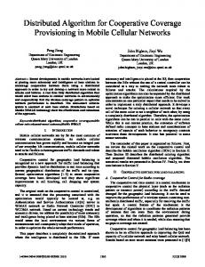
In this section, we are focusing on the assessment of the following functionalities, by using MATLAB simulation environment: a) compartments formation under various network topologies, and b) the triggering points for APs deactivation/re-activation under various network situations. In this analysis we consider a network area of twenty APs. The vertices of the graph depict the APs, while the links denote the one-hop away APs that each AP can sense (i.e. degree values). For instance, AP 5 can sense AP 7, while AP 7 is not in the transmission range of AP 5. On the other hand, APs 11 and 12 are within each other’s transmission range. Figure 5 shows the compartments that are formed using the algorithm, described in section III.B. In this test case the density of the depicted network area is 0.132 and four compartments have been formed. For the calculation of density, the local clustering coefficient for directed graphs has been used [7]. Node 2, node 6, node 8 and node 12 are the heads that have been elected for each compartment. The members of each compartment are distinguished in Figure 5, by the different colors of the graph nodes. For the specific compartment formation process advHops = 2 and mFactor= 2.
Figure 4. Compartment-assisted coverage optimization
area provides more opportunities for the re-activation of an AP (previously de-activated). The re-activation of an AP in a highdense network area of APs (if the capacity requirements do not require that), will increase further the overlapping of the selected channels and thus affecting the noise and the BER levels in the network area. If the CUR of the network compartment area has reached the level, which satisfies inequation (5), then the head proceeds to build the list of candidate APs for de-activation and selects the most appropriate. The list of the candidate nodes for de-activation includes those APs, where all associated UEs ( APUEs,i ) could be transferred to a neighboring AP ∈ Ae (i ) by satisfying all UECap, j requirements. Then, the head selects APm, with the minimum ratio: APCap,m
OFm
,
APCapAvail,m
where OFm is the overlapping factor between AP m and its one-hop away nodes; equation (4) is used for the calculation. In the case that the CUR level in the compartment has increased up to point that inequation (7) is satisfied then the process for APs re-activation is initiated. The Head of the compartment undertakes to identify if there is a de-activated AP that could be enabled in order to the serve the increasing capacity requirements. If more than one APs are available for re-activation, then the Head selects AP p, which one-hop away
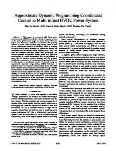
We have applied the compartments formation algorithm, for a network area that consists of 20 APs, and for different density levels (Figure 6). As the number of the edges among the APs increases, the number of formed compartments (and consequently elected Heads) tends to decrease. However, as Figure 6 presents, in some points an increase of the density level leads to an increase of the elected Heads, comparing to a previous state. The reason for this fluctuation is that the increase of density (more overlaps among APs transmissions) is not allocated uniformly in the whole network area, but in a specific locality. In some cases this may lead to the association of (previously) isolated parts of the network area (e.g., node 11 and node 9 possible association, Figure 5). Hence, according to the updated degree of each AP, more APs are elected as heads. This phenomenon justifies our design approach to avoid continuous re-organization of the formed compartments, since small changes in the overlapping of the APs may lead to large changes in the formed compartments. Thereinafter, we study the performance of the coverage optimization scheme, presented in section IV that the Head of each compartment executes. Specifically, we consider the compartment of Figure 5 that consists of 8 nodes with OF = 0.32 and diameter = 4. The head according to the overlapping factor between the constituent nodes identifies whether the COOP has reached the upper bound for checking the deactivation of an AP or the lower bound for checking available APs re-activation. As it is shown in Figure 7, in the specific
2259
compartments. Future work includes further experimentation, in order to study the impact of different compartment formation schemes as well as of additional optimization tasks. Formed Compartments
6 5 4 3 2 1
0.105 0.111 0.116 0.121 0.124 0.132 0.139 0.147 0.153 0.163 0.163 0.187 0.205 0.232 0.242 0.274 0.297 0.329 0.366 0.392 0.400
0
Network Area Density Level
Figure 5. A sample topology of access points and the formed compartments
Figure 6. Number of compartments for a network area of 20 APs
case (OF = 0.32) based on (5) and (7) inequations the upper bound for APs de-activation checking is triggered if the CUR = 0.05 (point where the ‘de-act UB’ line is crossed), while the lower bound for AP re-activation is triggered if CUR = 0.42 (point where the ‘re-act LB’ line is crossed). For the calculation of ‘de-act UB’ and ‘re-act LB’, the Head uses equations (6) and (8), and for the simulation we have set the Low Load and High Load thresholds at LL=0.25 and HL=0.7, respectively. With the increase of the overlapping factor of the specific compartment (OF=0.5, OF=0.8), which means that more APs are within each other’s transmission range, the required CUR for the de-activation or re-activation is also increasing. After an AP’s de-activation, the CUR of the respective compartment changes, since there is a decrease of the denominator of equation (2) i.e. compartment area available capacity. Hence, the updated COOP moves in the area between ‘re-actLB’ and ‘de-actUB’ lines. After an AP’s re-activation the CUR is reduced, considering that the used capacity remains static. From the above analysis it is obvious that in the case of a dense network area (as this is captured by the formed compartments), an AP de-activation process is triggered at higher load levels, comparing to the required load levels for a less dense network area. Furthermore, the behavior of the coverage optimization algorithm is affected by the structural characteristics of the formed compartments (e.g., size) and by the algorithm that has been selected for compartments formation. This observation leads us to update the re-actLB as well as the de-actUB, according to the structural characteristics of the formed compartment (e.g., diameter). The quality of the formed compartment is a key parameter for the success of the localized management action. VI.
1 0.9 0.8
In this work we have proposed the design of a dynamic logical topology (i.e. compartments) among cognitive network devices (i.e. APs) in order to identify optimization opportunities and control the physical topology (APs deactivation or re-activation). Specifically, we have proposed an algorithm for distributed compartments formation among APs and the algorithmic method for coverage optimization, by using the situation awareness of the heads of the established
OF = 0.8
COOP
0.6 0.5
OF = 0.5
OF = 0.32
0.4 de-act UB= 0.308
0.3 0.2 0.1
1
0.9
0.95
0.8
0.85
0.7
0.75
0.6
0.65
0.5
0.55
0.4
0.45
0.3
0.35
0.2
0.25
0.1
0.15
0.05
0
0
Capacity Usage Ratio (CUR)
Figure 7. COOP triggerring with respect to the CUR and OF values for a compartment of 8 APs
ACKNOWLEDGMENT This work is supported by the European Commission 7th Framework Programme through the Self-NET Project (http://www.ict-selfnet.eu).
REFERENCES [1] [2]
[3]
[4]
CONCLUSIONS
re-act LB = 0.758
0.7
[5]
[6]
[7]
2260
NGMN, “Recommendation on SON and O&M Requirements”, version 1.1, July 2008. D. Fagen, P.A. Vicharelli, J. Weitzen, "Automated Wireless Coverage Optimization With Controlled Overlap," Vehicular Technology, IEEE Transactions on , vol.57, no.4, pp.2395-2403, July 2008. L. Nagy, "Indoor Radio Network Optimization Using Multi Level Hierarchic Method," Wireless Communications and Networking Conference, 2009. WCNC 2009. IEEE , vol., no., pp.1-6, 5-8 April 2009 I. Haratcherev, M. Fiorito, C. Balageas, "Low-Power Sleep Mode and Out-Of-Band Wake-Up for Indoor Access Points," GLOBECOM Workshops, 2009 IEEE , vol., no., pp.1-6, Nov. 30 2009-Dec. 4 2009. A. Mihailovic, I. Chochliouros, A. Kousaridas, G. Nguengeng, et al. “Architectural Principles for Synergy of Self-management and Future Internet Evolution”, Proceeding of ICT Mobile Summit, June 2009. Yu, J.Y.; Chong, P.H.J.; , "A survey of clustering schemes for mobile ad hoc networks," Communications Surveys & Tutorials, IEEE , vol.7, no.1, pp. 32- 48, First Qtr. 2005. T. Schank and D. Wagner, Approximating clustering coefficient and transitivity, J. Graph Algorithms and Applications 9 (2005), 265-275.