Hindawi Security and Communication Networks Volume 2017, Article ID 4975302, 11 pages https://doi.org/10.1155/2017/4975302
Research Article Dynamic Rule Encryption for Mobile Payment Emir Husni School of Electrical Engineering & Informatics, Institut Teknologi Bandung, Jawa Barat, Indonesia Correspondence should be addressed to Emir Husni;
[email protected] Received 11 October 2016; Revised 8 December 2016; Accepted 18 December 2016; Published 26 January 2017 ´ Academic Editor: Angel Mart´ın Del Rey Copyright © 2017 Emir Husni. This is an open access article distributed under the Creative Commons Attribution License, which permits unrestricted use, distribution, and reproduction in any medium, provided the original work is properly cited. The trend of financial transactions by using a mobile phone or mobile payment increases. By using the mobile payment service, users can save money on mobile phone (handset) and separate from the pulse. For protecting users, mobile payment service providers must complete the mobile payment service with the transaction security. One way to provide transaction security is to utilize a secure mobile payment application. This research provides a safety feature used for an Android-based mobile payment application. This security feature is making encryption rules dynamically named Dynamic Rule Encryption (DRE). DRE has the ability to protect data by means of encrypting data with dynamic rules, and DRE also has a token function for an authentication. DRE token raised with dynamic time-based rules. Here, the time is used as a reference with the order of the day in the year (day of the year). The processes of the DRE’s encryption, decryption, and the DRE’s functionality as the token are discussed in this paper. Here, the Hamming distance metric is employed for having maximum differences between plaintext and ciphertext.
1. Introduction The current trend is numbers of mobile phones decreased slowly while smartphones are growing rapidly. In addition, the computing resources in smartphone improving yearly with more applications can be integrated into it. Due to applications, smartphone is an electronic device that is most commonly used. A sort of smartphone apps has been made by the developers in Indonesia, for example: GO-JEK (online taxi motorbike) has successfully run using smartphone [1], mobile-based academic information system [2], shopping using smartphone [3], mobile payment [4, 5], and mobile service commerce [6]. Trends in financial transactions using a mobile phone or mobile payment increase. The numbers of operators providing such services also increased. By employing the mobile payment service, customers can save money on mobile phone (handset) and separate from the main content. Thus, the mobile phone serves as an electronic wallet (mobile wallet). Currently, most of Android smartphones support Near Field Communication (NFC). The NFC has been implemented in shopping [3] and a mobile payment application [4, 5]. The mobile payment service provider should complete mobile payment service with a good transaction security. One path to provide transaction security is to utilize secure mobile
payment applications. Mobile payment applications should have good security because the application will contain sensitive data, including account, password, PIN, e-money, and transaction data. This research offers a security feature used for mobile payment applications on the Android operating system. This security feature is a dynamic encryption rule named Dynamic Rule Encryption (DRE). DRE has the power to protect information by encrypting data with dynamic rules, and DRE also has a function as a token for authentication. Token raised DRE using dynamic rules or change by time. The reference period used is on the order of the day in the year (day of the year). Many existing rules on DRE are limited to certain time. This causes the device to be connected to the server to update the rules DRE. By connecting to the server, the server can validate the existing data on the mobile payment application, so that if there are invalid data, the data is detected. In addition, the DRE token contains information about the device, time, mobile payment user’s account, and other information used for authentication.
2. Literature Survey 2.1. Encryption. One element that should be owned by the sensitive data is data security. Sensitive data should have
2
Security and Communication Networks
Plaintext
Encryption
To Graphi
Decryption
Plaintext
Plaintext 128
Key
Key
Figure 1: Encryption process.
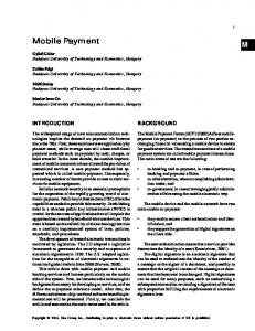
dependable data security; both when it is stored on storage media or when transferred to another location via any channel, for example, via the Internet. Data security can be constructed in various ways, one of which is by using encryption of the data to be stored or transferred. Encryption can also be named a secret password (cipher). But the actual encryption is only one part of a secret password. Secret password consists of encryption and decryption. Encryption is the procedure of encoding the information so that the information cannot be read by normal means. Encryption will change the data on the information that will be hard to read and time consuming if the encryption result data decoded without using any special rules or codes. Encryption involves secret data called key. The keys are also employed in the decryption process. Without using a key, the information will not be encrypted or decrypted. The information input into encryption called plaintext and encrypted data is called ciphertext. The ciphertext message contains all the information of the plaintext message but not in format that is obtained and read normally. Decryption process is required to restore the plaintext to ciphertext. The block diagram of encryption process is shown in Figure 1. 2.1.1. Encryption Type. By the type of the key, encryption is divided into two types, namely:
Round key (0)
128
XOR
SubBytes
ShiftRows For i = 1 to Nr − 1 MixColumns
128
Round key (i)
XOR
SubBytes
ShiftRows
Round key (Nr)
128
Final round
XOR Nr = number of rounds To Graphi
Figure 2: AES encryption process.
(1) Symmetric encryption, and (2) Asymmetric encryption. Symmetric encryption is encrypted using the same key for encryption and decryption, while the asymmetric encryption is encrypted using different keys for encryption and decryption, namely, a public key and a private key. Symmetric encryption includes AES, DES, and Triple DES. Asymmetric encryption includes RSA. Looking at ways of processing the data, there are two types of encryption, namely: (1) The stream cipher, and (2) Block cipher. Stream ciphers are used in the symmetric encryption, while the block ciphers are used in symmetric and asymmetric encryption. The difference between stream ciphers and block cipher is block ciphers process data in data blocks, while stream ciphers process data one bit or one byte at a time. 2.1.2. AES (Advanced Encryption Standard). AES is a type of encryption using symmetric keys and a block cipher [7]. AES consists of three types, namely, AES-128, AES-192, and AES256. Each has a size of 128-bit block cipher with a key size
of 128, 192, and 256 bits. AES has been analyzed extensively and is widely used throughout the world. From the size of the blocks, AES works on a 4 × 4 matrix in which each cell of the matrix consists of a 1 byte (8 bits); then the size of a block is 16 bytes. At AES, there are 4 main stages to process the incoming data, namely, stage SubBytes, ShiftRow, MixColumn, and add round key. Figure 2 illustrates the AES encryption process. 2.1.3. DES (Data Encryption Standard). DES is also a type of encryption using symmetric keys and a block cipher [8]. DES has a 64-bit block size. DES encrypts 64 bits of plaintext into 64 bits ciphertext using a 56-bit subkey generated from the master key of 64 bits. In the process of encryption and decryption, DES uses Feistel network. The DES encryption process is illustrated in Figure 3. 2.2. Token. The token is software or hardware used for authentication. Tokens are used to prove identity electronically as well as being used as electronic key to access something. Tokens can be used instead of the password security feature or used in conjunction with a password [9].
Security and Communication Networks
3
Input
Initial permutation
Input: plain-text (byte)
Pattern matrix
Substitution
Cyclic shift by rows and columns
Output: To Graphi text (byte)
Add round key
Matrix multiplication by constants
Transpose
Figure 4: Stages of algorithm. R0
L0
K1 +
f
R1 = L 0 ⊕ f(R0 , K1 )
L 1 = R0
K4 +
f
R4 = L 3 ⊕ f(R3 , K4 )
L 4 = R3
Inverse initial permutation
just as Connected Token, but, contactless tokens are not physically connected. One way contactless tokens connected to any device or computer is by using RFID. (4) Bluetooth Tokens. Bluetooth token is often combined with a USB token; that Bluetooth token can work either in a state connected or not connected physically to the device or a computer access point. Authentication using this token works when it is less than ten meters from the device or computer. When a Bluetooth mode does not work, then the token must be connected via USB. The advantage of using this token is the ability to sign-off from a certain distance (less than ten meters). (5) GSM Cellular Phone Token. GSM Cellular Phone token is GSM enabled mobile phone as a token. How to use this token is to install a token program (Java) on your phone. Another way is to use SMS, phone calls, and over Internet protocol (HTTP/HTTPS). There is a token called a mobile device token. Mobile device tokens are almost the same as GSM Cellular Phone tokens.
Output
3. Dynamic Rule Encryption Figure 3: DES encryption process.
2.2.1. Forms of Tokens. Tokens may take software or hardware. At hardware token, there is a chip. The chip has a function that varies from simple to complex. Tokens must have a certification indicating that the token meets various security standards, including meeting government security standards, industry security standards, testing standards, and other cryptographic standards. Here are some forms of token. (1) Disconnected Token. Disconnected Token has no connection to the access point device or computer. This token has display for displaying data or authentication serial numbers raised. That serial number will be filled in the field token (passcode) program interface, computer, or other device to be accessed. This token is one type of tokens most widely used. (2) Connected Token. Connected Token is a physical token which must be connected to the device or the computer to be accessed. This token will automatically authenticate when connected to any device or computer. The most common types of physical tokens are smart cards and USB tokens. (3) Contactless Token. Contactless token is almost the same as the Connected Token. Contactless token is connected to a device or computer access point. Contactless tokens are
Dynamic Rule Encryption (DRE) is a symmetric block cipher with a symmetrical key [10]. DRE cipher block size is 512 bits, while key length is 128 bits. On DRE there are 6 steps done in plaintext, namely: (1) Pattern matrix formation [11] (2) Substitution [12] (3) Cyclic shift by rows and columns [13] (4) Transpose [12] (5) The matrix multiplication by constants [12], and (6) Add round key [12] Substitution, cyclic shift, and transpose phases are functioned as confusion and diffusion. Confusion serves to establish the correlation between the ciphertext and the key when it is misplaced or not visible. Confusion is a nonlinear function [12]. Diffusion makes a correlation between the plaintext and ciphertext missing or not visible [12]. By using diffusion, the code will be difficult to resolve using statistical methods. In DRE, the sequence of steps may be changing over time. Figure 4 is one example of these stages. At other times, the sequence of steps turns out to be as in Figure 5. Step changes are explained in Figures 4 and 5 just as one example. DRE has a sequence pattern change. In addition, the
4
Security and Communication Networks
Input: plain-text (byte)
Pattern matrix
Output: To Graphi text (byte)
Add round key
Substitution
Transpose
Table 1: Substitution look-up table.
Cyclic shift by rows and columns Matrix multiplication by constants
Figure 5: Stages of algorithm with different pattern.
DRE has the elements or variables that may change on time, that is:
Nibble 1
(1) Placement pattern input of the matrix (2) The substituted matrix elements (3) The rows and columns shifted and amounts of shift operation (4) The constant matrix, and (5) The master key to add a round key stage 3.1. Encryption Process. Here is an explanation of the encryption process. (1) Matrix Pattern Formation. At this level, the DRE’s input will be separated into several parts and these parts will be combined with a pattern. The placement pattern of the matrix input is changing over time. Figures 6 and 7 provide an example of the matrix pattern change. Figure 6 shows one matrix pattern, in which the matrix is consisting of six parts with different colors. When the time changes, the matrix in Figure 6 will be turned into the matrix in Figure 7. As we can see that the matrix pattern is changed on time. (2) Substitution. At this stage, byte elements in a matrix are substituted with other values on look-up table. The number of elements in the matrix to be substituted is as much as 48 bytes elements. A byte substitution matrix element is determined by the bit pattern. Suppose bits in the byte matrix element are b7, b6, b5, b4, b3, b2, b1, and b0, where b0 = LSB and b7 = MSB. Couple substitutions are determined by changing the sequence of bits in a byte following the pattern of bits b7, b2, b3, b4, b5, b6, b1, and b0. Substitution of byte matrix elements is carried per nibble of the byte; that is, b7, b3, b5, and b1 are called nibble 1 and b2, b4, b6, and b0 are called nibble 2. Substitution is done by seeing the look-up table. Table 1 is a look-up table to nibble 1 (top) and to nibble 2 (bottom). Next in Table 2 there is an example of the substitution matrix element. (3) Cyclic Shift by Rows and Columns. At this stage, byte elements in the matrix will be shifted in rows or/and columns. Locations of rows and columns shifted and the amount of every shift can vary based on time. This shift can also be called a rotation. Here is an example of the cyclic shift for a 4 × 4 matrix. Equation (1) is an example of the cyclic in rows with the amount of shift shown in Table 3, while (2) is an example
Nibble 2
Input 0000 0001 0010 0011 0100 0101 0110 0111 1000 1001 1010 1011 1100 1101 1110 1111 0000 0001 0010 0011 0100 0101 0110 0111 1000 1001 1010 1011 1100 1101 1110 1111
Output 0111 1110 0100 1101 0001 0010 1111 1011 0011 1010 1000 0110 0101 1100 1001 0000 1101 1111 1100 1000 0010 0100 1001 0001 0111 0101 1011 0011 1110 1010 0000 0110
of the cyclic in columns with the amount of shift shown in Table 4. The Example of Row Cyclic Sliding 01100011 10100101 01000100 00001000 [ ] [00000000 01100100 00110100 10000100] [ ] [00101011 01011000 00100001 01011111] [ ] [00110000 00000101 11111100 00010011] ↓ 01100011 10100101 01000100 00001000 [ ] [01100100 00110100 10000100 00000000] [ ] [00100001 01011111 00101011 01011000] [ ] [00010011 00110000 00000101 11111100]
(1)
Security and Communication Networks
5 Table 2: Example of matrix element substitution. Pattern
Input
Nibble 2 (b7 b3 b5 b1)
Nibble 1 (b6 b2 b4 b0)
1100 0011 0010 1001
0001 1000 1101 0001
1000 1001 0110 0010 0110 0101 1000 0011 byte 0 [ [ byte 8 [ [ [ byte 16 [ [ [ byte 24 [ [ [ [ byte 32 [ [ [ byte 40 [ [ [ byte 48 [
byte 1 byte 9 byte 17 byte 25 byte 33 byte 41 byte 49
[ byte 56 byte 57
Output 1110 1110 1000 0011 1100 1100 0101 1110
byte 2 byte 3 byte 4 byte 5 byte 6 byte 7 ] byte 10 byte 11 byte 12 byte 13 byte 14 byte 15] ] ] byte 18 byte 19 byte 20 byte 21 byte 22 byte 23] ] ] byte 26 byte 27 byte 28 byte 29 byte 30 byte 31] ] ] ] byte 34 byte 35 byte 36 byte 37 byte 38 byte 39] ] ] byte 42 byte 43 byte 44 byte 45 byte 46 byte 47] ] ] byte 50 byte 51 byte 52 byte 53 byte 54 byte 55] ] byte 58 byte 59 byte 60 byte 61 byte 62 byte 63]
Figure 6: Matrix’s parts 1. Explanation: blue = SIM, green = IMEI, yellow = time stamp, gray = account number, orange = big transaction, and white = salt. byte 0 [ [ byte 8 [ [ [ byte 16 [ [ [ byte 24 [ [ [ [ byte 32 [ [ [ byte 40 [ [ [ byte 48 [ [ byte 56
byte 1 byte 9 byte 17 byte 25 byte 33 byte 41 byte 49 byte 57
byte 2 byte 3 byte 4 byte 5 byte 6 byte 7 ] byte 10 byte 11 byte 12 byte 13 byte 14 byte 15] ] ] byte 18 byte 19 byte 20 byte 21 byte 22 byte 23] ] ] byte 26 byte 27 byte 28 byte 29 byte 30 byte 31] ] ] ] byte 34 byte 35 byte 36 byte 37 byte 38 byte 39] ] ] byte 42 byte 43 byte 44 byte 45 byte 46 byte 47] ] ] byte 50 byte 51 byte 52 byte 53 byte 54 byte 55] ] byte 58 byte 59 byte 60 byte 61 byte 62 byte 63]
Figure 7: Matrix’s parts 2. Explanation: blue = SIM, green = IMEI, yellow = time stamp, gray = account number, orange = big transaction, and white = salt.
Table 3: The example of row cyclic shift. Row Number of cyclic shift to left
1 0
2 1
3 2
4 3
(4) Transpose. This stage is the matrix transpose operation. The transpose of a matrix is a new matrix whose rows are the columns of the original. Equation (3) is an example of the matrix transpose operation on a 4 × 4 matrix. The Example of Transpose on a 4 × 4 Matrix
The Example of Column Cyclic Sliding
byte 0 [ byte 4 [ [ [ byte 8 [byte 12
01100011 10100101 01000100 00001000 [ ] [01100100 00110100 10000100 00000000] [ ] [00100001 01011111 00101011 01011000] [ ]
01100011 00110100 00101011 11111100 [ ] [01100100 01011111 00000101 00001000] [ ] [00100001 00110000 01000100 00000000] [ ] [00010011 10100101 10000100 01011000]
byte 2 byte 6 byte 10 byte 14
byte 3 byte 7 ] ] ] byte 11] byte 15]
↓
[00010011 00110000 00000101 11111100] ↓
byte 1 byte 5 byte 9 byte 13
(2)
byte [byte [ [ [byte [ [byte
(3)
0 byte 4 byte 8 byte 12 1 byte 5 byte 9 byte 13] ] ] 2 byte 6 byte 10 byte 14] ] 3 byte 7 byte 11 byte 15]
(5) Matrix Multiplication by Constants. In this stage, the input matrix is multiplied by a constant element matrix. The matrix
6
Security and Communication Networks Table 4: The example of column cyclic shift.
Column Number of cyclic shift up
1 0
2 1
3 2
Secret key K
4 3 Reverse bits
elements are multiplied in nibble format. Matrix’s constants as multipliers can vary based on the time. Multiplication of matrices with a constant matrix is done in Galois field GF(24 ). Equation (4) is an example of one of the constants’ matrix in GF(24 ).
K1 XOR K2 L
R XOR
The Example of a Constant Matrix in GF(24 ) 3 [2 [ [ [2 [ [ [2 [ [ [2 [ [ [6 [ [5 [
4 5 6 2 2 2 2 3 4 5 6 2 2 2] ] ] 2 3 4 5 6 2 2] ] ] 2 2 3 4 5 6 2] ] ] 2 2 2 3 4 5 6] ] ] 2 2 2 2 3 4 5] ] 6 2 2 2 2 3 4] ]
Reverse bits
XOR
(4)
Kse1 = L mod C1, Kse2 = L mode C2
The M Matrix [ [105 [ [102 [ [ [101 [ [ [ 39 [ [115 [ [ [ 32 [ [ [ 98 [ [101 [ [ [ 97 [ [ [117 [ [116 [ [ [105 [ [ [102 [ [118 [
Figure 8: Master key expansion algorithm.
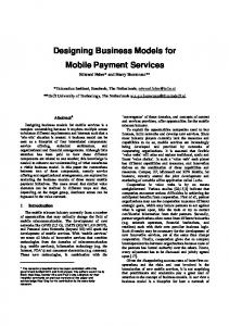
The master key expansion procedure is as follows. (1) Master key or hidden key, 𝐾, is transposed to gain 𝐾1 . (2) K 2 is obtained by performing xor operation between 𝐾 and 𝐾1 . (3) With the column, 𝐾2 is divided into two, namely, the right and the left. Both parts are made xor operation to gain 𝐾3 . (4) The right side and the left side of 𝐾2 are transposed. Both parts are then transposed. The results of operations are made xor operation to gain 𝐾4 .
78 ⋅ ⋅ ⋅ ⋅ ⋅ ⋅
] 106 107 ⋅ ⋅ ⋅ ⋅ ⋅ ⋅] ] 103 104 ⋅ ⋅ ⋅ ⋅ ⋅ ⋅] ] ] 102 103 ⋅ ⋅ ⋅ ⋅ ⋅ ⋅] ] ] 40 41 ⋅ ⋅ ⋅ ⋅ ⋅ ⋅] ] 116 117 ⋅ ⋅ ⋅ ⋅ ⋅ ⋅] ] ] 33 34 ⋅ ⋅ ⋅ ⋅ ⋅ ⋅] ] ] 99 100 ⋅ ⋅ ⋅ ⋅ ⋅ ⋅] ] 102 103 ⋅ ⋅ ⋅ ⋅ ⋅ ⋅] ] ] 98 99 ⋅ ⋅ ⋅ ⋅ ⋅ ⋅] ] ] 118 119 ⋅ ⋅ ⋅ ⋅ ⋅ ⋅] ] 117 118 ⋅ ⋅ ⋅ ⋅ ⋅ ⋅] ] ] 106 107 ⋅ ⋅ ⋅ ⋅ ⋅ ⋅] ] ] 103 104 ⋅ ⋅ ⋅ ⋅ ⋅ ⋅] ] 119 120 ⋅ ⋅ ⋅ ⋅ ⋅ ⋅] ] [108 109 110 ⋅ ⋅ ⋅ ⋅ ⋅ ⋅]
‖ K5 L = interger sum of byte K5
(6) Add Round Key. At add round key operation, a matrix element is combined with a block of the round key using bitwise xor. Round using 128-bits master key and master key will be expanded to produce a 512-bits subkey. When building a subkey, this process involves auxiliary matrix 𝑀 that contains the master key and iteration with a modulus of 255. Equation (5) is a matrix 𝑀 generated from the master keys 4C, 69, 66, 65, 27, 73, 20, 62, 65, 61, 75, 74, 69, 66, 75, and 6C,where Figure 8 is an algorithm to expand the master key of 128 bits into the 512-bit subkey.
77
Reverse bits
K4
[4 5 6 2 2 2 2 3]
76
K3
(5) K 3 and 𝐾4 are concatenated (united) to get 𝐾5 . (6) The byte integer value of 𝐾5 is summed to obtain 𝐿. (7) 𝐾se1 is calculated by the formula 𝐾se1 = 𝐿 mod C1, with 𝐶1 = 23.
(5)
(8) 𝐾se2 is calculated by the formula 𝐾se2 = 𝐿 mod C2, with 𝐶2 = 15. (9) Then, the subkey 𝐾s2 is obtained from the decrease of auxiliary matrix M as follows. (i) 𝐾s1 [row] [column] = M [row] [𝐾se1 + 𝐾se2 + column]. (ii) 𝐾s2 [row] [column] = M [row] [𝐾s1 [row] [column]]. (10) While, subkey 𝐾s1 is obtained from the decrease of auxiliary matrix M as follows.
Security and Communication Networks (i) 𝐾s1 [row] [column] = M [row] [𝐾s2 [row] [column]]. (ii) 𝑖th column of the matrix 𝐾s1 rotated vertically downwards as far as (((int (K[i]) mod 12) + 𝐾se1 ) mod 15). (iii) 𝑖th column of the matrix 𝐾s2 rotated vertically downwards as far as (((int (K[i]) mod 10) + 𝐾se1 ) mod 15).
7 In [14], the algorithm in Figure 8 can generate many changes on the subkey bits when little change occurs on the master key. 𝐾s1 and 𝐾s2 each subkey will generate 256 bits; then the total subkey generated is 512 pieces. Equation (6) is an example of some subkey generated from the master key 4C 69 66 65 27 73 20 62 65 61 75 74 69 66 75 6C. The Example of Some Subkey Produced by Master Key
6D 6A 49 40 6D 52 F2 49 40 3D 83 67 6E 34 3D 31 68 6F 35 3E 32 6E 6B 4A 41 6E 53 F3 4A 41 3E 84 3F 33 6F 6C 4B 42 6F 54 F4 4B 42 3F 85 69 70 36 34 70 6D 4C 43 70 55 F5 4C 43 40 86 6A 71 37 40 6E 4D 44 71 56 F6 4D 44 41 87 6B 72 38 41 35 71 39 42 36 72 6F 4E 45 72 57 F7 4E 45 42 88 6C 73
(6)
74 3A 43 37 73 70 4F 46 73 58 F8 4F 46 43 69 6D 50 47 74 59 F9 50 47 44 8A 6E 75 3B 44 38 74 71 39 75 72 51 48 75 5A FA 51 48 45 8B 6F 76 3C 45 49 76 5B FB 52 49 46 8C 70 77 3D 46 3A 76 73 52
After the plaintext experiences the 6 steps above, the plaintext will change into the ciphertext. 3.2. Process Description. Here is an explanation of the process on the description. (1) Inverse Substitution. This stage is the reverse of substitution. Inverse substitution is done using an inverse substitution table. The rules for determining the inverse substitution couple equally with the existing rules at the stage of encryption substitution. The byte substitution matrix element is done by looking at the inverse substitution look-up table as shown in Table 5. (2) Inverse Cyclic Shift by Rows and Columns. This stage is the contrary of the cyclic shift by row and column in the encoding process. The magnitude and direction of the shift are the opposite shift in the encryption process. (3) Inverse Matrix Multiplication by Constants. This stage is the inverse of a matrix multiplication by constants in the encryption process. Inverse multiplication of matrices with constant matrix is done in GF(24 ). (4) Inverse Transpose. Inverse transpose is equal to the inverse transpose. To return to the original state matrix, transpose is performed again. (5) Inverse Adds Round Key. This stage is the reverse of the process add a round key at the stage of encryption. Matrix elements will do the same xor operation as it exists at this
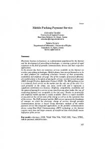
stage but with the encryption subkey inverted schedule order. The process of getting a subkey of the master key is equal to the encryption stage. Later on, the ciphertext goes through the five stages of decryption changing into plaintext and the resulting data can be used by the mobile payment application. The number of decryption stages is less than encryption stages because at the decryption there is no matrix pattern formation. After decryption is performed, the mobile payment application can retrieve the desired data on the location of the data stored in a matrix pattern. 3.3. DRE as a Token. The purpose DRE made was to secure the data exchanged during payment transactions using mobile applications. In mobile payment applications, in addition to serving as a DRE encryption algorithm that encrypts data, DRE also serves as a token. The token will ensure the transaction is valid from the start until the final stage of the transaction. With the token function, DRE is suitable for use in mobile payment applications that have an offline transaction mode because the offline transactions are highly susceptible to fraud (transactions with a prosthetic device/not registered), the transfer of the counterpart (man in the middle), or other attacks. On a generated token there is information about the user’s device, including IMEI and IMSI. In addition, there are also time information, user accounts, transaction data, and other information if needed. DRE rules used to generate tokens change on time. The rules are stored in a DRE database. In this research, a time frame utilized to bring forth the token is
8
Security and Communication Networks Table 5: Inverse substitution look-up table.
Nibble 1
Nibble 2
Input 0000 0001 0010 0011 0100 0101 0110 0111 1000 1001 1010 1011 1100 1101 1110 1111 0000 0001 0010 0011 0100 0101 0110 0111 1000 1001 1010 1011 1100 1101 1110 1111
Output 1111 0100 0101 1000 0010 1100 1011 0000 1010 1110 1001 0111 1101 0011 0001 0110 1110 0111 0100 1011 0101 1001 1111 1000 0011 0110 1101 1010 0010 0000 1100 0001
based along the order of the day in the year (day of the year). Figure 9 illustrates a block diagram of DRE as a token. Security or authentication process performed by DRE on payment transactions using mobile applications is as follows. (1) When a transaction starts, the two devices that will make transactions generate tokens. (2) Tokens are then exchanged between the payer and the merchant (beneficiary paid). At the time of the exchange of data, in addition to the token sent, the device information including IMEI and IMSI is also sent unencrypted. (3) Each device will check the given token by decrypting it using the existing rules on the DRE data base, in mobile payment applications. The merchant’s token will be decrypted on the payer’s device so that the
Key: time information
IMEI and other information
DRE
Token
Figure 9: Token generator.
payer will acquire the IMEI and IMSI of the merchant’s device, as well as other data. The payer’s token will be decrypted on the merchant’s device, so that the payer will acquire the IMEI and IMSI of the payer’s device, as well as other data. (4) IMEI and IMSI following the token decryption will be compared with the IMEI and IMSI sent in an unencrypted format (plaintext). If the IMEI and IMSI of the decrypted result are the same with IMEI and IMSI sent in plaintext format, so, the counterpart device is valid for transactions. The token will always exchange during transmission of data between the two devices. Thus, fraud by third-party devices can be prevented when the transaction takes place.
4. Implementation and Testing 4.1. Implementation. Distance (Hamming distance) is numbers of different bits between two words (here is between two code words). The largest distance can be achieved between two code words is half of the total length of a code word. Here, the distance metric is employed for making maximum differences between a plaintext and a ciphertext. The maximum difference is half of the length of the plaintext because 100% difference in binary means the same as the plaintext (converting all bits). To produce ciphertext which has a distance approaching half the length of the plaintext, the election rules are required. This is also done so that the encryption and decryption process is working well. The rules are generated by the pattern generator. The pattern generator selects at random pattern by using a random function with various rules given. Here are the rules chosen randomly. (1) Placement pattern input of the matrix (2) The substituted matrix elements (3) The rows and columns shifted and amounts of shift operation (4) The constant matrix, and (5) The master key to add a round key stage Placement of input (plaintext) was randomly selected from the possibilities. There are no criteria for the selection of rules specifically for this stage. For cyclic shift, selected
Security and Communication Networks
9
Table 6: Distance comparison between with and without random function. Number 1
Distance between input and output Rule selection without Rule selection with random function random function 271
243
2
265
252
3
267
264
4
267
236
5
279
237
6
280
254
7
272
264
8
270
264
9
272
259
10 Average
273
261
271.6
253.4
range scale is of 0–7 with a random shift. Rows or columns shifted are selected randomly from all the possibilities. For matrix multiplication by a constant, the constant is selected from the variety of 1–15. Constants may not be 0 to be decrypted. Constants also must not be worth more than 15 to be multiplied in GF(24 ). The rule selection with and without random function will result in differences in distance between the input and output; the way this election may affect the performance of the DRE. Table 6 shows 10 data comparisons between the input and output as a result of the rule selection with and without the random function. The data used is 512 bits. It is shown in Table 6 that by using a random function, the resulting distance will tend to close half of the length of the input, which will be close to 256 bits. This is because by using a random function, the rule option will be chosen evenly, or in other words, is not prone to certain rules option. With the prevalence of the rule option selected, the resulting combination of rules will have a good variety so that the resulting distance will be close to the best value. Researches of Hamming distance computation on encryption have been done in [15–17]. Here, the DRE is employed in resulting maximum Hamming distance. 4.2. Distance Testing. DRE testing in this study is conducted by conducting five hundred times of testing. In each test, the data being input is different. One type of input data is the time stamp. Time stamp taken as input is a time stamp with a difference every thirty seconds. An accumulated time stamp is a time stamp accumulation every thirty seconds, while the nonaccumulated time stamp is a time stamp difference with thirty seconds earlier. Table 7 gives the results of DRE distance testing. The input of DRE in these experiments is the data (code word) with a size of 512 bits (including salt), then the best
distance between input and output code words is 256 bits. By appearing at the above test results, it can be concluded DRE has a proficient protection. In the entire operation or phase, DRE operation can produce an average distance between input and output code words of around 256 bits. The distance testing between the output and other output code words with a slight difference in its input can also reflect the level of the strength of a cipher. If the distance among the outputs approaching half the length code word, then the results of encryption code word have different configuration of the better code word. In the entire operation, DRE can produce an average distance among the outputs of about 258 bits. The operation or stage in the encryption process that provides most difference both in code word is the substitution operation. The substitution operation average distance is approximately 262 bits. 4.3. Time Testing. Time testing can represent the weight of a cipher algorithm run on a device or operating system. Here are the results of time testing for encryption and decryption. Tests are conducted as much as one thousand times using a Google Nexus S smartphone. A Sony Xperia SK17i smartphone is also used in this test which serves as a comparison. Table 8 is the result of time testing. Judging from the results, it can be concluded that the DRE is not heavy or burdensome if run on mobile devices including smartphones. This is reinforced by the results of comparative testing using the device Sony Xperia SK17i. By using Sony Xperia SK17i, DRE encryption and decryption only takes about 18 ms. The test results are also compared with the time of Advanced Encryption Standard (AES) encryption [18]. Both tests are using the Google Nexus S for one thousand times. Table 9 gives the results of comparative testing time between DRE and AES. When compared with the speed of AES, DRE is much slower. By using the Google Nexus S, the time required to perform AES encryption is 0.62 ms, while the time required to decrypt AES is 1.15 ms. The cause DRE is lagging behind the AES in speed is due to the AES function being designed in the native (C/C++) programming language, so it can perform faster in memory access and integer and floating-point calculations. Here, DRE process is designed and implemented using Android programming language [19, 20].
5. Conclusion Dynamic Rule Encryption (DRE) algorithm is designed as a security element of a mobile payment application. In this paper, DRE serves to secure sensitive data as well as the authentication token when trading. From the distance tests performed in this study, DRE has a good level of security because the average Hamming distance between the input and the output code words is about half of the length of the data being input. Thus, it will not be easy to trace the plaintext from the ciphertext. From the time of testing result, it is found that DRE is lightly used on mobile
10
Security and Communication Networks Table 7: Result of distance testing.
Testing
Average of the distance to the input
Average of the distance to the previous output
253.016
244.84
253.016
257.55
262.064 96.108 179.196 191.454 164.148 227.656
175.73 120.014 169.136 123.558 143.326 156.298
Using all stages (per 30 seconds) Using all stages (add per 30 seconds accumulation) Substitution stage The row cyclic sliding stage The column cyclic sliding stage Transpose stage Multiplying stage in GF(24 ) Add round key stage
Table 8: Results of time testing. Device
Time average of encryption (ms)
Time average of decryption (ms)
19.537 18.262
23.519 18.428
Google Nexus S Xperia SK17 i
[5]
Table 9: Time average of DRE and AES. Cipher
Time average of encryption Time average of decryption (ms) (ms)
DRE AES
19.537 0.62
[6]
23.519 1.147 [7]
devices because it has a fair execution time, not less than 24 ms. [8]
Competing Interests The author declares that he has no competing interests.
[9]
References [1] F. A. W. Wirawan and E. Oktivera, “Analysis on the implementation of digital marketing towards motorbike transport service case study: GO-JEK (online taxi motorbike) Jakarta, Indonesia,” in Proceedings of the 2nd International Conference on Information Technology Systems and Innovation (ICITSI ’15), pp. 1–6, Bandung-Bali, Indonesia, November 2015. [2] S. Budi and H. T. Sukmana, “Developing mobile-based academic information system: a case study at Islamic State University (UIN) Syarif Hidayatullah Jakarta,” in Proceedings of the 4th International Conference on Cyber and IT Service Management, Bandung, Indonesia, April 2016. [3] E. Husni and S. Purwantoro, “Shopping application system with Near Field Communication (NFC) based on Android,” in Proceedings of the International Conference on System Engineering and Technology (ICSET ’12), pp. 1–6, IEEE, Bandung, Indonesia, September 2012. [4] E. Husni and A. Ariono, “Development of integrated mobile money system using Near Field Communication (NFC): smartphone and electronic data capture,” in Proceedings of the 8th International Conference on Telecommunication Systems Services
[10]
[11]
[12]
[13]
[14]
and Applications (TSSA ’14), pp. 1–6, IEEE, Bali, Indonesia, October 2014. E. Husni, Kuspriyanto, N. Basjaruddin, T. Purboyo, S. Purwantoro, and H. Ubaya, “Efficient tag-to-tag Near Field Communication (NFC) protocol for secure mobile payment,” in Proceedings of the International Conference on Instrumentation, Communication, Information Technology and Biomedical Engineering (ICICI-BME ’11), pp. 97–101, Bandung, Indonesia, November 2011. E. Husni, B. Leksono, and M. R. Rosa, “Digital signature for contract signing in service commerce,” in Proceedings of the International Conference on Technology, Informatics, Management, Engineering and Environment (TIME-E ’15), pp. 111–116, IEEE, Samosir, Indonesia, September 2015. A. J. Elbirt, W. Yip, B. Chetwynd, and C. Paar, “An FPGA-based performance evaluation of the AES block cipher candidate algorithm finalists,” IEEE Transactions on Very Large Scale Integration (VLSI) Systems, vol. 9, no. 4, pp. 545–557, 2001. W. F. Ehrsam, S. M. Matyas, C. H. Meyer, and W. L. Tuchman, “A cryptographic key management scheme for implementing the Data Encryption Standard,” IBM Systems Journal, vol. 17, no. 2, pp. 106–125, 1978. H. B. Kazemian and L. Meng, “Neuro-fuzzy control for MPEG video transmission over bluetooth,” IEEE Transactions on Systems, Man and Cybernetics Part C: Applications and Reviews, vol. 36, no. 6, pp. 761–771, 2006. J. Daemen and V. Rijmen, “The first 10 years of advanced encryption,” IEEE Security and Privacy, vol. 8, no. 6, pp. 72–74, 2010. Y. Tang and L. Zhang, “Adaptive bucket formation in encrypted databases,” in Proceedings of the IEEE International Conference on e-Technology, e-Commerce and e-Service (EEE-05 ’05), pp. 116–119, Hong Kong, China, March-April 2005. N. Ben Hadjy Youssef, W. El Hadj Youssef, M. Machhout, R. Tourki, and K. Torki, “Instruction set extensions of AES algorithms for 32-bit processors,” in Proceedings of the 48th Annual IEEE International Carnahan Conference on Security Technology (ICCST ’14), pp. 1–5, Rome, Italy, October 2014. Z. Guosheng and W. Jian, “Security analysis and enhanced design of a dynamic block cipher,” China Communications, vol. 13, no. 1, pp. 150–160, 2016. A. J. Paul, P. Mythili, and J. K. Paulus, “Matrix based key generation to enhance key avalanche in advance encryption standard,” in Proceedings of the International Conference on VLSI, Communication & Instrumentation, pp. 31–34, Kottayam, India, April 2011.
Security and Communication Networks [15] A. Jarrous and B. Pinkas, “Secure computation of functionalities based on Hamming distance and its application to computing document similarity,” International Journal of Applied Cryptography, vol. 3, no. 1, pp. 21–46, 2013. [16] J. Bringer, H. Chabanne, and A. Patey, “SHADE: Secure HAmming DistancE computation from oblivious transfer,” in Financial Cryptography and Data Security, vol. 7862 of Lecture Notes in Computer Science, pp. 164–176, Springer, Berlin, Germany, 2013. [17] F. Guo, W. Susilo, and Y. Mu, “Distance-based encryption: how to embed fuzziness in biometric-based encryption,” IEEE Transactions on Information Forensics and Security, vol. 11, no. 2, pp. 247–257, 2016. [18] Lara-Ni˜no, C. Andr´es, M.-S. Miguel, and D.-P. Arturo, “An evaluation of AES and present ciphers for lightweight cryptography on smartphones,” in Proceedings of the 26th International Conference on Electronics, Communications and Computers (CONIELECOMP ’16), pp. 87–93, Cholula, Mexico, February 2016. [19] J. K. Lee and J. Y. Lee, “Android programming techniques for improving performance,” in Proceedings of the 3rd International Conference on Awareness Science and Technology (iCAST ’11), pp. 386–389, IEEE, Dalian, China, September 2011. [20] Y. Kwon, S. Lee, H. Yi et al., “Mantis: efficient predictions of execution time, energy usage, memory usage and network usage on smart mobile devices,” IEEE Transactions on Mobile Computing, vol. 14, no. 10, pp. 2059–2072, 2015.
11
International Journal of
Rotating Machinery
Engineering Journal of
Hindawi Publishing Corporation http://www.hindawi.com
Volume 2014
The Scientific World Journal Hindawi Publishing Corporation http://www.hindawi.com
Volume 2014
International Journal of
Distributed Sensor Networks
Journal of
Sensors Hindawi Publishing Corporation http://www.hindawi.com
Volume 2014
Hindawi Publishing Corporation http://www.hindawi.com
Volume 2014
Hindawi Publishing Corporation http://www.hindawi.com
Volume 2014
Journal of
Control Science and Engineering
Advances in
Civil Engineering Hindawi Publishing Corporation http://www.hindawi.com
Hindawi Publishing Corporation http://www.hindawi.com
Volume 2014
Volume 2014
Submit your manuscripts at https://www.hindawi.com Journal of
Journal of
Electrical and Computer Engineering
Robotics Hindawi Publishing Corporation http://www.hindawi.com
Hindawi Publishing Corporation http://www.hindawi.com
Volume 2014
Volume 2014
VLSI Design Advances in OptoElectronics
International Journal of
Navigation and Observation Hindawi Publishing Corporation http://www.hindawi.com
Volume 2014
Hindawi Publishing Corporation http://www.hindawi.com
Hindawi Publishing Corporation http://www.hindawi.com
Chemical Engineering Hindawi Publishing Corporation http://www.hindawi.com
Volume 2014
Volume 2014
Active and Passive Electronic Components
Antennas and Propagation Hindawi Publishing Corporation http://www.hindawi.com
Aerospace Engineering
Hindawi Publishing Corporation http://www.hindawi.com
Volume 2014
Hindawi Publishing Corporation http://www.hindawi.com
Volume 2014
Volume 2014
International Journal of
International Journal of
International Journal of
Modelling & Simulation in Engineering
Volume 2014
Hindawi Publishing Corporation http://www.hindawi.com
Volume 2014
Shock and Vibration Hindawi Publishing Corporation http://www.hindawi.com
Volume 2014
Advances in
Acoustics and Vibration Hindawi Publishing Corporation http://www.hindawi.com
Volume 2014