parent virtual network embedding (VNE), Optical orthogonal frequency-division ..... [7] Y. Wang et al., âVirtual optical network services across multiple domains.
IEEE ICC 2013 - Next-Generation Networking Symposium
Dynamic Transparent Virtual Network Embedding over Elastic Optical Infrastructures 1
Long Gong1 , Wenwen Zhao1 , Yonggang Wen2 , Zuqing Zhu1,† School of Information Science and Technology, University of Science and Technology of China, Hefei, China 2 School of Computer Engineering, Nanyang Technological University, Singapore † Email: {zqzhu}@ieee.org
Abstract—We propose a novel dynamic transparent virtual network embedding (VNE) algorithm, which considers node mapping and link mapping jointly, for network virtualization over optical orthogonal frequency-division multiplexing (O-OFDM) based elastic optical infrastructures. For each virtual optical network (VON) request, the algorithm first transfers the substrate optical network into a layered-auxiliary-graph according to the spectrum usage of each fiber link, then applies a node mapping approach that considers the local information of all substrate nodes, and accomplishes the link mapping, in a single layer of the auxiliary graph. The simulation results verify that the proposed algorithm considers the uniqueness of O-OFDM networks and outperforms two reference algorithms that directly apply the VNE schemes developed for Layer 2/3 or WDM network virtualization, by providing lower VON blocking probability. The simulations with a realistic topology also demonstrate that the average lengths of embedded substrate paths are wellcontrolled within the typical transmission reaches of O-OFDM signals. To the best of our knowledge, this is the first proposal that includes both link mapping and node mapping to address dynamic transparent VNE over elastic optical infrastructures. Index Terms—Optical network virtualization, Dynamic transparent virtual network embedding (VNE), Optical orthogonal frequency-division multiplexing (O-OFDM)
I. I NTRODUCTION The recent booming of network-based applications has stimulated research and development for highly elastic and scalable networking technologies. As a result, network virtualization is emerging as a promising solution for future Internet and starts to attract more and more research interests [1]. Meanwhile, thanks to the numerous bandwidth of optical fiber, network operators have been relying on fiber-optic technologies to scale their networks with the exponentially rising trend of bandwidth demands. For physical data transmission in optical networks, the optical orthogonal frequency-division multiplexing (OOFDM) technology is recently considered as a powerful substitute for wavelength-division multiplexing (WDM), due to its elastic nature [2]. In O-OFDM based networks, the spectral resource is allocated based on contiguous subcarrier frequency slots with bandwidths at a few GHz or even narrower. Hence, a bandwidth-variable O-OFDM transponder can assign justenough numbers of subcarrier slots to serve the connection requests, and achieves sub-wavelength granularity. To this end, O-OFDM based elastic optical networks are considered as potential physical infrastructures for network virtualization [3, 4], especially for highly-distributed and data-intensive applications such as petabits-scale grid computing [5].
978-1-4673-3122-7/13/$31.00 ©2013 IEEE
Optical network virtualization is to provision multiple virtual optical networks (VONs) over a substrate (or physical) optical network for sharing the computing, switching and bandwidth resources [3, 6]. VONs consist of virtual nodes (VNs) and virtual optical links (VOLs) that connect them. An infrastructure provider serves VONs using a procedure called virtual network embedding (VNE), which allocates necessary resources in the substrate network to every VON request through node mapping and link mapping. Typically, we can categorize VNE into static and dynamic schemes. For static VNE, all VON requests are known a priori, and the infrastructure provider can optimize the order of requestserving to improve the efficiency of substrate resource utilization. Dynamic VNE considers how to serve time-variant VON requests in a dynamic network environment. Since the VON requests are not known any more and can come in and leave on-the-fly, dynamic VNE needs more sophisticated algorithms to minimize the blocking probability of VON requests. Most of the previous works on VNE over optical networks were targeted for infrastructures using either time-division multiplexing (TDM) (e.g., SONET or SDH) [7], or WDM [8–11]. In [7], Wang et al. investigated dynamic VNE over multiple-domain SDH networks and proposed a scheduling scheme for serving VON requests efficiently. Based on the assumption that all substrate nodes are equipped with sufficient wavelength converters, a mixed integer linear programming (MILP) model was formulated and solved in [8] for static VNE over WDM networks. By taking the physical layer impairments (PLIs) into account, Peng et al. proposed a dynamic impairment-aware VNE algorithm for WDM networks in [9]. They then extended those works in [10] to consider both single-line-rate and mixed-line-rate WDM networks. In [11], Pages et al. formulated integer linear programming (ILP) models for transparent and opaque VNE over WDM networks, and proposed a heuristic for the transparent scheme. Notice that since they did not address node mapping of VONs, the works in [9–11] only solved the VNE problem partially. Network virtualization over elastic optical infrastructures based on O-OFDM only starts to attract research interests since recently. Its operation principles and key enabling technologies were reviewed in [3, 4]. These reviews pointed out that the operation of O-OFDM transponders requires a VOL to run over subcarrier slots that are contiguous in the spectrum domain. Therefore, there are additional constraints for VNE
3466
over O-OFDM networks, and the algorithms developed for WDM or Layer 2/3 network virtualizations are not directly applicable. Pages et al. formulated an ILP model for static opaque VNE over O-OFDM networks in [12]. However, VON node mapping was still omitted. In this paper, we consider O-OFDM networks with timevariant VON requests, and propose a dynamic transparent VNE algorithm that includes both link mapping and node mapping. Similar to the situation of the link mapping in transparent VNE over WDM networks [11], we need to assign the same set of subcarrier slots to every VOL in a VON, to make sure that optically transparent end-to-end connections can be set up between any two VNs in the VON. For each VON request, the proposed algorithm first transfers the substrate optical network into a layered-auxiliary-graph according to the spectrum usage of each fiber link, then applies a novel node mapping approach that considers the local information of all substrate nodes, and accomplishes the link mapping by performing shortest-path routing, in a single layer of the auxiliary graph. To the best of our knowledge, this is the first proposal that includes both link mapping and node mapping to address dynamic transparent VNE over elastic optical infrastructures. The rest of the paper is organized as follows. Section II formulates the problem of dynamic transparent VNE over elastic optical infrastructures. The design of the proposed VNE algorithm is discussed in Section III. Section IV shows the simulation results for performance evaluations. Finally, Section V summarizes the paper.
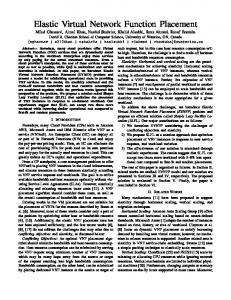
Fig. 1.
An example of transparent VNE.
B. VNE Procedures When a VON request arrives, a dynamic transparent VNE algorithm tries to perform two operations: 1) Assign the VNs to substrate nodes that have enough computing resources (i.e., node mapping), and 2) Select substrate fiber links to realize the VOLs and allocate enough subcarrier slots on the selected ones to satisfy the bandwidth requirements (i.e., link mapping). If both operations are successful, the VON request is provisioned; otherwise, it is blocked. The details of node mapping and link mapping are given below. 1) Node Mapping: Each VN v r ∈ V r is mapped onto an unique substrate node v s ∈ V s . Mathematically, it can be described as a one-to-one mapping, MN , such that, MN (v r ) = v s ,
vr ∈ V r , vs ∈ V s
(1)
under the following two constraints, • One-to-one mapping constraint
II. P ROBLEM F ORMULATION
MN (v r,1 ) = MN (v r,2 ),
A. VNE Models 1) Substrate Optical Network: A substrate optical network can be modeled as an undirected graph, denoted as Gs (V s , E s ), where V s is the set of substrate nodes and E s is the set of substrate fiber links. Each node v s ∈ V s associates with an available computing capacity csvs , i.e., the node’s computing power. For each link es ∈ E s , we define a bit-mask bses that contains B bits, where B is the maximum number of subcarrier slots that a fiber link can accommodate. When bses [j] = 1, the j-th slot on link es is occupied, otherwise bses [j] = 0. Fig. 1(a) shows an illustrative example of a substrate network, where the computing capacities of substrate nodes are labeled in the rectangles and the bit-mask on each fiber link depicts its spectrum usage. 2) VON Requests: A VON request can also be modeled as an undirected graph Gr (V r , E r ). We use notation crvr to denote the computing capacity requirement of each VN v r ∈ V r in the VON request. The bandwidth requirement of each VOL er ∈ E r is defined as nr , which is the number of contiguous slots we need to allocate for it. Fig. 1(b) shows a VON request, where the computing capacity requirements are labeled similarly as in Fig. 1(a) and the number on each VOL denotes the bandwidth requirement nr . Notice that nr is identical for all VOLs in a VON, which is the common case for a symmetric network.
•
∀v r,1 , v r,2 ∈ V r
if and only if v r,1 = v r,2 . Substrate computing capacity constraint crvr ≤ csvs
For example, as shown in Fig. 1(c), the node mapping for the VON request in Fig. 1(b) is {a → D, b → B, c → E}. 2) Link Mapping: Similar to the routing and spectrum assignment (RSA) problem described in [13], link mapping needs to decide how to embed each VOL onto the substrate paths and how to assign certain number of contiguous slots under the spectrum assignment constraints. Notice that in transparent VNE, we need to assign the same set of subcarrier slots to every VOL in a VON. We use notation P s to denote the set of acyclic paths in Gs , and define a bit-mask br that contains B bits to represent the spectrum allocations. When br [j] = 1, the j-th slot is allocated, otherwise, br [j] = 0. Then, the link mapping can be described as ML , such that, ML (er ) = ps ,
e r ∈ E r , ps ∈ P s
under the following three constraints, 1 • Bandwidth requirement constraint
3467
sum(br ) = nr 1 Note
that the allocated slots must be contiguous.
(2)
•
Substrate bandwidth capacity constraint � � B − sum( bses ) ≥ nr
Algorithm 1: VNE-LINM-LAGLM Algorithm input : Substrate network Gs , a VON request Gr output: Node mapping MN , link mapping ML
er ∈E r es ∈ps
•
1
Spectrum non-overlapping constraint � � bses )) = 0 sum(br ∩ ( er ∈E r
2 3 4
es ∈ps
� where sum(·) adds all bits in a bit-mask together, is the bit OR operator for multiple bit-masks, and ∩ operates bit AND for two bit-masks. In Fig. 1(c), the link mapping is {(a, b) → (D, B), (a, c) → (D, E)}, with the allocated slots highlighted.
5 6 7 8 9 10
C. VNE Objective
11 12
The objective of a dynamic transparent VNE algorithm is to minimize the blocking probability of VON requests, which is defined as the number of blocked requests over the number of arrived ones during certain time period. Actually, there are two penalty factors that can deteriorate the blocking performance. 1) Penalty I: The mapped substrate nodes or links do not have enough resources. 2) Penalty II: The mapped substrate nodes and links have enough resources, but the available slots on mapped links can not satisfy the spectrum assignment constraints. These two penalties can guide us for designing highly-efficient dynamic transparent VNE algorithms.
13 14 15 16 17 18
19 20 21 22 23 24
III. DYNAMIC T RANSPARENT VNE A LGORITHM
25
In this section, we propose an efficient algorithm to solve the problem of dynamic transparent VNE over elastic optical infrastructures. To alleviate Penalty I, we design a greedy node mapping to consider the local information of all substrate nodes. While to mitigate Penalty II, we apply a layeredauxiliary-graph approach to optimize link mapping under the spectrum assignment constraints. We denote this proposed algorithm as VNE-LINM-LAGLM, which is the abbreviation for “VNE with local information based node mapping and layered-auxiliary-graph based link mapping”. Algorithm 1 illustrates the overall procedures of VNE-LINM-LAGLM, where node(·) returns the number of nodes in a graph and |·| returns the number of elements in a set. A. Layered Auxiliary Graph In Algorithm 1, Lines 2-18 depict the procedures of how to transfer the substrate network into a layer of the auxiliary graph. Specifically, the algorithm checks whether a block of nr contiguous slots is available on every fiber link. If yes, the link is inserted into the i-th layer of the auxiliary graph, where i is the starting-index of the subcarrier slot. After checking all fiber links, the algorithm searches for connected components in the constructed layer, and sorts them according to the number of nodes they have. A connected component is a sub-graph in which any two nodes are connected by paths, and which is connected to no additional nodes in the super-graph [14].
26 27 28 29 30
backup Gs in Gst ; for i = 1 to B − nr + 1 do restore Gs to Gst ; // start with Gs to construct the i-th layer foreach es ∈ E s in Gs do if sum(bses [i...(i + nr − 1)]) > 0 then cut link es in Gs ; end end k = 1; foreach connected component in Gs do Gsub ← select a connected component of Gs ; k remove Gsub from Gs ; k sub if node(Gk ) ≥ |V r | then k = k + 1; end end sub sort {Gsub j , j = 1...k − 1} based on node(Gj ) in descending order; for j = 1 to k − 1 do apply Algorithm 2 to embed Gr onto Gsub j ; if embedding is successful then provision Gr ; restore Gs to Gst ; update Gs accordingly; output MN , ML and stop; end end end mark Gr as blocked; restore Gs to Gst ;
B. Node Mapping and Link Mapping Algorithms 2 illustrates the detailed procedures of node mapping and link mapping in the constructed layer of the auxiliary graph. The local information of a substrate node v s considers its available computing capacity csvs and node degree dsvs . Notice that the node degree dsvs is derived from a single layer of the constructed layered graph, but not from the original substrate network. We define the local information of a substrate node on the i-th layer as hsvs = csvs dsvs dsvs
(3) s
denotes the node degree of node v in the i-th layer Where of the constructed layered graph. Intuitively, a larger value of hsvs means that the node v s has a bigger embedding potential. IV. P ERFORMANCE E VALUATIONS A. Simulation Setup We evaluate the proposed VNE-LINM-LAGLM algorithm with simulations that use two substrate network topologies, a
3468
local information with the same method of the first one, but constructs the layered-auxiliary-graph for the link mapping. We name it as “VNE reference with layered link mapping”, or VNE-REF-LLM. VNE-REF-LLM mimics the situation that we consider the uniqueness of O-OFDM physical layer in the link mapping stage, but still directly apply the node mapping scheme developed for Layer 2/3 network virtualization.
Algorithm 2: Node Mapping and Link Mapping r input : Gsub k , G output: MN , ML , VNE status F 1 2 3 4 5 6 7 8 9 10 11 12 13 14 15 16 17 18 19 20 21
compute local information hsvs for all v s in Gsub k ; foreach v r in descending order of node degree do foreach unmarked v s in Gsub in descending k order of hsvs do if csvs ≥ crvr then MN (v r ) = v s ; mark v s in Gsub as selected; k break; end end if MN (v r ) = ∅ then return(F = FAILURE); end end foreach er = (v r,1 , v r,2 ) do find the shortest-path ps in Gsub from MN (v r,1 ) k r,2 to MN (v ); if ps = ∅ then return(F = FAILURE); end ML (er ) = ps ; remove all links es ∈ ps in Gsub k ; end
B. Simulations with Deutsche Telecom Topology
realistic Deutsche Telecom (DT) topology with 14 nodes and 23 links [13] and a large-scale randomly-generated topology that consists of 50 nodes and 141 links. The randomlygenerated topology is generated with the GT-ITM tool [15]. We set the initial computing capacity of each node as 200 units and allocate 200 subcarrier slots on each fiber link in the substrate networks. The arrival of the VON requests follows the Poisson traffic model, and the VON topologies are randomly generated, also with the GT-ITM tool. To evaluate the performance of the proposed algorithm, we design two reference algorithms. The first reference algorithm borrows a common method of calculating local information in dynamic VNE for Layer 2/3 network virtualization. Specifically, the local information of a substrate node is calculated by multiplying its available computing capacity with the total available bandwidth (i.e., the total number of unused subcarrier slots) on all of its incident links [16]. The node mapping is based on this local information and the link mapping embeds VOLs onto the substrate network using shortest-path routing and first-fit spectrum assignment directly, without constructing the layered-auxiliary-graph. We denote this reference algorithm as “VNE reference with nonlayered link mapping”, or VNE-REF-NLLM. Basically, VNEREF-NLLM mimics the situation that we directly apply the VNE algorithm developed for Layer 2/3 network virtualization to our case. The second reference algorithm calculates the
For simulations using the DT topology, the number of VNs in a VON request is randomly chosen from 3 and 4, and each pair of nodes is connected with a probability of 0.5. The computing capacity requirement of each VN, crvr , is uniformly distributed within 1-10 units, while the bandwidth requirement of each VOL, nr , is randomly chosen from 1-10 slots. Fig. 2(a) and 2(b) show that VNE-LINM-LAGLM provides the lowest blocking probability among all three algorithms. We also observe that the blocking probability from VNE-REFLLM is only slightly lower than that from VNE-REF-NLLM. This observation implies that the local information calculation scheme that takes the link mapping constraints into account by layered approach for node mapping could bring much lower blocking probability for dynamic transparent VNE over elastic optical infrastructures. As explained in previous works [4, 9], physical layer impairments (PLIs) can affect the quality of optical network virtualization significantly. Therefore, it is desired that we embed the VOLs onto substrate paths with as short distances as possible, for less signal quality degradation. Fig. 2(c) compares the average distances of the substrate paths from the three VNE algorithms. It can be seen that the VNE-LINM-LAGLM algorithm tends to embed VOLs with the shortest substrate paths for all traffic loads (e.g., 73% and 68% of the average distances from VNE-REF-NLLM and VNEREF-LLM, respectively). The average path distance from VNELINM-LAGLM is around 313 km, which is much less than the typical transmission reach of 500 Gb/s O-OFDM superchannel signals that use a QPSK modulation [17]. C. Simulations with Large-Scale Random Topology Due to size of the DT topology, we have difficulty to simulate VON requests with more than 4 VNs. To further investigate the performance of the VNE-LINM-LAGLM algorithm, we perform simulations on a random substrate topology that consists of 50 nodes. We assume that the lengths of fiber links are identical as 50 km. The number of VNs in a VON request is randomly chosen from 2-10 and each pair of nodes is connected with a probability of 0.5. crvr is uniformly distributed within 1-20 units, while nr is randomly chosen from 1-20 slots. Fig. 3(a) and 3(b) show that VNE-LINM-LAGLM still achieves the lowest blocking probability. In Fig. 3(c), it is interesting to observe that the average path distances from VNE-LINM-LAGLM are longer than those from VNE-REFNLLM, and they are not the shortest any more. We believe this phenomenon can be explained as follows. Compared with those using the DT topology, the simulations presented in
3469
0.26
0
10
0.2
VNE−LINM−LAGLM VNE−REF−LLM VNE−REF−NLLM
0.18 0.16 0.14 0.12
−1
10
VNE−LINM−LAGLM VNE−REF−LLM VNE−REF−NLLM
−2
10
−3
10
Average Distance (km)
0.22
Blocking Probability
Blocking Probability
0.24
0.1 −4
5
10
15
20
25
30
35
40
45
10
50
0
10
20
30
40
50
60
70
80
90
100
(a) Blocking probability changing with provision time (50 Erlangs)
(b) Blocking probability for different traffic loads
VNE−LINM−LAGLM VNE−REF−LLM VNE−REF−NLLM
Blocking Probability
Blocking Probability
30
40
50
60
70
80
90
100
(c) Average distance per embedded substrate path
170
10
0.25 0.2 0.15 0.1
VNE−LINM−LAGLM VNE−REF−LLM VNE−REF−NLLM
160
0.4 −1
10
VNE−LINM−LAGLM VNE−REF−LLM VNE−REF−NLLM
−2
10
−3
10
0.05 0 0
20
Traffic Load (Erlangs)
0
0.45
0.3
10
Results from simulations using the DT topology
Fig. 2.
0.35
VNE−LINM−LAGLM VNE−REF−LLM VNE−REF−NLLM
Traffic Load (Erlangs)
Time (1000 units)
Average Distance (km)
0.08 0
525 500 475 450 425 400 375 350 325 300 275 250 225 200
150 140 130 120 110 100 90 80 70
−4
20
40
60
80
10
100 120 140 160 180 200
Time (100 units)
0
15
30
45
60
75
90
105 120 135 150
60
10 20 30 40 50 60 70 80 90 100110120130140150
Traffic Loads (Erlangs)
Traffic Loads (Erlangs)
(a) Blocking probability changing with provision time
(b) Blocking probability for different traffic loads
(c) Average distance per embedded substrate path
(80 Erlangs)
Fig. 3.
Results from simulations using the random topology
this Subsection generate VON requests with much more VNs and VOLs on average. As it does not perform spectrumcontinuity check before the link mapping, VNE-REF-NLLM has difficulty to embed VOLs over long substrate paths in this simulation scenario. The rationale is verified by the blocking probability curves in Fig. 3(b), which indicate that VNE-REFLLM achieves a larger blocking performance gain over VNEREF-NLLM, comparing to the case in Fig. 2(b). V. C ONCLUSION We proposed a novel dynamic transparent VNE algorithm, which considered node mapping and link mapping jointly, for network virtualization over O-OFDM based elastic optical infrastructures. The simulation results verified that the proposed algorithm considered the uniqueness of O-OFDM networks and outperformed two reference algorithms that directly applied the VNE schemes developed for Layer 2/3 or WDM network virtualization. ACKNOWLEDGMENTS This work was supported in part by the NCET program under Project NCET-11-0884, and the Natural Science Foundation of Anhui Province under Project 1208085MF88. R EFERENCES [1] N. Chowdhury and R. Boutaba, “A survey of network virtualization,” Comput. Netw., vol. 54, no. 5, pp. 862–876, Apr. 2010. [2] J. Armstrong, “OFDM for optical communications,” J. Lightw. Technol., vol. 27, no. 3, pp. 189–204, Feb. 2009. [3] R. Nejabati, E. Escalona, S. Peng, and D. Simeonidou, “Optical network virtualization,” in Proc. of ONDM 2011, pp. 1–5, Feb. 2011.
[4] M. Jinno, “Virtualization in optical networks: from elastic networking level to sliceable equipment level,” in Proc. of COIN 2012, pp. 61–62, May 2012. [5] G. Zervas et al., “Phosphorus grid-enabled GMPLS control plane (G2 MPLS): architectures, services, and interfaces,” IEEE Commun. Mag., vol. 46, no. 6, pp. 128–137, Jun. 2008. [6] S. Figuerola and M. Lemay, “Infrastructure services for optical networks,” J. Opt. Commun. Netw., vol. 1, no. 2, pp. A247–A257, Jul. 2009. [7] Y. Wang et al., “Virtual optical network services across multiple domains for grid applications,” IEEE Commun. Mag., vol. 49, no. 5, pp. 92–101, May 2011. [8] S. Zhang, L. Shi, C. S. K. Vadrevu, and B. Mukherjee, “Network virtualization over WDM networks,” in Proc. of ANTS’11, pp. 1–3, 2011. [9] S. Peng et al., “An impairment-aware virtual optical network composition mechanism for future internet,” in Proc. of ECOC 2011, pp. 1–3, Sept. 2011. [10] ——, “Virtual optical network composition over single-line-rate and mixed-line-rate WDM optical networks,” in Proc. of OFC 2012, pp. 1–3, Mar. 2012. [11] A. Pages, J. Perello, S. Spadaro, and G. Junyent, “Strategies for virtual optical network allocation,” IEEE Commun. Lett., vol. 16, no. 2, pp. 268–271, Feb. 2012. [12] A. Pages et al., “Optimal allocation of virtual optical networks for the future internet,” in Proc. of ONDM 2012, pp. 1–6, Apr. 2012. [13] L. Gong, X. Zhou, W. Lu, and Z. Zhu, “A two-population based evolutionary approach for optimizing routing, modulation and spectrum assignments (RMSA) in O-OFDM networks,” IEEE Commun. Lett., vol. 16, no. 9, pp. 1520–1523, Sept. 2012. [14] http://en.wikipedia.org/wiki/Connected component (graph theory). [15] E. Zegura, K. Calvert, and S. Bhattacharjee, “How to model an internetwork,” in Proc. of INFOCOM 1996, pp. 594–602, Mar. 1996. [16] M. Yu et al., “Rethinking virtual network embedding : Substrate support for path splitting and migration,” SIGCOMM Comput. Commun. Rev., vol. 28, no. 2, pp. 17–29, 2008. [17] A. Klekamp, R. Dischler, and F. Buchali, “Transmission reach of opticalOFDM superchannels with 10–600 Gb/s for transparent bit-rate adaptive networks,” in Proc. of ECOC’11, pp. 1–3, 2011.
3470