trade-off between bandwidth and host resource consumption are considered together .... elastic VM placement and better server and network con- solidation.
Elastic Virtual Network Function Placement Milad Ghaznavi, Aimal Khan, Nashid Shahriar, Khalid Alsubhi, Reaz Ahmed, Raouf Boutaba David R. Cheriton School of Computer Science, University of Waterloo, ON, Canada {eghaznav | a273khan | nshahria | kaalsubhi | r5ahmed | rboutaba}@uwaterloo.ca Abstract— Nowadays, many cloud providers offer Virtual Network Function (VNF) services that are dynamically scaled according to the workload. Enterprises enjoy these services by only paying for the actual consumed resources. From a cloud provider’s standpoint, the cost of these services must be kept as low as possible, while QoS is maintained and service downtime is minimized. In this paper, we introduce Elastic Virtual Network Function Placement (EVNFP) problem and present a model for minimizing operational costs in providing VNF services. In this model, the elasticity overhead and the trade-off between bandwidth and host resource consumption are considered together, while the previous works ignored this perspective of the problem. We propose a solution called Simple Lazy Facility Location (SLFL) that optimizes the placement of VNF instances in response to on-demand workload. Our experiments suggest that SLFL can accept two times more workload while incurring similar operational cost compared to first-fit and random placements.
I. I NTRODUCTION Nowadays, many Cloud Providers (CPs) such as Amazon AWS, Microsoft Azure and IBM Bluemix offer VNF as a service (VNFaaS). An Enterprise Client (EC) can deploy all or part of its Network Functions (NFs) to cloud and enjoy the pay-per-use pricing model. Thus, an EC can eliminate the cost of provisioning NFs for peak-load on its own premises and only pay for the actually used resources in cloud. This can greatly reduce an EC’s capital and operational expenditures. From a CP standpoint, a core management problem to offer VNFaaS is placing VNF instances in the cloud infrastructure, and allocate resources to these instances elastically according to VNF service requests and workloads. The gaol is to utilize available bandwidth and host resources optimally without violating Service Level Agreements (SLAs). However, elastically allocating and releasing resources incur costs [21]. A VNF placement algorithm should consider these costs, as well as the overall consumption of bandwidth and host resources. Existing works in the VM placement are not suitable for the placement of VNFs for the reasons described by Bouet et al. [6]. Moreover, most of these works consider only a part of the problem by optimizing either host or bandwidth resource [4], [10]. Additionally, the elastic VNF placement area has not been explored sufficiently, and the few recent works [6], [8], [17] do not address the challenges that may arise due to conflicting objectives and elasticity, as discussed below: Conflicting Objectives: An optimal VNF placement algorithm should minimize bandwidth and host resource consumption. Host resource consumption can be minimized by serving the VNF request using minimum number of VNF instances, which may be many hops away from the source or target of the request resulting into high bandwidth consumption. Bandwidth consumption, on the other hand, can be minimized by placing dedicated VNF instance at the source or target of
each request, but in this case host resource consumption will be high. Therefore, the challenge is to find a trade-off between host and bandwidth resources consumption. Elasticity: Horizontal and vertical scaling are the prominent mechanisms for achieving elasticity. Horizontal scaling is installation/removal of VNF instances, whereas vertical scaling is allocation/release of host and bandwidth resources to/from a VNF instance. Further, live migration of VNF instances [7] and reassignment of partial workload to another VNF instance [13] can be employed to scale bandwidth and host resources. The challenge is to determine which of these elasticity mechanisms is the most appropriate for a given workload. To address the above challenges, we introduce Elastic Virtual Network Function Placement (EVNFP) problem and propose an efficient solution called Simple Lazy Facility Location (SLFL). Our major contributions are as follows: 1) We formulate EVNFP considering the challenges of conflicting objectives and elasticity. 2) We propose SLFL as a solution approach that optimizes placement of VNF instances in response to new service requests, and workload variation. 3) The effectiveness of our solution is examined through realistic experiments. The results suggest that SLFL can accept two times more workload with 5–8% less operational cost compared to first-fit and random placements. The rest of this paper is organized as follows. In Section II, related works are studied. EVNFP model and our solution are presented in Sections III and IV, respectively. The proposed solution is evaluated in Section V. Finally, the paper is concluded in Section VI. II. R ELATED W ORKS Many mechanisms [11] have been proposed to support elasticity through horizontal scaling, vertical scaling, and migration techniques. Horizontal Scaling: Amazon Auto Scaling Group [9] offers tenant controlled horizontal scaling based on tenant-defined thresholds. Microsoft Azure [1] adapts the number of instances based on time, history, or size of workload. Clayman et al. [8] focus on dynamic VNF placement to satisfy increasing demand by installing new virtual routers; however, no mechanism to release resources is supported. Another related area is elasticity in VNF service-chain embedding. Stratos [12] uses a simple packing technique to elastically scale resources. Vertical Scaling: CloudScale [22] and PRESS [15] scale by releasing or allocating CPU resources while ignoring network resources. Vertical mechanisms are limited to individual physical machines [20]. Furthermore, changing compute or memory resources on-the-fly is not supported in most cases. Moreover,
Table I: Comparison of EVNFP to the Most Related Works Paper EVNFP Elasticity in cloud [15], [21], [22] Dynamic VM Placement [21], [23] Network-Aware VM Placement [5], [18], [19] vDPI Placement [6]
Host X X X X X
Bandwidth X 7 7 X X
Elasticity X X X 7 7
it requires rebooting the system causing SLA violations. Therefore, CPs do not encourage vertical scaling mechanisms. Migration: Migration is a popular technique to achieve elastic VM placement and better server and network consolidation. pMapper [23] considers VM migration cost in its greedy heuristics to solve the optimal VM placement problem. Entropy [16] models the optimal VM placement as a variant of the vector bin-packing. However, both pMapper and Entropy ignore network requirement and locality in placement decisions. Kingfisher [21] employs both vertical and horizontal elasticity mechanisms by allocating more host resources, installing and migrating VM instances. It optimizes host resources from tenants standpoint while considering delay of these mechanisms. Although, bandwidth resources are ignored. MCRVMP [5] addresses the static VM placement problem to satisfy the time-varying traffic demands of the VMs in addition to CPU and memory requirements. TVMPP [19] strives to reduce the aggregate traffic. However, it can lead congested links by ignoring link capacity constraints. The authors of NAVP [18] focus on consolidating as much traffic demands as possible over the same set of network links in order to reduce the total energy consumption. Recently, Bouet et al. [6] studied the placement of virtual DPI engines to optimize both the number of installed engines and their network footprint. However, the formulated problem is static and cannot handle elastic VNF placement. Table I briefly compares the most related works mentioned above. It is evident from the table that none of the existing works consider all three aspects considered by EVNFP. III. E LASTIC V IRTUAL N ETWORK F UNCTION P LACEMENT From a cloud provider perspective, a VNF request can be modeled as follows: traffic (stream of packets) originating from a source is routed to a VNF instance, where the packets are processed and forwarded to a target. If the source or target is outside the datacenter, we can assume a border router as the source or target of the traffic. VNF instances reside at hosts within datacenter. We are interested in an optimal cost-aware elastic placement of VNF instances involving (i) selecting an optimal set of hosts on which VNF instances are placed (ii) optimally allocating bandwidth resources to route service traffic, and (iii) applying the most cost-effective elasticity mechanism. When to elastically scale? Resources must be scaled in response to two events: i) Demand arrival: when workload increases or a new service request is received; and ii) Demand departure: when one unit of service traffic drops. In addition, for the sake of simplicity, we assume that each demand consists of one unit of traffic transmitted from its source to a VNF instance and delivered to its target, and requires a unit of VNF resource to be served.
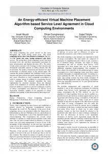
How to elastically scale? Due to the inflexibility in vertical scaling, we opt for horizontal scaling. We also assume one VNF instance-type. A small instance-type is lightweight, can be easily distributed over the network and instantiated ondemand. Moreover, having multiple instance-types unnecessary complicates management tasks. In summary, we consider following elasticity mechanisms: Installing a new VNF instance, Removing an existing VNF instance, Migrating a VNF instance, and Reassigning a demand to another VNF instance. Fig. 1 depicts the above elasticity mechanisms. Initially in Fig. 1a, traffic from 3 requests is served by a single VNF instance v. After sometime the traffic of the first request increases. To accommodate this new workload, a new VNF v ∗ is instantiated and the first request is reassigned to v ∗ (Fig. 1b). Then, traffic of the second request terminates, and allocated resources for this request are released. Because, v is still serving the third request, it is migrated to a more optimal location to reduce bandwidth usage (Fig. 1c). Next, third request terminates, and VNF instance v is removed to save host resources (Fig. 1d). A. Notation 1) Data Center Network: The data center network is denoted as a graph G = (N, A), where N is a set of switches and hosts, while A is a set of links (arcs). We identify host nodes by NH . Capacity of host n ∈ NH is denoted by the maximum number of VNF instances that can be installed on n. Let cn (t) denote the available capacity of n ∈ NH at time t. Let wmn and cmn (t) represent weight and capacity at time t of arc (m, n) ∈ A, respectively. 2) Demand: D(t) is the set of demands at time t. A demand d ∈ D(t) is identified by its two endpoints, source md ∈ N and target nd ∈ N . Let demand nodes refer to sources and targets. A demand needs a unit of traffic b and a unit VNF resource to be served. 3) VNF Instance: V (t) is the set of installed VNF instances at time t. cv (t) denotes the number of demands that VNF instance v can serve at time t. As we use one instance-type, we assume the maximum capacity is C. To show assignments of demands to VNF instances, we use two maps at time t: Dv (t) denoting a set of demands assigned to v and vd (t) representing the VNF instance to which demand d is assigned. B. Simplified Model We refine the above model from two aspects in order to simplify our formulation. First, host and VNF instance constraints are transformed to arc bandwidth capacity constraints; second, demands are simplified: 1) Constraints Transformation: For each host n ∈ NH , cn (0) nodes are added, and we assume that VNF instances are installed on these nodes. These nodes are called VNF nodes. Imagine a VNF instance v is installed on n at time t, and n still has capacity of cn (t) = 2. As shown in Fig. 2a, threeSnodes are added. Fn (t) denotes these nodes, and F (t) = n∈NH (Fn (t)). Each m ∈ Fn (t) is connected to n via arc (m, n). The capacity of arcs initially are set to 2×b×C,
!
VNF instance
"#$ % Source of service traffic ( &#'%
"#$% !
"#$ &
(#)%
"#
%$!*
(#)%
(#)&
"#$ &
!
(#)&
(#)'
"#$ '
"#
%$!)
'(
!"#$
'#(%
%"&$
!
Target of service traffic (
"#$ '
(#)'
"#$ &
!
'#(&
Service traffic increase Service traffic decrease
(b) v ∗ Install. & Reassign.
(a) Initial Placement
(c) Migration of v
(d) Removing v
Figure 1: Elasticity Mechanisms Host (
'
Free VNF Node
!
VNF Node with a VNF Instance
Host (
"
"#
Source of &
$#
Target of &
%#
Qanat of &
"#
# $%&'
"# "#
" !
!
!
"
"
(a) VNF Nodes
$#
!
"# %#
!
$#
$#
(b) Traffic Flow Direction
! $#
(c) Simplifying Demands
Figure 2: Simplified Model as at most, traffic of C number of demands enters and leaves 3) Flow Conservation Constraint: For each node n ∈ N , m. These arcs force that no traffic can enter a VNF instance Eq. 2 guarantees that the amount of traffic entering and leaving node; however, this does not change the problem, because n are equal, where n is not a VNF node or a Qanat. we can assume that the demand traffic is sent to a demand d source from the VNF instance node, instead of the opposite −2byn (t) if n ∈ F (t) X X F direction (Fig. 2b). Let An (t) represent the Sarcs connecting d d xmn (t)− xnm (t) = 2b if n ∈ Q(t) VNF nodes to the node n, and AF (t) = n∈NH (AF n (t)). (m,n)∈A (n,m)∈A 0 otherwise Finally, let nv (t) ∈ F (t) be the VNF instance node hosting S (2) VNF instance v at time t, and NV (t) = v∈V (t) {nv (t)}. 2) Simplifying Demands: By previous transformation, we 4) Pair Connectivity Constraint: Eq. 3 ensures that a Qanat assume that VNF instances send the traffic to demand nodes. We add a node qd called Qanat to the graph for each demand receives traffic from a VNF instance, so both source and target of a demand are connected to the same VNF instance. d ∈ D(t). Traffic is now S received in qd instead of md and nd (Fig. 2c). Let Q(t) = d∈D(t) {qd } denotes all Qanat nodes X ∀d ∈ D(t) : ynd (t) = 1 (3) at time t. A qd is connected to md and nd via arcs (md , qd ) n∈F (t) and (nd , qd ). The capacity of these arcs initially are set to b, and their weights are set to 0. These two arcs ensure that if 5) Installations Cost (Cins (t)): The cost of installed VNF traffic reaches qd , it has met md and nd earlier. instances at time t is defined by Eq. 4. f is the cost of host C. Mathematical Model resources consumed by a VNF instance for each time slot. A discrete-time system is considered to model the problem X Cins (t) = f zn (t) in which time is divided into equal slots 0 ≤ t ≤ T . (4) d n∈F (t) 1) Decision Variables: xmn (t) ∈ R is the amount of traffic for demand d on arc (m, n) ∈ A at time t. We derive 6) Transportation Cost (Ctr (t)): The cost of delivering two variables ynd (t) and zn (t) from xdmn (t). ynd (t) denotes demands traffic at time t is denoted by Eq. 5. g is the cost of if demand d gets traffic from VNF instance node n. zn (t) a unit of bandwidth usage for each time slot. represents if a VNF instance is installed in node n. They are defined as follows. X X ( Ctr (t) = g xdmn (t)wmn d (5) 1 if xnm (t) > 0 d d∈D(t) (m,n)∈A ∀(n, m) ∈ AF (t) : yn (t) = 0 otherwise ( ∀n ∈ F (t) : zn (t) =
P
1
if
0
otherwise
d∈D(t)
ynd (t) > 0
2) Capacity Constraint: Eq. 1 ensures that arcs capacities are not violated. X 0≤ xdmn (t) ≤ cmn (t) for ∀(m, n) ∈ A (1) d∈D(t)
7) Reassignment Cost (Cre (t)): Eq. 6 is the cost of reassigning a set of demands at time t. In this equation, hd (t) is the penalty of reassigning demand d. Here, |ynd (t−1) 6= ynd (t)| is 1 if ynd (t − 1) 6= ynd (t) otherwise is 0. Cre (t) =
X
X
hd (t) (6)
n∈F (t)∩F (t−1) d∈D(t)∩D(t−1)
|ynd (t
− 1) 6=
ynd (t)|
�
8) Migration Cost (Cmig (t)): This is the cost of migrating a set of VNF instances at time t. In Eq. 7, kv (t) is the penalty of migrating VNF instance v. Here, |zn (t − 1) 6= zn (t)| is 1 if zn (t − 1) 6= zn (t), otherwise is 0. X � kv (t)|zn (t − 1) 6= zn (t)| (7) Cmig (t) =
Algorithm 1 Migration Potential 1: function potmig (v, n, R∗ ) 2: C ← Transportation cost of Dv ; 3: C ∗ ← g × f low(n, Dv ∪ {d}, R∗ ) + λ × kv ; 4: return (C − C ∗ ) if (C ∗ is not ∞), otherwise −∞; 5: end function
n∈F (t)∩F (t−1)
9) Objective Function: The objective is to minimize Eq. 8. T � 1X Cins (t) + Ctr (t) + Cre (t) + Cmig (t) T →∞ T t=0
lim
(8)
The static version of EVNFP generalizes to the NP-Hard location routing problem (LRP) [3]. An optimal solution needs solving a dynamic version of LRP for each time slot. Due to its intractability, it is not possible to solve the problem for large datacenters. Thus, we break down the problem and solve it independently for each demand arrival or departure. Let Tˆ be a time system, and at each t ∈ Tˆ, an arrival or departure occurs. We rewrite the objective function as Eq. 9. Here, λt is a weight factor to balance the transportation and installation costs with the migration and reassignment costs. �X � X min (Cins (t) + Ctr (t)) + λt (Cre (t) + Cmig (t)) (9) t∈Tˆ
t∈Tˆ
Although, this problem is easier than the original one, the static version still generalizes to LRP. Hence, we propose a heuristic algorithm for solving this problem in the next section. IV. S IMPLE L AZY FACILITY L OCATION In this section, we describe our solution, Simple Lazy Facility Location (SLFL), including two novel heuristics to handle arrival and departure events. For simplicity, we omit time variable t. Also, we assume function f low(n, D∗ , R∗ ) that finds the optimal routing of traffic between node n and demands D∗ , and stores the routes in R∗ . This function finds R∗ in polynomial time by solving the single-commodity mincost flow problem [14]. A. Demand Arrival Upon new demand d arrival, a combination of installation, migrations and reassignments can be applied to optimize the placement. Since in most cases the arrival affects its locality, SLFL locally optimizes the placement. Three possible actions are considered: (i) assignment to an existing VNF instance, (ii) migration and (iii) installing a new VNF instance followed by a set of reassignments. The first action assigns d to an existing VNF instance with the minimum transportation cost. For the two other actions, migration potential and installation potential metrics are defined as follows: Migration potential is the difference between current transportation cost of Dv and transportation cost of Dv ∪ {d} after possible migration of v to node n. Function potmig , defined in algorithm 1, finds this potential and stores routes in R∗ . Installation potential is the difference between the operational cost before and after installing a VNF instance in node
n. We consider a set of reassignments during installation. Function potins , as defined in Algorithm 2, computes the installation potential for a node n, finds candidate demands D∗ for reassignment, and stores routes in R∗ . Algorithm 2 Installation Potential 1: function potins (n, R∗ ) 2: e∗ ← −g × f low(n, {d}, R∗ ); D∗ ← ∅; 3: for j = 1 to C − 1 do 4: d∗ ← Find best next demand to reassign; 5: e ← C − (g × f low(n, D∗ ∪ {d, d∗ }, R) + λ × hd∗ ); 6: break if (e ≤ 0 or e ≤ e∗ ); 7: e∗ ← e; D∗ ← D∗ ∪ {d∗ }; R∗ ← R; 8: end for 9: return (e∗ − f , D∗ ); 10: end function
Alg. 3 shows how SLFL handles a demand arrival. The cost of the best assignment is found (lines 3-4). The best migration and installation potential are computed (lines 4-8). If the best installation potential is greater than the best migration potential, a new VNF v is instantiated and demands Dre are reassigned to v (lines 9-14). Otherwise, VNF instance vmig is migrated to nmig (lines 14-17). Finally, in the lack of potential to change, d is assigned to VNF instance vasn . Algorithm 3 SLFL-Demand Arrival 1: function D EMANDA RRIVAL(d) 2: D ← D ∪ {d}; 3: vasn ← arg minv∈V {f low(nv , {d}, ∅)} ∗ ); 4: pasn ← g × f low(nvasg , {d}, Rasg 5: (vmig , nmig ) ← arg maxv∈V :n∈F {potmig (v, n, ∅)}; ∗ 6: emig ← potmig (vmig , Rmig ); 7: nins ← arg maxn∈F/NV {potins (n, ∅)}; ∗ ); 8: (eins , Dre ) ← potins (nins , Rins 9: if (eins > −pasn ) and (eins ≥ emig ) then 10: u ← install a facility at nins ; 11: Reassign ∀d ∈ Dre and assign d to u; ∗ 12: Route related traffic based on Rins ; 13: V ← V ∪ {u}; 14: else if emig > −pasn then 15: Migrate vmig to node nmig ; 16: Assign d to vmig ; ∗ 17: Route traffic based on Rmig ; 18: else 19: Assign d to vasn ; ∗ 20: Route traffic based on Rasg ; 21: end if 22: end function
B. Demand Departure Similar to an arrival event, SLFL locally optimizes the placement of VNF instances upon departure of demand d. Assume that d was assigned to VNF instance v. Two actions
are considered: (i) migration of v, and (ii) removal of v. We define emigration potential and removal potential metrics for migration and removal of v as follows: Emigration potential defined in Alg. 4 is the difference in transportation cost of Dv before and after migration of v to node n. Algorithm 4 Emigration Potential 1: function potemg (v, n, R∗ ) 2: C ← Transportation cost of Dv ; 3: C ∗ ← g × f low(n, Dv , R∗ ) + λ × kv ; 4: return (C − C ∗ ) if C ∗ is not ∞, otherwise −∞; 5: end function
Removal potential is the difference in operational-cost before and after the removal of v. Similar to installation potential, a set of reassignments are considered. Function potrmv , defined in Alg. 5, computes the removal potential of v, finds candidate VNF instances Vre for reassignment of Dv , and stores routes in R∗ . Algorithm 5 Removing Potential 1: function potrmv (v, R∗ ) 2: {Dre , Vre } ← {∅, ∅}; e∗ ← f ; 3: C ← Transportation cost of Dv ; 4: C ∗ ← 0; U ← V /{v}; 5: for all dv ∈ Dv do 6: vre ← best VNF instance for reassignment of dv ; ∗ ) + λ × hd v ; 7: C ∗ ← C ∗ + g × f low(nvre , {i}, Rre ∗ 8: if C is ∞ then 9: e∗ ← 0; {Dre , Vre } ← {∅, ∅}; 10: break; 11: end if 12: {Vre , Dre } ← {Vre ∪ vre , Dre ∪ d}; ∗ 13: R∗ ← R∗ ∪ Rre ; 14: end for � 15: return e∗ + (C − C ∗ ), {Dre , Vre } ; 16: end function
Finally, algorithm 6 defines how SLFL handles a demand departure. First, v’s resources assigned to d are released (line 2). Then, the best node to migrate and emigration potential are computed (lines 3-4). The removal potential and possible reassignments are determined (line 5). If removal potential is positive and greater than emigration potential, v is removed and its demands are reassigned to other VNF instances (lines 6-12). Otherwise, if emigration potential is positive, v is migrated to a more optimal node (lines 13-16). V. E VALUATION A. Experimental Setup We have implemented SLFL1 and evaluated its performance by simulations on a data center topology with 99 nodes (45 switches and 54 hosts). We used a 6-ary Fat-tree topology [2] providing full bisection bandwidth. Each host has 8 CPU cores, 8GB of memory, and contains a 1Gbps network adapter. A host CPU consumes 140W of power at electricity cost of
Algorithm 6 SLFL-Demand Departure 1: function D EMAND D EPARTURE(d, v) 2: Release v’s resources assigned to d; 3: nemg ← arg maxn∈F/NV {potemg (v, n, ∅)}; ∗ 4: eemg ← potemg (v, nemg , Remg ); ∗ 5: (ermv , {Dre , Vre }) ← potrmv (v, Rrmv ); 6: if (ermv > 0) and (ermv > eemg ) then 7: V ← V /{v}; 8: Remove facility v; 9: for all {dre , vre } ∈ {Dre , Vre } do 10: Reassign dre to vre ; 11: end for ∗ 12: Route traffic based to Rrmv ; 13: else if eemg > 0 then 14: Migrate v to the node nemg ; ∗ 15: Route traffic based to Remg ; 16: end if 17: end function
¢11 per kWh2 . We select Bro IDS 3 as a representative VNF providing a capacity of 80 Mbps. We assume that Bro can be installed on a VM which requires 1 vCPU and, 1GB of memory. In regards to bandwidth, we set the cost of using a unit of bandwidth for a link to 20% of the power consumption cost. Regrading the migration penalty kv (t), the full memory (1GB) of VNF instance v is transported from original VNF node nv (t − 1) to new VNF node nv (t). The reassignment penalty hd (t) involves transporting a fraction of memory of VNF instance vd (t − 1) to new VNF instance vd (t). This fraction is relative to the VNF instance’s maximum capacity. We model demand arrival using Poisson distribution with an average rate of 1 demand per second. The lifetime of a demand follows an exponential distribution with an average of 1800 seconds. Demand nodes are uniformly distributed in the data-center network. We set b = 20Mbps and λ = 1. We compare SLFL with Random and First-Fit placements. Upon a demand arrival, Random placement randomly selects a VNF instance with the sufficient residual capacity and bandwidth. Otherwise, a VNF instance is installed in a random not-saturated host with enough bandwidth. First-Fit selects the first not-saturated VNF instance with adequate residual bandwidth. If not, a VNF instance is installed in the first not-saturated host with adequate available bandwidth. Upon demand departure, both algorithms remove a VNF instance if this instance has no assigned demand. B. Acceptance and Utilization Fig. 3 depicts workload acceptance and resources utilization. As shown in Fig. 3a, SLFL accepts 97% of workload whereas Random and First-Fit accept 48% and 45% of workload, respectively. Bandwidth, host, and VNF resource utilization are depicted in Fig. 3b, Fig. 3c and Fig. 3d, respectively. Random and First-Fit quickly exhaust bandwidth resources (utilization of 94% and 92%, respectively) causing low host resource utilization (45% and 44%, respectively). 2 Electric
1 https://github.com/miladghaznavi/Elastic-VNF-Placement
3 The
Power Monthly, www.eia.gov/electricity/monthly/pdf/epm.pdf. Bro Network Security Monitor, www.bro.org
100
100 Random SLFL FirstFit
80 60
100 Random SLFL FirstFit
80 60
100 Random SLFL FirstFit
80 60
60
40
40
40
40
20
20
20
20
0
0
0
0
0
0 0 0 0 0 0 0 00 00 00 00 00 00 00 00 50 10 15 20 25 30 35 40
0 0 0 0 0 0 0 00 00 00 00 00 00 00 00 50 10 15 20 25 30 35 40
Time (s)
Time (s)
(a) Workload Acceptance
Random SLFL FirstFit
80
0 0
0 0 0 0 0 0 0 00 00 00 00 00 00 00 00 50 10 15 20 25 30 35 40
0
0 0 0 0 0 0 0 00 00 00 00 00 00 00 00 50 10 15 20 25 30 35 40
Time (s)
(b) Bandwidth Res. Utilization
Time (s)
(c) Host Res. Utilization
(d) VNF Res. Utilization
140 120 100 80 60 40 20 0
Random SLFL FirstFit
0
Cost (¢per 200 sec.)
Cost (¢per 200 sec.)
Figure 3: Workload Acceptance and Resource Utilization 140 120 100 80 60 40 20 0
Random SLFL FirstFit
0
0 0 0 0 0 0 0 00 00 500 000 500 000 500 000 50 10 1 2 2 3 3 4
0 0 0 0 0 0 0 00 00 500 000 500 000 500 000 50 10 1 2 2 3 3 4
Time (s)
Time (s)
140 120 100 80 60 40 20 0
Random SLFL FirstFit
(b) Transportation Cost 101 Reassignment Migration
100 ¢per 200 sec.
Cost (¢per 200 sec.)
(a) Total Operational Cost
10−1 10−2 10−3 10−4
0
0 0 0 0 0 0 0 00 00 500 000 500 000 500 000 50 10 1 2 2 3 3 4
Time (s)
10−5 0
0 0 0 0 0 0 0 00 00 500 000 500 000 500 000 50 10 1 2 2 3 3 4
(c) Installation Cost
(d) Overhead
Figure 4: Operational Costs Moreover, these placements utilize 88% and 87% of VNF resources, respectively. SLFL achieves bandwidth, host and VNF resource utilization of 82%, 91% and 98%, respectively. C. Operational Cost Operational costs are reported in Fig. 4. Compared to Random and First-Fit, SLFL incurs 9% and 4% less operational cost (Fig. 4a), and pays 22% and 19% less bandwidth cost (Fig. 4b), respectively. However, SLFL incurs two times more installation cost (Fig. 4c) compared to the Random and FirstFit. The reason is that SLFL accepts two times more workload than the other approaches. Finally, Fig. 4d shows the overhead of SLFL. SLFL does reassignments more frequently than migrations. The reason is that a reassignment requires moving of a part of VNF instance state, whereas a migration requires moving of the entire memory of the VNF instance. VI. C ONCLUSION We introduced Elastic Virtual Network Function Placement (EVNFP) problem presenting a model to minimize operational costs in providing VNF as a service. This model considered the elasticity overhead and the trade-off between bandwidth and host resource consumption. We developed and evaluated an algorithm, named SLFL, to solve this problem in polynomial time. Our experiments suggest that by taking both bandwidth and host resources into consideration, and by carefully selecting the right elasticity mechanism, SLFL accepts ∼ 2× more workload in comparison to first-fit and random placements. Additionally, SLFL incurs 5–8% less operational cost.
VII. ACKNOWLEDGEMENT This work was supported by the Natural Science and Engineering Council of Canada (NSERC) under the Smart Applications on Virtual Infrastructure (SAVI) Research Network. R EFERENCES [1] Microsoft azure. http://www.microsoft.com/azure/default.mspx. [2] M. Al-Fares, A. Loukissas, and A. Vahdat. A Scalable, Commodity Data Center Network Architecture. In ACM SIGCOMM 2008. [3] M. Albareda-Sambola, J. A. Dıaz, and E. Fern´andez. A compact model and tight bounds for a combined location-routing problem. Computers & Operations Research, 32(3):407–428, 2005. [4] A. Beloglazov et al. A taxonomy and survey of energy-efficient data centers and cloud computing systems. Academic Press, 2011. [5] O. Biran et al. A stable network-aware vm placement for cloud systems. In CCGRID, pages 498–506, 2012. [6] M. Bouet, J. Leguay, and V. Conan. Cost-based placement of vdpi functions in nfv infrastructures. In NetSoft, 2015. [7] C. Clark, K. Fraser, S. Hand, J. G. Hansen, E. Jul, C. Limpach, I. Pratt, and A. Warfield. Live migration of virtual machines. In NSDI, 2005. [8] S. Clayman, E. Maini, A. Galis, A. Manzalini, and N. Mazzocca. The dynamic placement of virtual network functions. In IEEE NOMS, 2014. [9] Amazon EC2. http://aws.amazon.com/ec2/. [10] W Ahmad et. al. A survey on virtual machine migration and server consolidation frameworks for cloud data centers. Journal of Network and Computer Applications, 52(0):11 – 25, 2015. [11] Guilherme Galante et al. A survey on cloud computing elasticity. UCC 2012, pages 263–270. IEEE Computer Society, 2012. [12] A. Gember, R. Grandl, A. Anand, T. Benson, and A. Akella. Stratos: Virtual middleboxes as first-class entities. UW-Madison TR1771, 2012. [13] A. Gember-Jacobson et al. Opennf: Enabling innovation in network function control. In ACM SIGCOMM, 2014. [14] A. V. Goldberg and R. E. Tarjan. Finding minimum-cost circulations by canceling negative cycles. JACM, 36(4):873–886, 1989. [15] Z. Gong, X. Gu, and J. Wilkes. Press: Predictive elastic resource scaling for cloud systems. In IEEE CNSM, 2010. [16] F. Hermenier, X. Lorca, J. M. Menaud, G. Muller, and J. Lawall. Entropy: A consolidation manager for clusters. In ACM SIGPLAN/SIGOPS. [17] M. A. Lopez and O. Duarte. Providing elasticity to intrusion detection systems in virtualized software defined networks. [18] V. Mann, A. Kumar, P. Dutta, and S. Kalyanaraman. Vmflow: Leveraging vm mobility to reduce network power costs in data centers. In IFIP NETWORKING, 2011. [19] X. Meng, V. Pappas, and L. Zhang. Improving the scalability of data center networks with traffic-aware virtual machine placement. In IEEE INFOCOM, 2010. [20] M. Sedaghat, F. Hernandez-Rodriguez, and E. Elmroth. A virtual machine re-packing approach to the horizontal vs. vertical elasticity trade-off for cloud autoscaling. In ACM CAC, 2013. [21] U. Sharma, P. Shenoy, S. Sahu, and A. Shaikh. A cost-aware elasticity provisioning system for the cloud. In IEEE ICDCS 2011. [22] Z. Shen, S. Subbiah, X. Gu, and J. Wilkes. Cloudscale: Elastic resource scaling for multi-tenant cloud systems. In ACM SoCC, 2011. [23] A. Verma, P. Ahuja, and A. Neogi. pmapper: Power and migration cost aware application placement in virtualized systems. In ACM/IFIP/USENIX Middleware, 2008.