1
Dynamically Encapsulated Trees for Stealth Multicast with MYDEKI A. Striegel Systems & Software Laboratory Dept. of Computer Science & Engineering University of Notre Dame Notre Dame, IN 46530 USA E-mail:
[email protected]
Abstract— While network-level multicast has tremendous potential for increasing the efficiency of grouporiented applications, the adoption of network-level multicast has been tepid at best. In the absence of full multicast support in the network, group-oriented application developers are forced to turn to either Application-Level Multicast (ALM) or separate unicasts. Although ALM does introduce the basic efficiency of multicast, ALM requires active modifications to the application and does not provide a clear incentive for pursuing global networklevel multicast support. In this paper, we propose a novel concept entitled stealth multicast that allows for practical adoption of network-level multicast on a domain-wise basis rather than global scale. In the stealth multicast model, similar unicast packets are dynamically assembled into virtual groups for multicast transmission across the domain. At the edge of the domain, the packets are converted back to unicast, thus hiding the existence of stealth multicast from the external Internet. True to its namesake, stealth multicast operates in complete stealth, providing seamless interoperability without requiring any modifications to end-user applications nor requiring any inter-domain support. In this paper, we introduce the basic concepts of stealth multicast and show that the stealth multicast model can offer significant benefits in terms of bandwidth savings with minimal impact to the end-user QoS.
distribution trees and a dependence upon a rich enduser capacity to provide adequate downstream branching. Despite its weaknesses, ALM offers a compelling solution for bandwidth management as it avoids one of the key problems associated with network-level multicast, namely global network deployment. Whereas much can be written about the tepid adoption of network-level multicast, the root of the problem arises from the fact that much of the benefit of network-level multicast only comes with complete global deployment. The challenge of global network-level multicast support appears especially daunting given that many other complex sub-issues also provide obstacles such as the support vs. development vs. demand dilemma, deployment complexity (billing, management), and ISP economic incentive [7]. Thus, our paper poses the following question, is it possible to offer a novel approach to multicast that allows for incremental deployment while avoiding the pitfalls that have plagued network-level multicast deployment (application adoption, ISP incentive, etc.)? This question provides the basis for the model proposed in our paper, stealth multicasting.
Keywords: Multicast Deployment, Routing, QoS
At its core, the stealth multicast model changes the context of the problem regarding multicast deployment. Rather than requiring participation on a global scale (via tunneling, inter-domain routing, or application support), stealth multicast abstracts multicast transport in an individual domain (Autonomous System) such that its entire presence operation is kept hidden from the outside world. At the edge of the domain, packets are dynamically converted to and from multicast, thus allowing for seamless interaction with existing unicast applications. The conversion for multicast is done only at inputs to the domain whereby maximum rewards can be gleaned through reduction to multicast transport.
I. I NTRODUCTION While fundamental multicast concepts have been successfully deployed in the Mbone and exist in many commercially available routers, recent studies show a relatively lackluster adoption over the last decade [1], [2]. Furthermore, despite the large body of research on network-level multicast [3]–[5], recent trends in multicast research have shifted to application-level multicast (ALM) [6]. Although techniques such as ALM can offer near network-level multicast bandwidth savings, ALM can suffer from additional delay due to longer
A. Stealth Multicast Overview
2
Company LAN
Unicast Company LAN + Uplink
Fig. 1.
Other Domains
Stealth Multicast Module
Multicast
Unicast
ISP Domain
Other domains
The stealth multicast model
Hence, the target audience for stealth multicast is domains directly serving UDP applications that send out identical data streams to multiple users (i.e. streaming videoconference, on-line games, p2p applications) that network characteristics that ALM cannot meet (minimal delay, reduced client capabilities, etc.). While stealth multicast defines a novel framework for multicast operation, the model itself leaves several options open for customization. Hence, we introduce an architecture called MYDEKI that is based on the fundamental principles of the stealth multicast model. We examine the parameters for the MYDEKI model and the intuition behind the parameters in depth with regards to performance. Furthermore, we consider various aspects of the stealth multicast model in regards to areas such as IPv6, IPSec, and TCP. We believe that stealth multicasting offers a truly unique approach that will catalyze the deployment of multicast and in turn, improve the underlying network efficiency throughout the Internet. The rest of our paper is organized as follows. In Section II, we present the fundamentals of the stealth multicast model. Next, in Section III, we present the MYDEKI model. Then, in Section IV we conduct simulation studies regarding the performance of the MYDEKI model. In Section V, we discuss various other considerations for stealth multicast and comment on several areas for future research. Finally, in Section VI we offer several concluding remarks and discuss our future work. II. T HE S TEALTH M ULTICASTING M ODEL In order to provide seamless interoperability with minimal end-system modification, the stealth multicast model relies on two governing principles that are as follows: • Externally transparent: External unicast applications should not require any modifications in order to operate in the stealth multicast environment. The
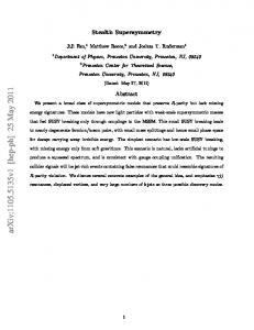
same applies for existing multicast applications (if present). • Negligible QoS impact: The end-user should not experience a noticeable impact in QoS. With the first principle of external transparency, the goal is to provide seamless functionality with existing networks. This principle is extremely critical due to the tremendous number of applications currently in use, many of which may be extremely difficult or even impossible to change. Note that this principle does not preclude future applications from taking advantage of the stealth multicast model, ALM, or or network-level multicast but rather ensures backwards compatibility with existing IP unicast applications. The second principle ties into the first principle and into the stealth of the model itself. If the QoS of the user is significantly impacted in either the positive or the negative direction, the fact that stealth multicast is being employed may be discernible. A significant QoS change may impact the functionality of the applications utilizing the network as well. Although a positive QoS impact may not necessarily generate criticism, a negative impact on QoS will certainly cause issues with application functionality. However, this principle has an inherent amount of flexibility due to the fact that only a ‘noticeable’ QoS impact causes any issues. Due to the fact that QoS is subject to both the perception of the end user and the requirements of the application, it is the prerogative of the network administrator to determine what constitutes a noticeable QoS impact. For our paper, we define the term noticeable QoS impact to refer to the end user attributing the poor network performance to something other than the typical variations in Internet traffic behavior. A. Stealth Multicast Operation Figure 1 shows the overall concept of the stealth multicast model. The key component of the stealth multicast model is the Virtual Group Detection Module (VGDM) that is shown in Figure 2. The VGDM is placed at the edge of the domain and queues packets for assembly into virtual groups for multicast transport across the domain. The stealth multicast process begins as a grouporiented application transmits packets via separate unicasts to multiple clients. The packets travel via the uplink to the domain and arrive at the edge router (see Figure 1). The packets are then transferred to the VGDM for virtual group consideration. A filter may be applied at the edge router to remove packets from consideration that should not or would never become part of a virtual group. Examples of such packets would include existing multicast packets, ICMP, and RSVP.
3 Stealth Multicast Module
Virtual Group Manager
Checksum Calculation Heuristic
Filter
Dispatch
Tree Construction
Encapsulation State Info
Rules
Edge From Company Unicast
Fig. 2.
Router
To ISP Domain Unicast/Multicast
Stealth multicast module - basic components
Depending upon the behavior desired and involvement of the source application, the VGDM may be placed along the path at various points in the network. While placement at the edge of an ISP’s domain such as in Figure 1 would allow for maximum stealth and benefit solely for the ISP, the VGDM could alternatively be placed at the edge of the customer LAN to decrease the load on the uplink to the domain. Furthermore, the VGDM could also be placed on an incoming link from another domain. However, as will be discussed later, the stealth and utility of such placement may be reduced depending upon the nature of the underlying traffic. For conceptual purposes, the VGDM can be viewed as a collection of COTS hardware dedicated to serving an uplink whose traffic can benefit significantly from stealth multicast. Figure 2 shows the steps involved once the packet arrives at the VGDM which are discussed below. Initial Filter: Once a packet arrives at the VGDM, the first step is to apply a basic filter to the packet. The packet is filtered according to a set of rules as defined by the network administrator. For instance, an admin could define that customer A’s traffic should never be considered for stealth multicast or that FTP traffic should never be considered as a candidate for stealth multicast. The rules may also be generated by heuristics monitoring the incoming flows to optimize the candidates for consideration. An example of a heuristic might be noting that traffic on port 412 has not been converted to any virtual groups (insufficient matches) and should not be considered for the next 2 hours. Checksum Calculation: If a packet passes the filter, it is uniquely categorized according to its data contents. The checksum calculation module creates a checksum
that uniquely identifies the payload of the data packet. The checksum must be sufficient such that two unique payloads of the same size do not compute to the same checksum. If the checksum calculation is imprecise, the transparency principle of the model will be broken as different packets would be combined into a single virtual group, thus giving one client the wrong data payload. The checksum module is only interested in the data payload as the remaining header information (IP, UDP) is handled by the virtual group manager. The checksum (digital signature) is computed using COTS hardware [8], [9]. Virtual Group Manager: Next, the packet is passed to the virtual group manager for placement into virtual groups (queues). The virtual groups are uniquely identified by the checksum, the packet size, the source IP, and the source port. In addition, other potential information for each packet such as the DS field (for DiffServ networks) may also be preserved on a packet-wise basis. The packets themselves are queued in the virtual group until an appropriate trigger causes the virtual group to be dispatched. The triggers for dispatch are the defining components for the performance of the virtual group manager. Examples of triggers/criterion may include parameters such as timers (maximum time in the queue), minimum requirements (minimum numbers to constitute a group), as well as maximum requirements (maximum group size). The criterion determine both the performance (additional multicast efficiency) as well as the impact on end-user QoS introduced by the VGDM (see Figure 3). For instance, if packets are held too long, the end-toend delay increase may be noticeable by the end user. In contrast, if packets are not held sufficiently long enough, the aggregation of the underlying traffic may prevent the sufficient detection of matches to make the VGDM useful. While the effect of aggregation can be mitigated by pushing the VGDM closer to the source or using the VGDM only on links that would benefit, the tradeoff in queuing delay is directly dependent upon the QoS requirements of the application and the total end-to-end delay of the path to the destination. Tree Construction: After a sufficient stimulus has occurred (time, size, etc.), the packets are given to the dispatch mechanism for transmission onwards. Providing that the virtual group has sufficient membership to justify the use of multicast transport, the packet is given to the tree construction module. If the size of the virtual group is not sufficient, the packets are simply released as standard unicast packets back to the edge router. The tree construction module is responsible for de-
4
Group Detection Efficiency
QoS Delay
Benefit/ Maximum Acceptable Delay Impact
Delay
Minimum Acceptable Multicast Gain
Virtual Group Delay
Fig. 3.
Tradeoff - efficiency versus QoS impact
termining how to transport the multicast packet across the domain. This may include broadcast, pre-constructed virtual trees, ALM, or other methods [10]. At the tree construction module, the packet is appropriately modified to employ the multicast transport mechanism and given to the state information module. Encapsulation of State Information: One of the inherent problems in stealth multicast is that virtual groups are constructed dynamically, i.e. the makeup of the end clients is not know a priori. In addition, since it is assumed that multicast does not exist outside of the ISP domain, the packets must be converted back to unicast at the edge of the domain. However, using standard IP multicast which contains only the source IP/ destination group address, the edge routers would not know whom is responsible for sending the unicast packet nor the unique portions of the headers (DS field, destination IP, UDP destination port). Hence, additional state information must be included in the packet or kept at the egress routers to identify how the packet should be converted back to unicast. Transmission & Exit: After the packet has been modified for multicast transport (tree construction) and the state information has been added (encapsulation), the packet is given back to the edge router. The edge router then forwards the packet across the domain using the underlying multicast transport mechanism (broadcast, route-pinning, ALM, etc.). Once the packet reaches the edge of the domain, the egress router is responsible for converting the packet back into a unicast packet. Using the virtual group state information, the egress router reconstructs the appropriate unicast packets and forwards the replicated unicast packets onwards. The packets are identical to the packets that were originally seen at the VGDM with appropriate modifications for TTL and any other necessary fields. Once the packet leaves the domain, it is a standard unicast packet, indistinguishable
from any other unicast packets that did not undergo multicast consolidation/transport across the domain. To both the application sending the packets and the client receiving the packets, there is no difference in the contents of the packets nor a noticeable change in the QoS of the packet. However, there is certainly a noticeable impact for the domain. In addition to avoiding upstream bottlenecks, the general bandwidth requirements of the domain are alleviated due to the use of multicast. In fact, stealth multicast allows for a clear transition of deployment from the bare minimum (entirely stealthful - domain only) to full network-level multicast (see Table I). Most notably, stealth multicast allows a domain to deploy multicast support and realize concrete benefits without waiting for application, customer, or global routing support. III. T HE MYDEKI A RCHITECTURE The MYDEKI (Multicast and You Don’t Even Know It) is an architecture based on the stealth multicast model. The MYDEKI architecture governs the undefined areas of stealth multicast which include virtual group management, multicast transport, and state management. In this section, we define how MYDEKI addresses these areas, the parameters of MYDEKI, and the intuition behind the various architectural choices for MYDEKI. The MYDEKI architecture is targeted towards medium-size (tens to hundreds of clients) UDP1 grouporiented applications employing separate unicasts. These applications may either operate with or without knowledge of MYDEKI. The MYDEKI architecture offers three modes of deployment, two stealth modes (differing by the location of the VGDM), and an applicationassisted mode. The three architectures are summarized briefly below: • MYDEKI-FullStealth: In this setting, the VGDM is located at the edge of the domain. The incoming link is a single customer whose traffic has been identified as being highly suitable for stealth multicast. This mode operates in stealth completely and is imperceptible to the applications, customer, or end users. • MYDEKI-Local: The VGDM is pushed towards the customer where it resides at the edge router of the customer. Packets may be multicast on the uplink, thus offering significant savings in terms of upstream bandwidth. This mode also operates in stealth in regards to the applications but the customer is aware of the presence of the VGDM. 1 Although MYDEKI can be adapted for limited TCP support, such a topic is beyond the scope of this paper.
5
Approach Application Internet ISP VGDM Detection Accuracy Benefits Costs
Pure Multicast Multicast Multicast Multicast None
Application Assisted Stealth Unicast Stealth ISP
Customer Aware Unicast Unicast Stealth At company
Stealth Mode Unicast Unicast Stealth At ISP edge
Unicast Unicast Unicast Unicast None
Perfect Customer, ISP App changes Deployment
Perfect Customer, ISP App changes Deployment
Good Customer, ISP
OK ISP
None None
Deployment
Deployment
TABLE I M ULTICAST TRANSITION OPTIONS
•
MHT Max hold time
MYDEKI-App: In this version, the VGDM resides at the edge router of the ISP. The application actively participates by sending packets complete with virtual group state information to the VGDM which then converts the packets for multicast transport. This mode operates in stealth in terms of the end client but requires active participation from the customer and modification of the server applications.
1 0 0 1 0 1 0 1
Search time
TSW
Search pkts
PSW
1 0 0 1 0 1 0 1
Missed packets
1 0 0 1 0 1 0 1
1 0 0 1 0 1 0 1
time
1st packet for group
A. MYDEKI: Stealth Mode (FullStealth and Local) In the stealth mode of MYDEKI, all applications are unaware of the presence that stealth multicast is being employed. The first contact that the architecture has with the packet occurs when the candidate packet is presented to the VGDM (see Figure 2). Dispatch Mechanism: As noted earlier, the triggers and operation of the dispatch mechanism truly define the performance of any architecture based on stealth multicast. The intuition behind the MYDEKI parameters is to allow for predictable tuning by the network administrator. At their core, the MYDEKI parameters capture the potential benefits of waiting (receiving another packet that can be put into a virtual group) versus the effect that the queuing (delay, buffer size) is having on the behavior of the packet flow. For optimal performance, a packet should be kept as a group candidate so as long as only to add more egress points to the multicast group and hence increase the efficiency of the virtual group. Thus, MYDEKI includes triggers that reward close proximity of matching packets (likely to have another match) while still putting a firm cap on the maximum delay that can be experienced by a packet. The following parameters govern how MYDEKI manages the triggers for release for its virtual groups (see Figure 4): • PSW - Packet Scan Width: The number of packets to scan before the virtual group is released. In the
Fig. 4.
•
•
MYDEKI - search settings
event of a new addition to the virtual group, this count is reset. TSW - Time Scan Width: The amount of time to scan before the virtual group is released. Similar to the PSW, this timer is reset upon the addition of a new packet to the virtual group. MHT - Maximum Hold Time: The maximum time that a virtual group can exist and hence the maximum time that a packet can sit inside a queue. This timer is set when the virtual group is started and places a maximum delay on the queuing time, regardless of additions to the virtual group.
Once a packet is triggered for release, it is given to the dispatch mechanism for dispatch to either the multicast modules or dispatch via standard unicast routing (no virtual group constructed). Figure 5 shows the effects of the MYDEKI group settings that are discussed in more detail below: •
•
MaxGS - Maximum Group Size: This parameter forces a group to be dispatched when it passes a specific size. The intuition is that the group has passed a minimum efficiency floor and should be dispatched as soon as possible. MinGS - Minimum Group Size: In order to be
6
New Group
Multicast
Unicast Virtual Group Source IP Source Port Size, Checksum
Fig. 5.
Max Group Size
Min Group Size
MaxGS
MinGS
MYDEKI- virtual group settings
considered as a candidate for multicast, a group must meet a certain minimum membership level. Due to the additional overhead of state information and transport information (if necessary), it may be more efficient to employ separate unicasts if the virtual group membership is very small. Note that both P SW and T SW (proximity rewards) may be employed or only T SW may be used. The P SW setting governs the search width from the perspective of flow aggregation / virtual group detection (i.e. how mixed is the packet in the incoming aggregate flow) whereas T SW reduces queuing time in the event of idle time on the link. Intuitively, the closer that the VGDM is to the source, the tighter the P SW/T SW values that can be employed. If the VGDM is located extremely close to the traffic source, there is a much better chance that virtual group packets will be located close together. As the VGDM is placed farther away from the source, there is a decreasing chance for group detection due to the fact that the group traffic may be interspersed with traffic from other sources or applications. For example, the traffic on a link from another domain would be a much poorer candidate than the traffic from a server hosting company. The search width may also be affected by the OS sending the packets as well as the scheduling mechanisms leading up to the VGDM. The M HT setting allows one to controllably affect the delay impact of virtual group detection. The M HT places a worst case delay on the virtual group detection while the actual delay experienced will depend upon the underlying traffic patterns and the T SW /P SW settings. Although ideally all of the packets would become virtual group members and be multicast across the domain, this will most definitely not be the case in practice. Hence, the P SW and T SW parameters limit the effective search for a given packet and limit the queuing delay of non-multicast packets even further. While one could operate using only M HT , the P SW and T SW allow
the virtual group manager to quickly empty out nongrowing virtual groups (and hence non-contributing). The notion of the total number of groups introduces a significant factor for setting of the dispatch triggers in MYDEKI, the maximum number of concurrent virtual groups (i.e. buffer size). Since the number of virtual groups and the storage required for such groups and their packets cannot be considered infinite, the parameters should be set to minimize overflow conditions. Unlike traditional queue overflows where the packets are discarded, overflow packets are still forwarded onwards via unicast. Thus, overflow does not introduce catastrophic failure. However, once the capacity of virtual groups has been filled, no additional efficiency gains due to stealth multicast will occur until several of the existing virtual groups are dispatched. Furthermore, the filter (static and heuristic rules) at the entrance of the VGDM and the P SW /T SW parameters can have a profound impact in ensuring that the maximum number of virtual groups is not exceeded. Tree Construction & Multicast Transport: In order for a virtual group to be sent using multicast, it must first pass a minimum threshold (M inGS ). Unlike standard IP multicast, the stealth multicast model introduces an overhead (transport information, state information) that must be offset by sufficient tree savings in order to offer an improvement in efficiency. The aspect of tree construction is encompasses how multicast packets are transported across the domain of the ISP. Since the destinations that make up the virtual group are not known a priori, we propose to use an encapsulation-based method for providing multicast transport across the domain [10], [11]. In short, an encapsulation-based approach includes the multicast tree inside the packet, thereby removing the need for multicast state along the routers in the multicast path. For MYDEKI, we have selected the DSMCast approach [10] as it was targeted towards multicast transport across a single domain. In addition, DSMCast offers several key attributes that make it especially useful for stealth multicast which include: •
•
Dynamically pinned header: The path across the domain is explicitly stated in the DSMCast header, thus allowing the VGDM to set the tree path dynamically. The use of an encapsulated header also frees the core from maintaining any multicast state information. Resource management: The exact cost of the multicast transport is know at the ingress, thus vastly simplifying issues such as ingress shaping, resource management, and billing [12].
7 Tree ISP Domain
IP
Multicast Destination Address
Fig. 6.
DSMCast
Server Bank
State
UDP
Edge
Dest IP
5 5 10 15 3
129.186.5.4 129.168.6.20 143.24.6.4 102.67.8.25 50.6.8.20
VGDM Location A = MYDEKI-Local B = MYDEKI-FullStealth
Payload
Dest Port 7894 2004 5003 5796 6901
Company LAN
Fig. 7.
State Management: While the encapsulation-based transport allows for a stateless core to cross the domain, the unique portions of the packet (destination IP, destination port) must also be addressed. Furthermore, each unicast conversion must be appropriately associated with an egress point for the domain. Otherwise, it is extremely difficult for an egress point to accurately assess if it is responsible for converting a multicast packet for a specific destination. Similar to how the encapsulation-based transport includes the tree information in the packet, the state information in MYDEKI is also bundled in the packet. While a more complicated scheme for egress storage of state information would save additional bandwidth, the inclusion of the state information in the packet makes the process as simple as possible. In MYDEKI, each multicast packet includes three pieces of information for each client that is covered by the multicast packet (see Figure 6), the egress point (who should convert the packet), the destination IP, and the destination port. Upon receiving a multicast packet, an edge (egress) router will inspect the packet to determine if it should appropriately convert/replicate the packet. In the figure, router 5 would dispatch two unicast packets, one for destination 129.186.5.4 and one for 129.186.6.20. B. MYDEKI: Application-Assisted Whereas the previously presented versions of MYDEKI operate in a completely stealthy mode whereby the end user and possibly the customer are entirely unaware of its presence, such an approach trades efficiency for
B
Customer Edge Router
ISP Edge Router 15 edge nodes, 8 client nodes/edge
10 servers, 4 apps/server
MYDEKI Packet Contents
Although an encapsulation-based transport does introduce additional bandwidth requirements due to the tree being encapsulated inside the packet, we believe the benefits of dynamic routing and resource management far outweigh the additional cost. If the minimum group size is set appropriately, the effects of the additional encapsulation overhead will be entirely offset by the multicast savings.
A
Uplink
ISP Core Domain
Links to clients
Network simulation layout
stealth. Since the individual packets that can benefit from MYDEKI are not known in advance, the VGDM must dynamically detect and construct the virtual groups. The groups are constructed through a delicate balance between maximum detection efficiency, VGDM capacity, and end user QoS impact. However, such inefficiency can be entirely bypassed if the application becomes an active participant in the stealth multicast process. Although the application cannot use multicast in the traditional sense (clients join/leave the multicast group), it is possible for the application to employ stealth multicast for the express purpose of minimizing the cost of bandwidth to the edge of the first domain. In such a case, the application would send to a packet explicitly to a VGDM located at the edge of the domain. As a domain would not want to volunteer its exact domain topology nor allow unmonitored multicast packets due to security reasons, the VGDM module would still be responsible for tree construction and traffic management. In contrast to the earlier two versions, the inaccuracy of the detection component would be removed as the application would explicitly convey inside the packet the necessary state information (destination IP, destination port) for each of the downstream clients. The VGDM would then add the appropriate tree information and determine the correct egress points. While this approach does introduce interesting dilemmas regarding pricing, the methods for pricing/billing under MYDEKI are significantly easier than with traditional IP multicast. Unlike traditional IP multicast where the replication information of the multicast tree is distributed throughout the nodes in the network, the cost and benefit of the multicast tree is known exactly at the VGDM before transmission due to DSMCast.
8
IV. S IMULATION S TUDIES In this section, we present simulation studies of the MYDEKI architecture using the scenario in Figure 7. The simulations were developed using the ns-2 simulator [13] and the GenMCast extension module for ns-2 [14]. The goal of our studies was to examine the performance implications of not only the underlying stealth multicast concept but also of the various configurable parameters of MYDEKI. The rationale behind our simulations was the following. In the network, Company X hosts an on-line gaming service with applications serving up to 120 clients. The application is hosted on a set of servers to users outside of the initial domain of the company’s ISP. The parameters for the network simulation were as follows: • The simulations were conducted on a network topology a random ISP network consisting of 32 core nodes and 16 edge nodes. • A set of 10 servers was used to represent the server farm. Each server consisted of 4 unique server applications servicing the end user clients for a total of 40 different server applications. • The average number of clients listening to an application was 32 clients randomly distributed amongst the various edge nodes. • Each join or leave event (client joining or leaving) was exponentially distributed with an average interevent time of 500 ms for all clients in the simulation. The probability of the event being a join or leave was 0.5 • The server applications sent data using UDP packets with an exponentially distributed inter-packet rate of 50 ms and a packet size exponentially distributed with a mean of 500 bytes. For simplicity, the packets were streamed using a constant packet size unique to each application. • A DiffServ network was assumed for the ISP network. • The settings used for MYDEKI are listed in Table II. The primary purpose of the simulations is to evaluate the basic principles of the stealth multicast model (impact of queueing, predictability of control parameters, etc.). Although live traffic would be preferable, our preliminary analysis of the Notre Dame Internet link traffic indicates that stealth multicast can still offer significant benefit even on a relatively heavily aggregated link. Due to the preliminary nature of our investigations and space considerations, only the simulation results are included in the paper. For our simulations, the MYDEKI model
Parameter Maximum Groups Maximum Hold Time (MHT) Time Search Width (TSW) Packet Search Width (PSW) Min Group Size (MinGS) Max Group Size (MaxGS)
Setting 50 10 ms 2 ms 100 2 200
TABLE II MYDEKI SETTINGS
was evaluated according the following performance parameters: • Bandwidth utilization: The bandwidth consumption of the server traffic on the uplink from Company X, the core of the domain, and the overall network were examined to determine the savings of the MYDEKI model. • End-user QoS: The effects on end-user QoS and were examined to determine if the MYDEKI model was having a negligible or noticeable impact on the user QoS. In our simulations, we compared the performance of five different distinct models under varying configurations: • Traditional Unicast: In this model, no stealth multicasting is employed. This model is used as a base line for comparing the performance of the other two models. • MYDEKI-FullStealth: In this model, the VGDM is placed at the edge router of the ISP. Traffic must first pass through the customer’s uplink before being considered as a candidate for stealth multicasting. • MYDEKI-Local: In this model, the group detection module is placed directly at the edge router of the company. The traffic can be considered for stealth multicasting before going on the customer’s uplink to the ISP. • MYDEKI-AppAssist: In this model, the application actively participates by submitting state information to the VGDM at the edge of the ISP domain. • ALM: A generic version of ALM was used that is based on End System Multicast [15]. A. Effect of Client Subscriptions The fundamental motivation for the stealth multicast model is to offer a significant bandwidth improvement in the core of the domain. Figure 8 plots the performance as the average number of clients per server application is varied from 8 to 64. As would be expected, the unicastonly model offers the worst performance in all cases. However, the most notable aspect is the performance
9 100
500
ALM MYDEKI-AppAssist MYDEKI-FullStealth MYDEKI-Local Unicast
80
50
ALM MYDEKI-AppAssist MYDEKI-FullStealth MYDEKI-Local Unicast
450
ALM MYDEKI-AppAssist MYDEKI-FullStealth MYDEKI-Local Unicast
400
60
40
End-to-end delay (ms)
Overall domain bandwidth (MB/s)
Average link bandwidth (MB/s)
45 350 300 250 200
40
150 35
20
100 50
0
0 10
20 30 40 50 60 Average number of clients per app
30 10
20 30 40 50 60 Average number of clients per app
(a) Fig. 8.
(b)
10
20 30 40 50 60 Average number of clients per app
(c)
Effect of average number of clients on (a) bandwidth - uplink (b) bandwidth - domain (c) end-to-end queuing delay
of ALM versus stealth multicast. Whereas ALM offers better performance in the core of the network, it achieves such a balance by pushing the bandwidth consumption out to the edge links (uplink, client links) as evidenced by the Figure 8(a). Most notably, the actual queuing delay of the VGDM is quite minimal as shown in Figure 8(c). Unlike ALM which adds additional delay due to a longer distribution tree, stealth multicast adds a barely perceptible 1-2 milliseconds of delay to the end-to-end delay. In fact, with the distance between many client nodes in the simulation being relatively small (2 hops, 10 ms), one can reasonably infer that the end-to-end delay of ALM would decay even further with additional distance between the client nodes. Most important of all, stealth multicast can offer significant bandwidth improvements with zero modifications to the client or server applications ranging from 2x in the FullStealth case over the domain to over 10x for the uplink in the Local case.
B. Effect of Aggregation in Client Packets While the ideal case would be to only monitor traffic that will be part of a virtual group, such will most probably not be the case in practice. Hence, Figure 9 plots the performance of the various models as the probability of variance of client packets is varied from 0 to 1.0. In short, the probability of variance captures the chance that a given packet in a server transmission will be unique from all other packets (distinct checksum). As the variance is increased, more and more of the packets are sent out as unique packets that will become a 1packet virtual group. The earlier plots of the number of clients had a variance of zero since variance represents intra-group distinct packets that neither AppAssist nor ALM models could handle (transmission to a partial subset of clients).
Note that even at a variance of 50% (50% of the input packets could potentially become part of a multicast group), stealth multicast can offer significant improvements over the unicast-only solution. The benefits range from 10% in the domain bandwidth for both the Local and FullStealth modes to almost 50% in the uplink for the Local mode. While 10% may seem fairly trivial, this benefit will only grow with an increase in the number of clients (32 clients in the graph) and can further be enhanced with techniques to reduce the stealth multicast overhead (state information, tree information). Furthermore, the variance graph reinforces the notion that stealth multicast is not a catch-all approach that should be applied on every link. Rather stealth multicast should only be applied to those input links whose traffic is very likely to benefit (30-60%+ candidate traffic) and pushed as close to the source as possible to minimize aggregation. Thus, stealth multicast should not be used on highly aggregated links (such as inter-domain links) due to the fact that any packet matches are likely to be highly aggregated and probably not yield sufficient results in savings on the domain. C. Effect of MYDEKI - Maximum Groups Although the MYDEKI parameters can have a profound effect on the performance of MYDEKI, the size of the VGDM (i.e. the number of available virtual groups), also seriously affects the performance of MYDEKI. With additional virtual groups, MYDEKI is able to monitor more potential candidates for conversion to multicast. However, when the maximum number of virtual groups is insufficient, packets are forced to employ unicast routing, thus missing out on potential efficiency gains by multicast. Figure 10 shows the effect on the various performance metrics as the maximum number of virtual groups is varied significantly. Both the Local and ISP models sees changes in their respective efficiency as the
10 100
500
MYDEKI-FullStealth MYDEKI-Local Unicast
80
50
MYDEKI-FullStealth MYDEKI-Local Unicast
450
MYDEKI-FullStealth MYDEKI-Local Unicast
400
60
40
End-to-end delay (ms)
Overall domain bandwidth (MB/s)
Average link bandwidth (MB/s)
45 350 300 250 200
40
150 35
20
100 50
0
0 0
0.2 0.4 0.6 0.8 Probability - packet variance
1
30 0
0.2 0.4 0.6 0.8 Probability - packet variance
(a)
0
0.2 0.4 0.6 0.8 Probability - packet variance
(b)
1
(c)
Effect of packet variance on (a) bandwidth - uplink (b) bandwidth - domain (c) average end-to-end delay 100
500
MYDEKI-FullStealth MYDEKI-Local Unicast
400
Overall domain bandwidth (MB/s)
Average link bandwidth (MB/s)
80
100
MYDEKI-FullStealth MYDEKI-Local Unicast
450
60
40
20
MYDEKI-FullStealth MYDEKI-Local Unicast
80
Pct of packets sent as multicast (%)
Fig. 9.
1
350 300 250 200 150 100
60
40
20
50 0
0 10
20 30 40 50 60 70 80 90 100 Maximum number of groups (VGDM)
0 10
20 30 40 50 60 70 80 90 100 Maximum number of groups (VGDM)
(a)
10
20 30 40 50 60 70 80 90 100 Maximum number of groups (VGDM)
(b)
(c)
Fig. 10. Effect of the maximum number of virtual groups (VGDM size) on (a) bandwidth - uplink (b) bandwidth - domain (c) percentage of multicast packets 100
500
MYDEKI-FullStealth MYDEKI-Local Unicast
80
50
MYDEKI-FullStealth MYDEKI-Local Unicast
450
MYDEKI-FullStealth MYDEKI-Local Unicast
400
60
40
End-to-end delay (ms)
Overall domain bandwidth (MB/s)
Average link bandwidth (MB/s)
45 350 300 250 200
40
150 35
20
100 50
0
0 40
60 80 100 120 140 160 180 200 Search width (packets)
30 40
60 80 100 120 140 160 180 200 Search width (packets)
(a) Fig. 11.
(b)
40
60 80 100 120 140 160 180 200 Search width (packets)
(c)
Effect of the maximum holding time (MHT) on (a) bandwidth - uplink (b) bandwidth - domain (c) average end-to-end delay
maximum size limit causes MYDEKI to miss out on several candidate groups in the case of a small VGDM size. Figure 10 articulately shows this case as the percentage of packets selected for multicast is significantly hindered with a lower VGDM size. However, the P W S and T W S settings ensure a fairly quick group turnover, thus allowing a small VGDM to offer even minimal gains. Furthermore, the filtering of packets before the VGDM
can also offset the effects of a smaller VGDM buffer by reducing non-contributing packets that are simply taking up space. D. Effect of MYDEKI - Packet Search Width Figure 11 shows a negligble impact by the P SW on the performance of the various models. Due to the limited aggregation of the traffic (a single customer only),
11
the packets frequently arrive in self-contained bursts rather than sporadically arriving due to aggregation with other flows. However, one can still discern the impact of an increased P SW in Figure 11(c) as an increase in P SW causes the VGDM to search a larger width and hence release the packet later from the queue. A inter-domain link employing a VGDM would experience a significantly increased impact of MYDEKI due to the T SW /P SW search widths being periodically reset rather than the burst of this scenario. Hence, the closer the VGDM can be placed to the customer, the less that M HT must be used to cap the maximum delay and the more that T SW /P SW can be relied upon (rewarding proximity). Due to space limitations, the effects of other MYDEKI parameters such as the minimum group size (M inGS ), maximum group size (M axGS ), maximum hold time (M HT ), and time search width (T SW ) are not included but are summarized briefly below and are available in [7]. Most notably, M inGS provides a lower threshold to ensure that the overhead of MYDEKI is overcome by an appropriate amount of multicast transmissions. In fact, the setting for M inGS in this scenario can be tweaked slightly to produce an extra 2-3% of bandwidth reduction. Due to the busy link in the simulation, the P SW factor dominates but with a bursty link, T SW will play a more critical role. Finally, the M axGS can be tweaked to lower the end-to-end delay slightly lower (approx. 1 ms) at the cost of additional bandwidth on the domain. V. OTHER C ONSIDERATIONS Although stealth multicast can offer a significant catalyst for multicast deployment, stealth multicast is not ideal for all situations. In this section, we present such concerns as well as other considerations for future work. TCP: Although it would be optimistic to say that TCP can easily included into stealth multicast, in practice this is not the case. The stealth multicast model is slated towards connectionless UDP streams whereby the same packets are unicast to multiple users. In TCP, such is typically not the case or at least not as predictably as in the case of UDP. Whereas UDP is a send and forget mechanism, TCP involves the possible transmission of missed packets and additional state overhead. It is the retransmission, the adaptiveness, and the additional state overhead of TCP that present difficult obstacles to justify given the limited potential benefit. It is our belief that stealth multicast is not applicable to general TCP streams. However, there are special instances where we believe the stealth multicast model could offer benefit to
TCP streams. For the first few packets of the same data to users (separate but retrieving the same data at similar times such as a webpage or image), the stealth multicast model could offer benefits. For example, the high concentration of requests for images such as seen by CNN on September 11, 2001 could have benefitted from stealth multicasting. In fact, under such extreme overloading circumstances, the QoS impact principle of stealth multicast can be relaxed as most benefits would be considerably positive (i.e. limited service versus no service). The use of stealth multicast for TCP is beyond the scope of this paper and is a topic of future research. IPSec: The use of IPSec limits the usefulness of stealth multicast. Since stealth multicast relies on the inspection of the layer 4 header information (TCP/UDP) to uniquely categorize virtual groups (source IP/source port pair), the encryption of the L4+ headers makes that categorization impossible. However, it still is possible to employ stealth multicast provided that the data payload of the packet still evaluates to the same value. As encryption does not take place in the domain, the modifications to the packet for state information and tree information are transparent to the outside world. IPv6: Although stealth multicast would function in an IPv6 environment similar to IPv4, the additional address length presents scalability obstacles. Whereas it is possible to carry a significant number of IPv4 address in the packet, the 16 byte length of an IPv6 requires alternative methods. One such alternative approach is to keep state at the egress point so as to cut down on the per-packet overhead. However, such an approach works best for applications whose client membership remains relatively semi-static. The use of alternative state management methods is an open topic for future research. Related Work: While there has been some work in investigating techniques for single link packet caching [8], [9], the concept of stealth multicast is the first of its kind of use dynamic grouping of packets using multicast. Furthermore, while this work attempts to address several of the shortcomings of ALM [6], the stealth multicast model does not preclude the use of ALM as the underlying multicast transport across the domain. VI. S UMMARY The stealth multicast model offers a technically feasible approach for solving the issue of economic incentive for ISPs to deploy multicasting. Although the stealth multicast model does not ensure that multicast will be deployed multicast in a global sense, it addresses many of the fundamental issues that hinder multicast on even a domain-wise level. Furthermore, we believe the stealth
12
multicast model offers a unique approach to multicast and provides an excellent platform for future research. For our future work beyond this paper, we are currently building a Linux prototype to measure the performance on live traffic. In addition, we are working to expand our model to address limited TCP support and enhanced state management for IPv6. ACKNOWLEDGMENTS The author would like to thank Robert Beverly, Kevin Almeroth, Anirban Chakrabarti, and Surendar Chandra for their invaluable feedback on the paper. R EFERENCES [1] K. Almeroth, “A long-term analysis of growth and usage patterns in the multicast backbone,” in Proc. of IEEE INFOCOM’2000, Mar. 2000. [2] R. Beverly and K. Claffy, “Wide-Area IP Multicast Traffic Characterization,” IEEE Network, To appear. [3] C. Diot, B. N. Levine, B. Lyles, H. Kassem, and D. Balensiefen, “Deployment issues for IP multicast service and architecture,” IEEE Network, pp. 78–89, Jan./Feb. 2000. [4] B. Wang and J. C. Hou, “Multicast Routing and its QoS Extension,” IEEE Network, pp. 22–36, Jan./Feb. 2000. [5] M. Ramalho, “Intra- and Inter- domain multicast routing protocols: A survey and taxonomy,” IEEE Communications Surveys and Tutorials, vol. 3, no. 1, pp. 2–25, Jan.-Mar. 2000. [6] A. El-Sayed, V. Roca, and L. Mathy, “A survey of alternative group communication services,” IEEE Network, Jan./Feb. 2003. [7] A. Striegel, “Stealth multicast: A catalyst for multicast deployment,” Tech. Rep. TR03-05, Department of Computer Science & Engineering, University of Notre Dame, June 2003. [8] J. Santos and D. Wetherall, “Increasing effective link bandwidth by suppressing replicated data,” in Proc. of USENIX, 1998, pp. 213–224. [9] N. T. Spring and D. Wetherall, “A protocol independent technique for eliminating redundant network traffic,” in Proc. of the 2000 ACM SIGCOMM Conference, Stockholm, Sweden, Aug. 2000. [10] A. Striegel and G. Manimaran, “A scalable protocol for member join/leave in DiffServ multicast,” in Proc. of Local Computer Networks (LCN), Tampa, Florida, Nov. 2001. [11] R. Boivie, “A New Multicast Scheme for Small Groups,” IBM Research Report RC21512, June 1999. [12] G. Carle, F. Hartanto, M. Smirnov, and T. Zseby, “Charging and accounting for QoS-enhanced IP multicast,” in Proc. of Protocols for High-Speed Networks (PfHSN), Salem, MA, Aug. 1999. [13] “UCB/LBNL/VINT Network Simulator - ns (version 2),” Available at www.mash.cs.berkeley.edu/ns/. [14] “GenMCast: A generic multicast extension for ns-2,” Available at www.cse.nd.edu/ striegel/GenMCast. [15] Y. Chu, S. G. Rao, S. Seshan, and H. Zhang, “A case for end system multicast,” IEEE Journal on Selected Areas in Communication (JSAC), Special Issue on Networking Support for Multicast, To Appear.