DCT Matrix-Vector Multiplication ... these applications is the multiplication of a constant matrix ... significant data portions and adjusts the position of sign bit.
TECHNICAL REPORT CENG-2005-03
1
Efficient Asynchronous Bundled-data Pipelines for DCT Matrix-Vector Multiplication Sunan Tugsinavisut,Youpyo Hong, Daewook Kim, Kyeounsoo Kim and Peter A. Beerel,
Abstract— This paper demonstrates the design of efficient asynchronous bundled-data pipelines for the matrix-vector multiplication core of discrete cosine transforms (DCTs). The architecture is optimized for both zero and small-valued data, typical in DCT applications, yielding both high average performance and low average power. The proposed bundled-data pipelines include novel data-dependent delay lines with integrated control circuitry to efficiently implement speculative completion sensing. The control circuits are based on a novel control-circuit template that simplifies the design of such nonlinear pipelines. Extensive postlayout back-end timing analysis was performed to gain confidence in the timing margins as well as to quantify performance and energy. Comparison with a synchronous counterpart suggests that our best asynchronous design yields 30% higher average throughput with negligible energy overhead. Index Terms— Asynchronous pipelines, bundled-data pipelines, control circuit templates, discrete cosine transforms, matrixvector multiplication, precharged full buffer, true four-phase full buffer.
I. I NTRODUCTION
T
HE two-dimensional (2-D) discrete cosine transform (DCT) and inverse DCT (IDCT) are essential tasks in several data compression and decompression standards, such as H.261, H.263, JPEG and MPEG [1]. With the simultaneous increase in demand for faster data rates and longer battery lifetimes in portable multimedia devices, low power and high-performance implementations of the DCT and IDCT are increasingly important. A core operation within both of these applications is the multiplication of a constant matrix by an input vector, i.e., a matrix-vector multiplier, typically implemented with a set of multiply-accumulation units [1]– [4]. Many DCT/IDCT synchronous and asynchronous designs have been explored targeting high-performance [2], [3], [5], low-power [6], [7] or both [8]. Xanthopoulos et. al. observed that typically a significant fraction of IDCT input data is zero-valued [4]. This motivated the development of a datadriven IDCT that skips operations involving zero-valued data, thereby saving power. To also take advantage of small-valued data, Canel et. al. and Nielsen et. al. proposed data compression methods that maintain only significant data portions and suppress the remaining insignificant portions [6], [7]. These designs yield low average power but, because they are synchronous, offer no average-case performance benefit. Lastly, Manohar [5] et. al. introduced an asynchronous width adaptive data architecture that activates operations only in This work was supported by a large-scale NSF ITR Award No.CCR-0086036.
significant data portions and adjusts the position of sign bit dynamically. This architectural approach yields good averagecase performance and reduces power consumption, but the representative implementation is based on the quasi-delayinsensitive asynchronous design style which is known to be area expensive. We propose an area-efficient asynchronous DCT design optimized for both zero and small numbers yielding both good average-case power and performance. The key idea is to partition the datapath into a staircase bit-sliced bundleddata architecture in which groups of bit-slices involving only sign-extension bits are dynamically turned off to save power. We also propose efficient speculative completion sensing delay lines with integrated control circuitry that activate shorter delay lines when various bit slices are turned off, thereby achieving high average-case performance. Lastly, we propose three novel control circuit templates that efficiently handle control of such complex nonlinear pipelines simplifying the logic design problems. The first control template is a straight forward adaptation from Lines’s precharged full buffer (PCFB) [9] but suffers from large control overhead inherent in the underlying handshaking protocol when applied to bundled-data designs. The second control template, called the true 4-phase full buffer (T4PFB), uses the true 4-phase protocol [10] to significantly reduce this overhead. The last control template, called the zero-overhead true 4-phase full buffer (ZO T4PFB), completely hides the control overhead at the cost of more strict timing constraints. To quantify the advantages of our proposed designs, four alternative controllers were designed: a full-custom synchronous design with gated-clocking, an asynchronous design with PCFB control, an asynchronous design with T4PFB control and finally an asynchronous version with ZO T4PFB control. All designs were laid out with an identical datapath in a 0.35 micron CMOS process. Simulations at 3.3V and 25o C with typical DCT input statistics suggest that the best asynchronous design (ZO T4PFB) has 30% higher average throughput with comparable energy consumption. This paper thus demonstrates that for matrix-multipliers within DCTs, full-custom gated-clocking may achieve similar power savings as that of asynchronous techniques but that the asynchronous techniques can yield a significant increase in average throughput not possible using standard synchronous techniques. The remaining of this paper is organized as follows. Section II provides an overview of relevant background on asynchronous design. Section III highlights the design and analysis of the proposed control circuit templates and delay
TECHNICAL REPORT CENG-2005-03
2
Len Lreq
Ack/En
en req
delay line (D)
Ren Rreq
delay line (D)
AC
Sender
Req
Receiver
lclk(s) CIs
Info (single rail)
AC
Linfo
lclk(s) CIs
info
DPU
DPU
Rinfo
CIs : Conditional inputs
(a) Bundled data channel
Sender
Ack/En Info (1-of-N)
Receiver
(b) 1-of-N channel Fig. 1.
Two types of asynchronous channels.
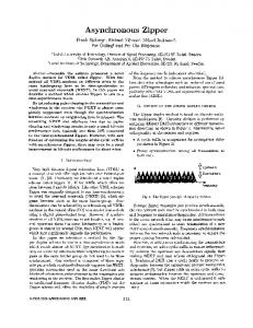
matching templates. Section IV describes the details of our asynchronous matrix-vector multiplier, including a discussion of the four different controllers adopted for comparison. The performance-energy comparison of the designs is presented in Section V, followed by some conclusions given in Section VI. II. BACKGROUND An asynchronous circuit typically consists of a set of functional components that locally communicate using a set of handshaking protocols across channels. A plethora of asynchronous design styles exists which vary the size of functional components, the parallelism in the handshaking protocols, the data encoding across the channels, and the degree of timing assumptions needed to ensure correctness. In this section, we review asynchronous channels, as well as linear and nonlinear pipeline architectures, including related control circuit functionality and timing constraints. A. Channels: bundled-data vs 1-of-N rail A communication channel is a bundle of wires between a sender and receiver and a protocol for communicating information discretized into tokens (representing data, control, or a mixture). In a bundled-data channel, as illustrated in Fig. 1(a), tokens are encoded using one wire per bit of information, a request line (Req) is used to tell the receiver when the token is valid, and an acknowledge line (Ack) is used to tell the sender when the token has been received. In other words, the data is bundled with the request line. In a 1-of-N channel, as illustrated in Fig. 1(b), on the other hand, N wires are used to encode log2 N bits and no request line is needed. In particular, a widely used form of 1-of-N encoding is 1-of-2 (also called dual-rail encoding) in which two wires are used to encode one bit of information. In 1-of-N encoding, also called onehot encoding, the validity of the data is encoded in the values of the N wires; all zeros indicate that the bundle of wires is reset and holds no token. Both two and four-phase handshaking protocols exist across communication channels. In this paper, we restrict ourselves to four-phase protocols in which after the sender sends the
Fig. 2.
Bundled-data linear pipeline.
data (the first phase), the acknowledgement is asserted by the receiver (the second phase). Next, the sender resets the data (the third phase), followed by the receiver resetting the acknowledgement (the fourth phase). If the acknowledgement is active low, it is often referred to as an enable (En). B. QDI versus bundled-data design styles One common asynchronous design style maintains quasidelay-insensitivity (QDI) within pipeline stages and delayinsensitivity (DI) communication between stages [9]. Within a pipeline stage, the delay of any gate can be arbitrary but some wire forks must be isochronic. Between pipeline stages, however, 1-of-N rail signaling is used to obtain complete insensitivity to variations in wire delay [11]. A recently proposed QDI/DI implementation style based on circuit templates has been developed for fine-grain nonlinear pipeline stages. These templates simplify micro-architecture design, remove much of the need for automated controller synthesis, and ease physical verification requirements [9]. A second common design style is bundled-data design [12]. Fig. 2 shows an example of bundled-data linear pipeline. Each stage communicates with its neighboring stages by left and right communication channels. A channel contains transmitting information (data) and control signals that synchronize communication between stages by a defined handshaking protocol. In contrast to the QDI design, since data and control are sent separately, several relative timing constraints must be verified to ensure correct data transmission. A pipeline stage consists of a standard synchronous datapath (DPU) in which a combination of a delay line and asynchronous control circuit (AC) controls an output flip-flop (FF). The setup and hold requirements on the flip-flop are often called bundling constraints. Additional setup and hold requirements on the conditional inputs (CIs) from the datapath to the asynchronous control may also exist. The controller is responsible for triggering the FF via the local clocks (lclk) and generating an output control token to communicate with the next pipeline stage. Compared to QDI/DI templates bundled-data design styles can be significantly smaller, can consume less energy at equal supply voltages, and have the ability to reuse synchronous design methodologies for datapath design [13]. The major disadvantage is that the methodology and tool support for analyzing and guaranteeing margins on all timing constraints is immature, yielding higher risk and longer design times. Another disadvantage is that the timing margin lengthens the latency of the pipeline which is often critical to system performance.
TECHNICAL REPORT CENG-2005-03
3
En1 En2 Fork
Req
P1
P3
Info
III. A SYNCHRONOUS C ONTROL C IRCUIT T EMPLATES Join
Info
P2
(a) Non-linear pipeline with fork
Fig. 3.
En Req1 Req2
P4
(b) Non-linear pipeline with join
Examples of nonlinear pipelines.
C. Control circuits for nonlinear pipelines Control circuits for nonlinear pipelines, such as forks and joins illustrated in Fig. 3, must handle the reading of multiple input channels and the writing of multiple output channels [9]. In addition, in both linear and nonlinear pipelines, more complicated behavior can occur when channels are conditionally read or written depending on the data on input control channels and/or the value of CIs from the datapath. One common conditionally writing output operation is a skip [9], in which based on the value of the CIs, the triggering of the FF and/or the generation of an output control token is suppressed. This is particularly useful for low power application. D. Performance metrics To compare among different synchronous/asynchronous designs, the following metrics are used to analyze the performance of bundled-data pipelines. I: Forward latency (F L) is defined as the delay of the request of the current stage to the request of the next stage. In other words, it indicates the evaluation time of the datapath. II: Overhead (OH) is defined as the delay beginning from the request of the next stage to the next request of the current stage. In other words, it is the overhead associated with resetting the control circuits. III: Cycle time (τ ) is defined to be the maximum delay from the processing of current token to the same processing of the next token. By definitions, the cycle time is the sum of F L and OH. In bundled-data pipeline design, the forward latency (FL) of the control is matched with the datapath delay to guarantee that data is stable before latching it in the next pipeline stage. Consequently, the forward latency is relatively fixed. The remaining part of the cycle time is the control overhead (OH) and thus, a control template that has smaller overhead will achieve higher throughput. The ideal synchronous design has zero overhead since each pipeline stage latches data simultaneously at every clock edge and thus it can use the whole cycle for evaluation i.e. τ = F L. In practice, however, synchronous designs must provide enough timing margin/overhead to compensate for clock skew and uncertainty in gate and wire delay.
The largest design challenge for bundled-data design is in the development of efficient control circuits. We address two major control circuit design challenges. First, due to the large control overhead, bundled-data designs are generally slower than their synchronous counterparts. The proposed control protocols reduce this overhead significantly. Second, most existing methodologies are limited to simple linear pipeline design and the adaptation to more complex control is generally difficult and error-prone. Furber [14] proposed circuits for simple linear pipelines. New true 4-phase circuits that better hide control overhead have also been developed and proposed by [10], [15]. Both of these works, however, do not address the design of more complicated control circuits required for nonlinear pipelines, such as forks, joins, splits and merges [12]. For these nonlinear pipelines, synthesis-based approaches using Burst-Mode Diagrams (BM) and/or Signal Transition Graphs (STG) are required [16]–[19]. These approaches, however, rely on the designer to produce correct and efficient specifications, which are often difficult and error-prone [20]. Initial efforts to automate this approach are presented in [21] and [22]. In this section, we propose to adopt and extend 1-of-N rail circuit templates developed for QDI circuits to design the control for bundled-data pipelines. These templates provide a unified block-level decomposition of complex control circuits where the implementation of each block can be easily manually derived from the overall specification. The templates greatly simplify the complex and error-prone process of complex control circuit design using STGs or BM machines. Additionally, the design of efficient templates would simplify the task of future synthesis tools to a mapping process that maps the designs to the target templates instead of performing logic synthesis in [21], [22]. We thus exploit both the low area and power of single-rail datapaths and the simplicity of a templatebased control design methodology. Specifically, we show how to adopt an existing QDI template called precharged full-buffer [9] to bundled-data pipelines, develop a new advanced true 4phase full-buffer template that better hides control overhead, and further optimize the T4PFB template into a zero-overhead T4PFB template which completely hides control overhead. A. PCFB template for bundled-data The adopted PCFB template for 1-of-N linear pipelines is shown in Fig. 4. Our template is different from the original PCFB in that the conditional inputs CIs can be single-rail and that the local clock signal(s) lclk(s) has no associated acknowledgement. There is one R gen block for each output rail Ri , as depicted in Fig. 4 (b). The local clock signal can be generated like any other Ri output or be generated via combinational logic with Ri ’s as inputs. The iLCD and iRCD blocks are inverting left and right completion sensing circuits [9]. The abstract protocol of this template is defined by the STG in Fig. 5. When a left token arrives (L+), the R gen dynamic logic blocks evaluate, generating a valid output token, the local clock will fire (∼ Ri −, Ri +), and simultaneously
TECHNICAL REPORT CENG-2005-03
4
aC
iLCD
C
iRCD
… …
…
R_gen
(a) PCFB circuit template for 1-of-N input and 1-of-M output channels Fig. 4.
N-stacks
…
(b) R_gen circuit for the ith output rail
PCFB template and a detailed circuit.
en R1e R2e R_t
R_f L_t
L_f R2e R1e en
Fig. 6.
R gen circuit of the PCFB fork stage.
Fig. 5. STG of the abstract PCFB protocol where each edge is labeled with its delay (# of gate delays).
the iLCD block detects the token arrival (ilcd−). Next, the iRCD block detects that right data is valid (ircd−), which causes the left enable to be deasserted (Le−), and the internal state to be reset (en−). Once the left data is reset (L−), the iLCD block detects that the data is null (ilcd+) and, together with the reset of enable, causes the left enable to be re-asserted (Le+). This completes the cycle for the left environment, allowing it to send a new token, even if the right environment is slow or stalled thereby avoiding a significant performance penalty [14] 1 . The right environment operates concurrently. After receiving valid data, the right environment will deassert the right enable (Re−), allowing the R gen blocks to precharge. This allows the right environment to reassert the right enable (Re+) and, simultaneously, the internal enable to be re-asserted (en+). This in turn allows the R gen 1 This property of full buffer [9] or fully-decoupled [14] that allows the left environment to reset immediately without waiting for the right environment to reset is well-suited to bundled-data pipeline design since bundled-data design usually involves a slow right environment associated with the datapath delay of the next pipeline stage.
blocks to re-evaluate in response to a new token. It is important to note that this STG is a description of the abstract protocol and, while useful to convey the level of parallelism and the timing assumptions inherent in the protocol, it is insufficient for the purposes of synthesizing control circuits. The principle reason is that it does not explicitly describe the functionality of the R gen blocks, which can be quite complex and difficult to specify using the STG (often involving OR causality) [23]. The STG also does not describe how the conditional inputs from the datapath can induce a skip. 1) Nonlinear PCFB pipelines: Fork stages need to wait for all output enable signals to set/reset before setting/resetting the output tokens. A solution, adopted from standard PCFB, is to insert a C-element to combine all output enable signals. If the number of fork stages is small, the C-element can be integrated into the R gen circuit, as illustrated in Fig. 6. Join stages need to wait for all input data to be set/reset before setting/resetting the input enable. One solution is to combine the iLCD of all input channels with a C-element to detect completion of all input data. An example of the OR of L1 and L2 dual-rail channels is shown in Fig. 7. If one of
TECHNICAL REPORT CENG-2005-03
5
iaC
~Le
Le
+
Re ilcd
Re rcd
to RCD
ilcd
rcd
ilcd
~Ri iLCD
RCD
~Lj ~L0…N-1
L0…N-1
lti
d CL
latch
ltj
Ri
d CIs
N-stacks
~R0…M-1
R0…M-1
R_gen
ltj CIs
Latch output (ltj) from other left channels
lclk
(a) T4PFB circuit template for many 1-of-N input channels and one 1-of-M output channels
Fig. 8.
T4PFB circuit template and detailed circuits.
L1_t L1_f L2_t L2_f (a) R_gen circuit implementing L1 OR L2
Fig. 7.
(b) Latch circuit for the jth input rail (left) and R_gen circuit for the ith output rail (right)
C
ilcd
(b) iLCD circuit
Circuits of the PCFB join stage.
the true rails of L1 or L2 is asserted, the true rail of R is asserted. However, both false rails of L1 and L2 need to be asserted to cause the false rail of R to be asserted. The iLCD circuit combines the completion detection of both input data (L1, L2) with a C-element shown in Fig. 7(b). Interestingly, this type of join causes significant timing problems with other pipeline design styles, such as PS0 [24], [25]. Supporting conditional reading and writing is only slightly more complex. To conditionally read a channel, the associated Le generation block generates a left enable only if a channel is read. To conditionally write a channel, the R gen block must conditionally evaluate and handshake with the right enable only when it evaluates. In particular, a skip can be implemented by triggering the evaluation of a separate output signal (not routed out of the controller) that acts like an M+1 output rail and immediately sending acknowledge back to the left environment without waiting for the right environment. 2) Timing and performance analysis: The original PCFB template is robust in that there are no internal timing assumptions on gate delays [26], i.e., it is quasi-delay-insensitive. Our adaptations, however, have setup and hold constraints on the conditional inputs, typical of bundled-data designs. Additionally, the local clock signal must have sufficient pulse width to transfer information across the flip-flops. In particular, the pulse width of the clock is the same as the pulse width of the R gen circuits if implemented as combinational logic of R signals. If it is implemented using an R gen circuit, the
Re PMOS transistor is optional. If removed, the pulse width reduces to the sum of the delays of the iRCD (ircd−), left enable (Le−), enable (en−), and R gen clock circuits. It is assumed that this pulse width is sufficient to latch the outputs, which is easily satisfied if the flip-flops are properly designed. A quantitative performance analysis is based on the following assumptions. First, the delay is calculated by counting latency in term of gate (unit) delays. The abstract STG shown in Fig. 5 illustrates the sequencing of events for a PCFB pipeline stage where each edge is labeled with the above delays. Second, the analysis is performed on a homogeneous linear pipeline assuming the completion sensing of each stage takes only one gate delay which is a reasonable assumption for a single input/output channel of up to four rails (a 1of4 channel). Third, the delay calculation includes the set (DLset ) and reset (DLreset ) delays of the delay line attached to the left request input of the controller as shown in Fig. 2. Thus, the performance analysis of PCFB template is as follows. F L = R+cur ⇒ R+next = DLset + (L+ ⇒ R+) = DLset + 2 OH = R+next ⇒ R+cur nextcycle = (R+next ⇒ Le−)+ (Le− ⇒ L− ⇒ ilcd+ ⇒ Le+ ⇒ R+cur nextcycle ) = DLreset + 10 τ = F L + OH = DLset + DLreset + 12 The main disadvantage of this protocol is its large overhead. The second drawback is that the forward latency contains only the set phase of the delay line. This means that the reset phase of the delay line must be minimized, motivating the use of asymmetric delay lines [27]. Lastly, the combinational logic necessary to determine R outputs is limited to what can be implemented in a single R gen gate.
TECHNICAL REPORT CENG-2005-03
6
Fig. 10.
The modified Le gen circuit.
R_gen circuit Fig. 9. STG of the abstract T4PFB protocol where gray edges represent timing constraints and dashed edges indicate ordering maintained by the environment.
B. T4PFB templates for bundled-data To reduce control overhead, we propose a new circuit template that follows the true 4-phase handshaking protocol. In particular, our template, as illustrated in Fig. 8, differs from PCFB template in that it waits until the left token arrives, the left enable to be sent back, and the left token to reset, before generating a right token. In other words, the T4PFB explicitly decouples the control by forcing the handshaking with the left environment to essentially finish before beginning to communicate with the right environment. Consequently, the forward latency includes both phases of the delay line, enabling the use of either asymmetric or symmetric delay lines and facilitating lower control overhead. The STG of the abstract protocol for this template is shown in Fig. 9. When a left token arrives (L+), the iLCD detects that token is valid (ilcd−) and opens the dynamic latches allowing the token to propagate (lt+). At the same time, the inverting asymmetric C-element (iaC) deasserts the left enable (∼ Le+, Le−). While waiting for the left token to reset, the CL block can perform precomputation with control tokens from other input channels as needed (d+). Once the left token is reset, the iLCD detects that the token is reset (ilcd+) and isolates the latches from the arrival of new tokens. At this step, the iLCD triggers two concurrent operations. First, the iLCD triggers the functional blocks to evaluate and generate a right token (∼ R−, R+). After a right token is generated, the right token validity is detected (rcd+), causing the internal signals to reset (lt−, d−) preparing to accept a new token. Second, the iLCD also triggers the left enable to re-assert (∼ Le−, Le+) acknowledging the left environment. This completes the left environment protocol, allowing the left environment to send a new token. Concurrently with the left environment, when the right token is consumed, the right enable is deasserted (Re−)
Fig. 11.
Circuits of the T4PFB fork stage.
and the right token is reset to null (∼ R+, R−). Then, the right environment will re-assert the right enable (Re+) thereby making the circuit ready to accept a new input token. The significant overhead reduction comes from concurrent assertion of a right token (R+) and a left enable (Le+) enabling the left environment to latch a new data as soon as it receives the left enable signal Le+. We can also improve performance by allowing the right token to reset (R−) concurrently with the resetting of the left enable (Le−). This is implemented with two parallel transistors connected in the PMOS stack shown in Fig. 10. A transistor connected to the input signal rcd enables Le− in the first cycle after global reset. A transistor connected to the Re input signal drives Le− in the remaining cycles without waiting for rcd−, thereby reducing the delay in the longest cycle i.e. Le− → L− → R+ → Re− → Le− from 12 to 10 gate delays (not including the delay line delay). However, this additional concurrency introduces timing margins TM7 discussed later in timing analysis section. A more robust but lower performance version of T4PFB template with no concurrency between R and Le is discussed in [28]. Compared to the PCFB template, the functional block (R gen) has the same complexity of NMOS networks, but has one less PMOS transistor. However, the T4PFB template provides an additional CL block that allows precomputation while waiting for the left environment to reset. This may further simplify the NMOS network in the R gen block. Implementation and timing issues of conditional input/output signals to/from datapath (CIs, lclk and skip) are the same as discussed in the PCFB template. 1) Nonlinear T4PFB pipelines: The same techniques discussed in Section III-A.1 are applicable to the design of T4PFB templates for fork and join stages. An example of a
TECHNICAL REPORT CENG-2005-03
7
3. Data reset timing margin (T M 3). To avoid re-evaluation of the R gen block with stale input data, after R gen is evaluated the output of the CL block should reset (d−) before a new arrival of ilcd (ilcd+). Thus, we have that
Fig. 12.
R gen and CL circuit (in dash boxes) of the T4PFB join stage.
fork stage implementing a copy of input tokens to two output stages is shown in Fig. 11. The Re1 and Re2 are connected directly to both PMOS and NMOS networks in the R gen circuit. An alternative is to combine Re1 and Re2 with a Celement before controlling the R gen circuits. An example of a nonlinear join stage implementing the OR of two dual-rail inputs, L1 and L2, is depicted in Fig. 12. The iLCD circuit for this template is depicted in Fig. 7(b). The OR functionality is precomputed within the CL block. The left CL block is asserted only when the false rails of lt0 f and lt1 f are asserted and the right CL block is asserted when either lt0 t or lt1 t is asserted. More complex nonlinear control circuits (e.g., merge and split) are derived in the same manner as their PCFB counterparts. 2) Timing and performance analysis: The T4PFB template has several easily-met timing assumptions that were needed to ensure high performance. These assumptions, identified by the gray ordering edges in the STG shown in Fig. 9, are now analyzed in detail. The first four timing assumptions are timing related to the validity of local data stored in the latches. The remaining three timing assumptions are due to the concurrent setting and resetting of R and Le. 1. Latch propagation timing margin (T M 1). The left token must be properly stored in the dynamic latch (lt+) before the data is reset by the left environment (∼ L+). In other words, we have the following timing constraint: T M 1 = (L+ ⇒∼ L+) − (L+ ⇒ lt+) where, (L+ ⇒∼ L+) = (L+ ⇒ Le− ⇒ L− ⇒∼ L+) = 6 + DLreset (L+ ⇒ lt+) = max(L+ ⇒ ilcd− ⇒ lt+, L+ ⇒∼ L− ⇒ lt+) =2 So, T M 1 = 4 + DLreset
2. Latch reset timing margin (T M 2). After the RCD initiates the reset of the latch, the latch should have enough time to reset (lt−) before the RCD changes its output (rcd−). Thus, we have that T M 2 = (rcd+ ⇒ rcd−) − (rcd+ ⇒ lt−) where, (rcd+ ⇒ rcd−) = 5 + DLset (rcd+ ⇒ lt−) = 1 So, T M 2 = 4 + DLset
T M 3 = (∼ R− ⇒ ilcd+) − (∼ R− ⇒ d−) where, (∼ R− ⇒ ilcd+) = 9 + DLset + DLreset (∼ R− ⇒ d−) = 4 So, T M 3 = 5 + DLset + DLreset
4. Data stable timing margin (T M 4) 2 . The output of the CL blocks need to be stable (d+) before the output of iLCD block is asserted (ilcd+) to prevent a glitch from CL block from causing a spurious evaluation of an R gen block. Thus, we have that T M 4 = (ilcd− ⇒ ilcd+) − (ilcd− ⇒ d+) where, (ilcd− ⇒ ilcd+) = 5 + DLreset (ilcd− ⇒ d+) = 3 So, T M 4 = 2 + DLreset
5. Output validity timing margin (T M 5). Since a right token (R+) and left enable (Le+) are generated concurrently, enough time must be given to ensure that the output validity is detected (rcd+) before a new token arrives and deasserts the left enable (∼ Le−). Thus, we have that T M 5 = (ilcd+ ⇒ ilcd−) − (ilcd+ ⇒ rcd+) where, (ilcd+ ⇒ ilcd−) = 5 + DLset (ilcd+ ⇒ rcd+) = 2 So, T M 5 = 3 + DLset
6. Left enable stable timing margin (T M 6). Since a right token (R+) and left enable (Le+) are generated at the same time, the left enable must be stable (∼ Le−) before the right enable is deasserted (Re−). T M 6 = (Re+ ⇒ Re−) − (Re+ ⇒∼ Le−) where, (Re+ ⇒ Re−) = 5 + DLset (Re+ ⇒∼ Le−) = 1 So, T M 6 = 4 + DLset
7. Left enable reset timing margin (T M 7). Since a right token (R−) and left enable (Le−) are reset at the same time, the left enable must be stable (∼ Le+) before the right enable is asserted (Re+). T M 7 = (Re− ⇒ Re+) − (Re− ⇒∼ Le+) where, (Re− ⇒ Re+) = 5 + DLreset (Re+ ⇒∼ Le+) = 1 So, T M 7 = 4 + DLreset
2 Note
that if the CL block is glitch free, this constraint can be ignored.
TECHNICAL REPORT CENG-2005-03
Fig. 14.
The STG of the zero overhead T4PFB template.
This analysis indicates that the worst timing margin is three or more gate delays not including the delay line 3 . These are, thus, easily met with proper transistor sizing. Timing constraints of the conditional inputs and the local clock (CIs, lclk) are the same as PCFB’s and also easily met with transistor sizing and delay line design. The same performance metrics discussed in Section III-A.2 are derived for the proposed T4PFB template as follows. F L = R+cur ⇒ R+next = DLset + (L+ ⇒ ilcd− ⇒ Le−)+ (Le− ⇒ L− ⇒ ilcd+ ⇒ R+) = DLset + DLreset + 8 OH = R+next ⇒ R+cur nextcycle = R+next ⇒ Le+ ⇒ R+cur nextcycle =2 τ = F L + OH = DLset + DLreset + 10 The analysis shows that the overhead of T4PFB is independent of the length of the delay line, supporting the use of both asymmetric or symmetric delay line. Moreover compared to PCFB, the control overhead is smaller by 8 + DLreset gate delays, a significant improvement. C. Zero overhead T4PFB templates for bundled-data The concurrent assertion of the right token (R+) and the left enable (Le+) in the T4PFB control template demonstrates that part of control overhead can be hidden in the forward latency. However, the control overhead still consists of the 2 gate delay penalty associated with the right token generation of the previous pipeline stage (from Le+ to R+). A new protocol called zero-overhead T4PFB extends the original T4PFB by hiding the remaining overhead. In particular, by adding two gate delays in the forward path of the T4PFB controller, the new template illustrated in Fig. 13 achieves zero overhead. The STG of the abstract protocol is shown in Fig. 14. This control protocol functions similar to the T4PFB control protocol as follows. First, a left token arrives, is acknowledged, and then reset (L+, Le−, and L−). After this reset, an internal 3T M 4
is generally easy to ignore
8
token and a right token (R+) are generated concurrently with the assertion of the left enable (Le+). Notice that the assertion of the left enable (Le+) occurs two gate delays earlier than the generation of the right token (R+) (assuming the right enable was previously asserted (Re+) before the arrival of the right token (R+)). This enables both current and previous pipeline stages to latch data at the same time achieving zero overhead. 1) Nonlinear pipeline: The zero overhead template can be divided into two blocks: a Block1 with R gen1 and a Block2 with R gen2 as shown in Fig. 13 and 15(a). Nonlinear pipeline functionality can be implemented in either the R gen1 and R gen2 blocks. However, it is more robust to implement the complex behavior in R gen2 block since the forward latency may include the latency of R gen1 block which can cause a setup constraint violation. Thus, the R gen1 block is generally used to implement a simple buffer and the R gen2 block is used to handle nonlinear behaviors. Fig. 15 illustrates several suggested implementations of nonlinear pipeline stages. 2) Timing and Performance analysis: Since this template is adapted from T4PFB control template, timing assumptions listed for the T4PFB template are also applied to this template except that T M 2, T M 6 and T M 7 are more stringent since there is no delay-line delay involved in the equations. The performance metrics of the zero-overhead T4PFB template are derived from the STG shown in Fig. 14 as follows. F L = R+cur ⇒ R+next = DLset + (L+ ⇒ Le−)+ (Le− ⇒ L− ⇒ M + ⇒ R+) = DLset + DLreset + 10 OH = R+next ⇒ R+cur nextcycle =0 τ = F L + OH = DLset + DLreset + 10 Note that while the hold time in the datapath of this template is more critical than that in the PCFB and T4PFB approaches, it is no more stringent than that in the synchronous counterpart since both designs are zero-overhead pipelines. Additionally, by adding more forward latency, negativeoverhead pipeline in which more than one data is executed in a pipeline stage can be derived with more aggressive constraints on the hold time.
D. Comparison of control templates The section compares and contrasts the advantages and disadvantages of three different proposed control protocols: PCFB, T4PFB and ZO T4PFB. The following equations list the flip-flop’s setup time (Ts ) and hold time (Th ) requirements of a bundled-data pipeline design where Dmin and Dmax are the minimum and maximum delay of the datapath, Dclk to q is the clock to output delay of the flip-flop and OH is the overhead of asynchronous controller.
TECHNICAL REPORT CENG-2005-03
9
Le_gen
!
iLCD
RCD
N-stacks
…
…
…
RCD
latch
CL
…
R_gen1
…
R_gen2
…
(a) Zero-overhead T4PFB circuit template for many
(b) R_gen circuit for the ith output rail (left) and
Le_gen circuit (right)
1-of-N input channels and one 1-of-M output channels
Fig. 13.
Zero-overhead T4PFB template and detailed circuit implementation.
Block1 (buf)
Block2 (buf)
Block1 (buf)
(a) Buffer stage
Block1 (buf)
c
(b) Fork stage
Block1 (buf)
Block2 (join)
Block1 (buf)
Block2 (split)
Block1 (buf) (d) Split stage
(c) Join stage Fig. 15.
Block2 (fork)
Examples of nonlinear pipeline stages.
Ts < τ − Dmax Th < Dmin + Dclk to q + OH
(1) (2)
Eq. (1) states that the setup time (Ts ) must be less than the cycle time (τ ) minus maximum delay of the datapath (Dmax ) and Eq. (2) states that the hold time (Th ) must be less than accumulated delay of the minimum delay of the datapath (Dmin ), the clock to output delay (Dclk to q ) and the control overhead delay (OH). Notice that hold time constraint is generally easy to meet particularly if the overhead delay is positive. Table I compares the performance, and robustness spectrum of the three proposed protocols. The PCFB controller offers the best robustness, area and energy, but suffers from the largest overhead yielding the worst performance among the others. The T4PFB controller offers relatively high performance with reasonable timing assumptions in both the control and datapath. The last controller, ZO T4PFB, is the most aggressive controller and achieves the highest speed at the cost of the most critical timing margins. Table II presents concrete comparisons of these control templates using identical datapath delays that fix the forward
latency of the control circuit 4 . The comparisons assume that each template has equal setup time such that the cycle time dictates the performance of the design. The examples show that for shallow to medium size datapath, the T4PFB and ZO T4PFB can achieve better throughput than the PCFB template. For example, if the datapath length is 10 gate delays, the ZO T4PFB template is the fastest template running with the cycle time of 12 gate delays followed by the T4PFB template running at 14 gate delays and the PCFB template runing at 22 gate delays. Notice that for the shallow pipelines of 2 gate delays, the T4PFB and ZO T4PFB templates can have longer overall latency compared to the PCFB template due to long control latency. For medium-grain pipelines, however, we do not expect that the controller latency to be the limiting factor since this latency is used together with the delay line delay to match the datapath delay.
4 The DL reset of PCFB template is assumed to be 2 gate delays and DLset and DLreset of both T4PFB templates are assumed to be equal.
TECHNICAL REPORT CENG-2005-03
Protocols PCFB T4PFB ZO T4PFB
10
FL gate delays DLset + 2 DLset + DLreset + 8 DLset + DLreset + 10
OH gate delays DLreset + 10 2 0
τ gate delays DLset + DLreset + 12 DLset + DLreset + 10 DLset + DLreset + 10
area & energy 1X 2X 3X
TABLE I C OMPARISON OF THE PCFB, T4PFB AND ZO T4PFB CONTROLLERS , INCLUDING FORWARD LATENCY,
Margin (gate delays) control datapath (hold) QDI DLreset + 10 3 2 3 0
OVERHEAD , CYCLE TIME , AREA , ENERGY AND
DEGREE OF TIMING ASSUMPTION .
Datapath delay + setup time 2 10 20 40
FL 2 10 20 40
PCFB OH 12 12 12 12
τ 14 22 32 52
FL 8 12 20 40
T4PFB OH 2 2 2 2
ZO FL 10 12 20 40
τ 10 14 22 42
T4PFB OH τ 0 10 0 12 0 20 0 40
TABLE II C OMPARISON OF THE PCFB, T4PFB AND ZO T4PFB CONTROLLERS WITH IDENTICAL VARIOUS DATAPATH DELAY OF 2, 10, 20 AND 40 GATE DELAYS .
Sel LD0
start
d0
ADLC NR0
LD1
d1
ADLC
done
NR1
start
LDn
dn
ADLC*
(a) Speculative asymmetric delay matching template (b) ADLC circuit implementation Sel LD0
start
d0
SDLC
NR0
LD1
d1
done
SDLC NR1
dn
LDn
SDLC*
(c) Speculative symmetric delay matching template Fig. 16.
Speculative delay matching templates.
(d) SDLC circuit implementation
TECHNICAL REPORT CENG-2005-03
E. Speculative Delay Matching Templates A delay matching element (delay line) is combinational logic whose propagation delay is matched with the worst-case logic delay of some associated block of logic. Generally, a delay line is implemented by replicating portions of the block’s critical path. To take advantages of average performance, a more complicated delay line design based on speculative completion sensing [29] is adopted. The original speculative delay line proposed in [29] uses multiplexors to select among several independent delay lines, thus wasting power and area. Kim et. al. [8] proposed a more compact delay line by reusing previous delay elements to generate the next larger matched delay. However, in their design the input signal still needlessly propagates through the entire delay line independent of the data value, thereby wasting power. We propose two novel speculative delay matching templates that are both compact and power saving: one for an asymmetric delay line and one for a symmetric delay line. Our templates are adapted from [8] but replace the multiplexors with delay line controllers, one per delay element, as shown in Fig. 16. Each controller functions similarly to an asynchronous split in that its input signal is routed to one of its output signals based on the select control lines. If the select lines indicate that target delay is obtained, the controller generates the done signal by routing the input to LDi . Otherwise, it propagates the input signal to the next delay element via N Ri . Since the input signal stops at the target delay element, power is significantly reduced. 1) Asymmetric delay line templates: The asymmetric delay line is depicted in Fig. 16(a). When used with the PCFB control template, the set phase of the delay line is matched with the worst-case delay of the logic and the reset phase of the delay line is strictly overhead. The operation begins with the set phase. When a start signal arrives (start+), it propagates to the first asymmetric delay element (ADL) asserting a delayed signal (d0 +). This delayed signal (d0 +) and the select lines (Sel) are input signals of an asymmetric controller (ADLC) whose implementation is shown in Fig. 16(b). This controller decides to assert either a local done signal (LD0 +) or the next request signal (N R0 +). If one of local done signals (LDi +) is fired, a done signal (done+) is generated finishing the set phase. Otherwise, a next request signal (N Ri +) activates the next delay element. Note that the last controller (ADLC∗) is not required and generates only a local done signal (LDn +). The reset phase begins when the start signal is reset (start−). It causes a done signal to reset quickly (done−) (2 gate delays) bypassing all delay elements with an AND gate. Simultaneously, the start signal actively resets all delay elements and controllers. Two timing constraints associated with the delay line must be satisfied. First, the select lines of each controller must be setup and valid before its associated delayed signal (di +) arrives, referred to as a select line setup constraint, to avoid a wrong routing decision. Second, all internal signals must be reset before the next start signal arrives, referred to as the delay line reset constraint.
11
2) Symmetric delay line templates: The symmetric delay line depicted in Fig. 16(c) and (d) utilizes both set and reset phases to match the worst-case logic delay. It is well-suited to the T4PFB control protocol since it transfers data to the next stage after passing throughout both set and reset phases of the delay line. There are two timing constraints associated with the symmetric delay line. First, the select line setup constraint described for the asymmetric delay line also applies to the symmetric delay line. Notice, however, that this setup constraint is more stringent than in the asymmetric delay line case because the matched delay elements are half as long. In addition, the select lines must be stable until after the end of reset phase, referred to as select line hold constraint. Satisfying both of these constraints, however, is significantly easier than satisfying the reset constraint of the asymmetric delay line. In particular, the lack of the reset constraint allows us to eliminate the final AND gate and alleviates the heavy load of the start signal in the SDLC controller shown in Fig. 16(a). The symmetric delay line is also approximately half the length of the asymmetric delay line, saving both area and power. These advantages makes the use of symmetric template very attractive. 3) Power-efficient asymmetric delay line: It is also interesting to note that a power-efficient asymmetric delay line can be constructed using a combination of a symmetric delay line and a D-element [30], [31]. A simple example of this delay line is illustrated in Fig. 17(a) 5 . The D-element operates as follows. After receiving a left request, it completes a full handshake on the right environment before acknowledging the left environment, enabling the use of a symmetric delay line on its right environment. In the reset phase, the D-element shown in Fig. 17 (c) can reset in 4 gate delays. To compare this delay line with a standard one, the timing analysis of PCFB control template using this delay line is illustrated in Fig. 17 (b) and detailed as follows. F L = R+cur ⇒ R+next = DLset + DLreset + D − element delay + (L+ ⇒ R+) = DLset + DLreset + 8 OH = R+next ⇒ R+cur nextcycle = P CF BOH1 + P CF BOH2 + D − elementreset = 14 τ = F L + OH = DLset + DLreset + 22 The analysis shows that the forward latency includes both phases of the delay line plus a small delay from the D-element (6 gate delays). Additionally, the overhead is independent of the delay line delay but still large due to the combined overhead from PCFB control (10 gate delays) and the reset delay from the D-element (4 gate delays). Compared to the standard asymmetric delay line, it is obvious that this delay line can save both area and power approximately by half. 5 The SDL unit in the Fig. 17(a) can be implemented to support more complex delay line of such symmetric speculative matching template.
TECHNICAL REPORT CENG-2005-03
12
D-element (a)
(b)
(c)
Fig. 17. (a) an example of power-efficient asymmetric delay line. (b) STG of D-element using in bundled-data pipeline. (c) A speed independent D-element implementation.
However, due to large forward latency, this delay line can only support a pipeline stage with the forward latency larger than eight. Thus, the standard asymmetric delay line is more suitable to smaller pipeline stages. IV. M ATRIX - VECTOR M ULTIPLICATION A RCHITECTURE In this section, we review matrix multiplication operation and discuss our proposed architecture in detail. A. Matrix-vector multiplication The matrix-vector specification that we are implementing can be expressed as follows: y0 a a a a x0 y1 c f −f −c x1 = y2 a −a −a a x2 y3 f −c c −f x3 (a ∗ x0) + (a ∗ x1) + (a ∗ x2) + (a ∗ x3) (c ∗ x0) + (f ∗ x1) − (f ∗ x2) − (c ∗ x3) = (a ∗ x0) − (a ∗ x1) − (a ∗ x2) + (a ∗ x3) (f ∗ x0) − (c ∗ x1) + (c ∗ x2) − (f ∗ x3) where a, c, and f are constant coefficients 6 . B. Asynchronous pipelined architecture: an overview At the algorithmic level, we adopt the basic strategy of implementing each matrix vector multiplication in four iterations, one per column of the matrix. In iteration i, the ith column is multiplied by the ith element of X. This involves multiplying an input Xi with three different coefficients and optionally inverting the result, thereby motivating the use of three distinct hardwired multipliers. The results of each iteration is stored in four distinct accumulators whose results are written to Y after the fourth iteration and then reset in preparation of the next input vector X. 6 a = 2−2 + 2−4 + 2−5 + 2−7 + 2−9 ≈ 0.35, c = 2−1 + 2−5 + 2−7 + 2−10 ≈ 0.46 and f = 2−3 + 2−4 + 2−8 + 2−14 ≈ 0.19
At the architectural level, we propose the novel five stage pipelined architecture shown in Fig. 18. The upper portion (highlighted in gray) of the picture shows asynchronous controllers communicated with the datapath and other controllers using four-phase handshaking signals rather than a global clock. To obtain low-power, the datapath is implemented using single-rail static logic. Numerous power optimizations taking advantages of small-valued input statistics are applied. The general idea is to dynamically deactivate groups of bit-slices that contain only sign extension bits (SEBs). The multipliers and accumulators in the datapath consist of groups of partitioned bit-slices that are selectively activated by mask control signals. In particular, the MASK and ZD units respectively identify bit-slices of input data that contains non-SEBs and detects the special case in which the data is zero. The mask signals (m(·)) are used to deactivate nonrequired SEBs by forcing them to zero via the input ANDing logic and are sent to control delay matching units in multiplier stage (containing the matched delay lines). Additionally, the same mask signals when latched (m0 ) are ORed with their previously registered versions (m00 ). The resulting mask signals (ORed m) identify the bit-slices of the accumulators that contain non-SEBs and control delay matching units in accumulators stage. Notice that because the input data is fed into multiple multipliers, the delay matching unit is shared over multiple multipliers and accumulators, thereby making its overhead a small percentage of the overall design. In the special case that the data is zero-valued, the ZD unit asserts a zero detect signal and sends it to the controllers to disable the entire computations. Additionally, the Partial Sign Bit Recovery (PSBR) logic extends the sign bit of newly activated bitslices in the accumulator to ensure that both inputs to the accumulator have the same number of activated bit-slices. Lastly, the Full Sign Bit Recovery (FSBR) logic recovers the suppressed zero bits of accumulators results to attain the correct final results. In the following sections, each pipeline stage is discussed in detail.
TECHNICAL REPORT CENG-2005-03
13
3 - 4
.
D
. .
. -
.
- 4 D
D
Speculative delay line
.
Speculative delay line 5 657/
5 657/
! "# $
5
.
D
.
/
5
.
3
5
. 5/ 5
/ - 4 .
-/
5 ’’
’’
)
*
.
-/
+
- 4
D
’’’
5 ’ 0
% &
’
’’
’
’’
’ . ) * + . -/ )
* , -/
& '( .
’
“ ”
-/
“ ” “ ”
+
# $
1 !
# $
1 !
# $
12!
# $
’’ “ ”
“ ”
’
, -
“ ”
’’
“ ”
’
“ ”
Fig. 18.
1 !
’’
“ ”
Matrix multiplication with a 5 stage asynchronous pipeline.
As mentioned earlier, it is not necessary to perform multiply-accumulated operations with zero-valued data since the result would remain the same. To save power consumption, zero data is detected and then stalled at this stage and only non-zero data are forwarded to the next stage. If the input data is zero (x = 0), the ZD unit asserts a zero detect signal. When the controller (Zd Ctr) detects that the zero detect signal is asserted, it gates a local clock signal (zd nz) thereby stalling the zero-input data. The controller also communicates with the controller for the next pipeline stage (Mul Ctr) using a dual rail channel called zd. If the input data is zero it asserts zd z. Otherwise, it asserts zd nz. The controller is implemented similarly to an asynchronous spilt cell with the zero detect signal acting as the select control channel. Additionally, regardless of the input data, the controller asserts an extra rail zd always to latch the zero detect signal for the next stage. The zd always is implemented by simply ORing zd z and zd nz. The details of our implementation are illustrated in Fig. 24(a). Note that for correct operation the zero detect signal must be valid before the bundled-data delayed signal matched with ZD logic becomes stable. D. (Hardwired) multiplier stage In this stage, a non-zero data from zero detection stage is multiplied with three constant matrix coefficients simultaneously. The implementation details are discussed below. 1) Bit-slice partitioning multipliers: Ideally, we might like to selectively activate only the effective non-zero bits. However, this would require control logic for every bit whose
Input (x)
MSB
C. Zero detection stage Bit Index
: 15 14
13
m(3)
Fig. 19.
12
11
10
9
m(2)
8
7
6
15
LSB 14
13
12
11
10
9
8
7
6
m(1)
Mask signals generation unit based on static logic.
overhead would be difficult to overcome. Thus, it is important to organize the activated bits into bit-slices and optimize the number of bit-slices that can be activated taking into account the overhead of the control logic. To this end, we performed bit-level simulations of well-known image sequences that showed that a zero detect flag along with 3-bit mask signals (m(3), m(2), and m(1)) for DCT yielded reductions in bitactivity within 10% from the optimal. Our proposed mask generation unit yields a longest path of about 4 gate delays illustrated in Fig. 19. Our fine-grain hardwired multiplier is based on a bitpartitioned carry-save multiplier, illustrated in Fig. 21. The carry-save multiplier’s critical path is mainly along the final, vector-merging adder, which we propose to implement as a bit-partitioned ripple carry adder for two reasons. First, ripple-
TECHNICAL REPORT CENG-2005-03
14
Input MSB
LSB 4
4FA
4
C2
4 !
"#$
! %!%
3
C1
4FA 4
6FA+2HA+2FA
3
10
Cout Output
&
Fig. 22.
Static fine-grain partitioned adder architecture. m''(3) m''(2) m''(1) t(18) m''(3) m''(2) m''(1) t(14) m''(3) m''(2) m''(1) t(11)
Fig. 20. Example of the proposed mechanism for sign bit extension in the multiplier array.
carry adders consume significantly lower power than faster (e.g., carry select or bypass) adders [32]. Secondly, while ripple-carry adders have relatively long worst-case delay, the bit-partitioning of the multiplier array (including the ripplecarry adder) leads to very good average case delay for this application. The staircase-patterned bit-slices, as illustrated by the dotted lines in Fig. 21, allow the adders to be dynamically configured for different input bit-widths. For example, if the first two bit-slices are activated, the multiplier behaves exactly as a typical multiplier that handles 9-bit inputs. There are two key aspects of the architecture that enable this type of reconfigurable bit-widths. The first is that when only the first two bit-slices are activated, the inputs to the second input bit-slice that emanate from the third input slice (i.e., that cross the dotted line) are forced to zero by the input ANDing logic. The second feature is the sign extension of the most right shifted input to the bit-slice boundary. Fig. 20 illustrates an example of the issue and our proposed solution. In particular, it illustrates the case when x0 À 9 is added to x0 À 7 when three bit-slices of x0 are activated, i.e., when bits b13 through b15 are forced to zero. The further right shifted input in this case is the x0 À 9 input and it must be sign extended two bits to the bit-slice boundary. Our solution is to add two MUXes that are controlled by the MASK logic. The MUXes output the x0 input bit except in the case when exactly three bit-slices are activated, in which case the MUXes output the sign extension bit (which in this case is the b12 bit of x0 ). As illustrated in Fig. 21, the number of MUXes needed is relatively small and they are typically not in the critical path Notice that some adders are eliminated in the area of the highest bit-slice due to the precomputation of their sign bits which enabling area and power saving even more. For example, the b14 of x0 À 5 is precomputed and forwarded to the next adder block 14 of the second row. 2) Speculative completion sensing circuit: Let us focus on the completion-sensing unit for our proposed hardwired multiplier. The critical path of the array depends on the carry chain of the ripple carry adder highlighted in Fig. 21. This path is partitioned into four bit-slices, as illustrated in Fig. 22. To sense the completion of this adder, we use our speculative delay matching template discussed earlier. The completionsensing unit is composed of four delay lines, matched to the four different bit-slices activated shown in Fig. 24(a). The mask signals m from the datapath are fed as the select lines
3FA
10
C0
MSB m''(3) m'(3)
MUX
t(18)-t(15) m''(2) m'(2)
3
Fig. 23.
LSB
SIGN
t(21)-t(19)
MUX 4
t(14)-t(12) m''(1) m'(1)
t(11)-t(0)
MUX 3
12
An example of partial sign bit recovery logic (PSBR b).
to control speculative delay line. 3) Multiplier controller: There are two types of matched delay lines used in the multiplier stage illustrated in Fig. 18, a short delay line (driven by zd z) that matches the computation delay associated with zero input data and a speculative delay line (driven by zd nz coupled with the mask signals) that matches the data-dependent multiplier computation. In both cases, the Mul Ctr generates mul z and mul nz signals using simple controllers illustrated in Fig. 24(a). By ORing both signals together, it generates the non-conditional mul always to trigger the FFs forwarding all control signals to the accumulator stage. For low-power, the mul nz signal latches the multiplier results only when the input data is non-zero. 4) Timing constraints: The setup constraint from the delay matching template is that the mask signals m must be valid before the first matched delay signal is valid. This ensures that the setup constraint for the next matched delay lines are also satisfied. In addition, the reset and hold constraints, for the asymmetric and symmetric delay templates must be satisfied. However, since there are no conditional inputs connected to the controller, there is no other timing constraints associated with the controller. E. Accumulator stage Our 4x4 matrix-vector multiplier consists of four accumulators each responsible for summing up the multiplication results for a different matrix row. For each computation, the accumulators accumulate four inputs corresponding to four matrix columns before asserting one output result. 1) Bit-slice partitioning accumulator: The bit-sliced architecture extends to the accumulator stage. By extending the bit-widths of each bit-slice by two in the accumulator stage, overflow/underflow is guaranteed not to occur during the four iterations of accumulation. In order to ensure that both input operands to each accumulator have the same number of
TECHNICAL REPORT CENG-2005-03
15
MSB
LSB
Input (x1) “
”
15 m(3)15 15 13
14
: : : b
Critical Path
13 14
13
12
MUX 13
15
15 14
18
17
16
12
12
12
14
:
13
13
12
11
m(2) 11
12
11
10
10
9
10
9
8
m(1) 8
9 8
7
7 6
7
6
6 5
5 4
5 4
3
4 2
3 2
1
0
>>9 >>7 >>5
Half Adder Full Adder
a s
14
14
13
11
11
11
12
10
10
10
9
11
10
9
8
8
7
7
9
6
8
6
7
5
4
6
5
5
6
4
4
5
3
3
3
2
4
2
3
9
8
7
15
14
13
12
11
10
9
8
7
6
5
4
1
3
15
14
13
12
11
10
9
8
7
6
5
4
3
2
1
1
0
>>4
0
2
1
>>2
0
2
1 bit-slice activated 2 bit-slices activated 3 bit-slices activated ALL bit-slices activated
Fig. 21. Proposed asynchronous fine-grained carry-save hardwired multiplier for 0. 35352*x1 , where 0.35352 is expressed as (2−9 *x1 ) + (2−7 *x1 ) + (2−5 *x1 ) + (2−4 *x1 )+ (2−2 *x1 ). ZD Ctr.
S
MUL Ctr.
B
D
OUT_S Ctr.
ACC Ctr. D
S
D
OUT_R Ctr.
B
D
B
S D
S
B
D D D
D D
ADLC/ SDLC
D
D
S ADLC/ SDLC
B
= R_gen w/ buffer function
S
= R_gen w/ split function
D
(a) Asynchronous controllers of five stage pipelines
ZD Ctr.
CG CG
Clock gating (CG)
MUL Ctr.
CG CG
ACC Ctr.
CG
OUT_S Ctr.
CLK
CG
OUT_R Ctr.
CG
CG
’ CG = Clock gating module ’
zd_detect’ is a latched signal of zd_detect. last’ is a latched signal of last.
(b) Gated clocking synchronous controllers of five stage pipelines
Fig. 24.
Controller alternatives: (a) asynchronous controller (b) synchronous controller.
activated bit-slices, both operands are partially sign extended by PSBRs. An example of PSBR b is shown in Fig. 23. The PSBR b first extracts the sign bit using its associated mask signal m00 for the current accumulation result. It then sign extends any newly activated bit-slices using a bank of MUXes that either pass the current bit or the extracted sign bit depending on the AND of the stored (m00 ) and current mask signals (m0 ). Notice that the least significant 12 bits needs no sign extension since they are never forced to zero. The mask signals associated with both input operands (m0 , m00 ) produce a new mask signals (ORed m) by ORing function carrying out the worst-case mask signals. The multiplexors M 0 selectively feed the proper multiplier results
to the first accumulator operand. The multiplexors M 1 route either previous accumulator results or zero data as initial input operand. To save power, the results are latches only if data is non-zero. We latch initial zero results at the beginning of each iteration by introducing multiplexors M 2. 2) Speculative completion sensing circuit: The critical path of the accumulators depends on the carry chain of the ripple carry adder. The speculative delay matching circuitry is therefore similar to that in multiplier with the mask signal ORed m acting as the select lines. 3) Accumulator controller: Similar to the multiplier stage, two delay lines (driven by mul nz and mul z) are matched to zero and non-zero data computations respectively. In addition, for each computation, the controller Acc Ctr asserts
TECHNICAL REPORT CENG-2005-03
the acc req signal at the end of each computation indicating that the results are ready. The acc latch nz f irst signal conditionally latches in zero data at the beginning of every computation and the intermediate results after every iteration in which the input data is non-zero (i.e. mul nz is asserted). The acc latch nz last signal updates the mask signals am0 with zero data at the end of every computation and the current mask (ORed m) after every iteration in which the input data is non-zero. Fig. 24(a) shows that all R gen blocks are implemented using conditional output control templates (spilt or skip). 4) Timing constraints: The delay line has the setup constraint that the mask signals must be valid (ORed m) before the first matched delay signal is valid. In addition, there is a setup constraint on the controller stating that the conditional signals (c0, c1) must be valid before a done signal from either delay line is asserted. F. Output storing and recovering stages The output storing stage latches the results from the accumulator stage at the end of each computation. The output recovering datapath (FSBR) then recovers the sign bits using its associated mask signals (m000 ) using logic similar to the PSBR blocks. Note that there is no timing constraints for either of these two controllers. G. Controller Alternatives Both synchronous and asynchronous controllers can be integrated with the same datapath. To fairly compare with our asynchronous designs, we implemented a gated-clocking synchronous controller with the same clocking conditions as the asynchronous design illustrated in Fig. 24(b). In addition, the controllers in Fig. 24(a) are implemented using PCFB, T4PFB and ZO T4PFB templates, yielding three different asynchronous designs for us to compare to. Both standard and power-efficient asymmetric delay lines are used with the PCFB-based design for comparison while symmetric delay lines are used with both T4PFB-based design. V. D ESIGN F LOW, E XPERIMENTAL R ESULTS AND C OMPARISONS Our designs use a hierarchical design flow shown in Fig. 25. First, after behavioral specification of the design is completely specified, an architectural specification is constructed by describing each block behaviorally using Verilog. In particular, the handshaking protocols between controller blocks are explicitly modeled. At this step, functional correctness of our architecture is verified by simulation. Next, each block is decomposed into gate-level where each gate is described behaviorally using Verilog. Dynamic timing analysis and optimization are performed that find the actual critical path in the datapath in term of gate delays. Additionally, timing analysis is also applied to the control to estimate average cycle time, forward latency and control overhead. Gate-level simulation of each block is performed to ensure correct operation. The next step is to map each gate in our library into its transistorlevel implementation. A set of transistor-level simulations is
16
performed to verify correctness and to ensure that all timing constraints are met. In particular, the delay line’s delay including setup and hold constraints are adjusted more precisely at this step. The final step is to hierarchically generate the layout. At this step, correctness and timing analysis are performed by extracting wire capacitance and thus considering the impact of interconnection delays. A. Postlayout timing validation All designs discussed above were laid out in Hynix 0.35µ CMOS technology. We simulated our designs on the extracted layout using Nanosim in typical environment i.e. 3.3V and 25o C. We validated timing constraints manually in postlayout and allowed all timing margins to be between 10% and 20%. Where necessary these margins were achieved by careful design of both the clock tree (for the synchronous design) and the delay lines (for the asynchronous designs). B. Energy and throughput comparisons Our first experiment compares asynchronous designs using the PCFB control with two different delay lines: one using a standard asymmetric delay line (P CF BASY M ) vs one using the power efficient delay line (P CF BSY M ). We simulated our designs by applying five different inputs which activates zero to all bit-slices. Table III displays average power, cycle time and energy per cycle. The result suggests that with comparable performance the design using P CF BSY M control yields up to 2% lower energy than one using P CF BASY M control. Nevertheless, since the controller contributes as little as 5% of the overall energy, the P CF BSY M controller yields up to 40% lower energy than the P CF BASY M controller. Thus, we choose the P CF BSY M control as the candidate design using PCFB control for the remaining comparisons. Next we compare three different asynchronous designs. Table IV illustrates the worst-case forward latency (F L), cycle time (τ ), and controller overhead (OH) of three designs for each type of inputs from zero to all bit-slices activated. The results suggests that the T4PFB controllers operate 17-35% faster than PCFB’s and the ZO T4PFB controllers run 1-9% faster than T4PFB’s. The result suggests the advantage of the ZO T4PFB template over the T4PFB template depends on the datapath length. For example, ZO T4PFB yields a 9% advantage for the zerodata case while it yields only 1% in case of all bit-slices activated. Thus, the ZO T4PFB template is more advantageous for designs with shallower datapaths. Furthermore, we simulated our synchronous counterpart by setting the cycle time to slightly more than the worst-case forward latency (to compensate for clock skew). In particular, the worst-case latency of the accumulators (acc bs3) is 19.8 ns and we set the synchronous cycle time to 20 ns. To quantify performance-power tradeoff, we setup 10 test cases as follows. The first 7 test cases, each having 20 input vectors, are simulated using Nanosim on the extracted layout. Of these, the first 5 test cases demonstrate average cycle time
TECHNICAL REPORT CENG-2005-03
17
Verification
Fig. 25.
Timing and performance analysis
Algorithmic verification
AlgorithmicDesign Design Algorithmic
Input statistics analysis
Functional verification
ArchitecturalDesign Design Architectural
Control handshaking design and analysis
Gate level Verification
GateLevel LevelDesign Design Gate
Dynamic timing analysis, performance analysis and optimization in gate delay
Timing verification w/o interconnection delay
TransistorLevel LevelDesign Design Transistor
Timing verification w/ interconnection delay
Layout Layout
Detailed timing and performance analysis and optimization
Hierarchical design flow.
Test Patterns zero bs1 bs2 bs3 bs4
P CF BASY M Power τ E/cye (mW) (ns) (pJ) 12.5 7.4 92.5 43.5 16.6 722 45.3 18.6 843 48.5 21.8 1055 46.4 23.9 1109
P CF BSY M Power τ E/cyc (ns) (ns) (ns) 13.1 7.1 92.3 42.7 16.8 715 43.9 18.8 825 47.8 21.7 1037 45.5 24 1092
% lower overall energy 0.16% 1% 2% 1.9% 1.5%
% lower controller energy 2-3% 10-19% 20-40% 19-38% 15-31%
TABLE III C OMPARISONS OF PCFB- BASED DESIGNS USING DIFFERENT ASYMMETRIC DELAY LINES .
Test Patterns zero bs1 bs2 bs3 bs4
FL (ns) 3.4 12.7 14.7 17.5 19.8
PCFB τ (ns) 7.1 16.8 18.8 21.7 24
OH (ns) 3.7 4.1 4.1 4.2 4.2
FL (ns) 4.1 12.6 14.6 17.6 19.8
τ (ns) 4.6 13.1 15 18.1 20.2
T4PFB OH (ns) 0.5 0.5 0.4 0.5 0.4
% faster (vs PCFB) 35% 22% 20% 17% 16%
FL (ns) 4.1 12.6 14.5 17.6 19.8
ZO T4PFB τ OH % faster (ns) (ns) (vs T4PFB) 4.2 0.1 8.7% 12.8 0.2 2.3% 14.7 0.2 2.0% 17.8 0.2 1.6% 20 0.2 1.3%
TABLE IV T IMING ANALYSIS OF THE PCFB- BASED , T4PFB- BASED AND ZO T4PFB- BASED DESIGNS , INCLUDING FORWARD LATENCY, TIME .
Test patterns zero bs1 bs2 bs3 bs4 mixed LB UB Flower Football Tennis
τ (ns) 20 20 20 20 20 20 20 20 20 20 20
SYNC E/cyc (pJ) 96 672 776 982 1016 830 568 826 705 705 705
Eτ 2 38 269 310 393 406 332 227 330 282 282 282
ASYNC-PCFB τ E/cyc Eτ 2 (ns) (pJ) 7.1 92 4.6 16.8 687 193 18.8 818 289 21.7 1037 488 24 1099 633 18.9 894 319 17.9 628 201 21.4 890 406 17.7 738 231 17.8 738 234 18.1 738 242
ASYNC-T4PFB τ E/cyc Eτ 2 (ns) (pJ) 4.6 90 1.9 13.1 673 115 15 786 177 18.1 962 313 20.2 1036 423 15 863 194 14.2 581 117 17.7 860 270 14.3 706 144 14.4 706 146 14.7 706 152
OVERHEAD , AND CYCLE
ASYNC-ZO T4PFB τ E/cyc Eτ 2 (ns) (pJ) 4.2 100 1.8 12.8 700 115 14.7 834 180 17.8 983 311 20 1047 417 14.8 870 191 14 611 119 17.5 875 268 14.0 740 145 14.1 740 147 14.4 740 153
TABLE V D ETAIL TIMING AND ENERGY ANALYSIS OF PCFB- AND T4PFB- BASED DESIGNS ( CONTROL AND DATAPATH ).
TECHNICAL REPORT CENG-2005-03
and energy comparison of zero data and 4 different bit-slices activated starting from zero data and then bit-slice one (bs1) to bit-slice four (bs4). Test case 6 is dedicated for mixed inputs activating all bit-slices. Test case 7 and 8 derive bounds of cycle time by arranging input sequences as follows. First, 20 inputs with the same bit-slice-activation distribution as real images are generated. Since the cycle time of a smaller bitslice is shorter than that of a longer bit-slice, the lower bound (LB) is simulated by ordering inputs from small to big valued data. Further, since our DCT initializes every four iterations and the accumulators state dictates global performance, the upper bound (UB) is arranged differently. By ordering from big to small-valued numbers within each computation, we obtain the worst-case cycle time for each iteration due to the worst-case bit-slice alignment in the accumulator stage. The last 3 test cases, derived from real images, have approximately seven million input vectors and are simulated using VerilogXL with back-annotated timing. The energy metrics for the last three test cases are estimated using a weighted average of the first 5 test cases. The experimental results are depicted in Table V. The first 2 columns for each design show the cycle time (τ ) and energy per cycle (E/cyc). The third column for each design enumerate the Eτ 2 [33] product compared to the synchronous design. The results lead to the following conclusions. First, since the identical datapath is applied to all designs, the energy differences are due to the difference in energy consumed by the controllers. The clock-gating synchronous controller consumes the least energy, followed by the asynchronous T4PFB controller, and followed by the asynchronous PCFB and ZO T4PFB which consume equivalent power. Additionally, the results show the effectiveness of bit-slice partitioning in that a smaller bit-slice consumes less energy than a larger one. In particular, a zero input data consumes far less energy than the others. Second, it is obvious that in the asynchronous designs a smaller bit-slice operates faster than a larger one. However, due to its large control overhead, the PCFB controller looses its speed advantage over the synchronous design when more than two bit-slices are active while the T4PFB controller is only slower when all bit-slices are active and the ZO T4PFB run at equal speed when all bit-slices are active. Furthermore, the results of the bound analysis suggests that compared to the synchronous design the cycle time of T4PFB and ZO T4PFB design are between 12-28% and 13-30% faster and the cycle time of the PCFB falls somewhere between 7% slower and 12% faster. Lastly, the simulation with the three real images indicates that the typical performance gain over synchronous design is approximately 30% for the ZO T4PFB-based design, 28% for the T4PFB-based design, and 11% for the PCFBbased design. Third, the asynchronous designs can tradeoff performance for low-power. Without voltage scaling, our designs gives 1130% higher performance with a 4-11% energy penalty. If the power supply is scaled, energy can be quadratically reduced. We adopt the Eτ 2 metric to quantify this advantage. The results show that, compared to the synchronous counterpart,
18
the PCFB-based design has a 18% Eτ 2 advantage while both ZO T4PFB and T4PFB-based designs have up to a 49% Eτ 2 advantage. VI. C ONCLUSION This paper demonstrates the use of an efficient asynchronous bundled-data pipeline design methodology on matrix-vector multiplication for DCTs. Architectural optimizations that takes advantage of zero and small-valued data, typical in DCT and IDCT, yield both high average performance and low power. Novel control circuit templates and data-dependent delay lines are proposed to create low overhead integrated control circuits capable of handling nonlinear pipelines and enabling high average throughput. Comparisons with comparable gated-clocking synchronous counterpart suggest that the proposed asynchronous design yields 30% higher throughput with negligible energy overhead and has a 49% better Eτ 2 metric. ACKNOWLEDGMENT This work was supported by a large-scale NSF ITR Award No. CCR-00-86036. The authors would like to thank Yunseuk Na for his help with the chip design. They also would like to thank Marcos Ferretti and Sangyun Kim for providing insightful discussions and Jay Moon for expert CAD tool support. Finally, they also would like to thank all the reviewers for their valuable comments. In particular, anonymous reviewer #2 suggested the power efficient implementation of the asymmetric delay line. R EFERENCES [1] K. Rao and P. Yip, Discrete Cosine Transform, Algorithm, Advantages, Applications. Academic Press, 1990. [2] A. Madisetti and A. W. Jr., “A 100 MHz 2-D DCT/IDCT processor for HDTV applications,” IEEE Transactions on CAS for Video Tech., vol. 5, no. 2, pp. 158–165, 1995. [3] S. Uramoto, Y. Inoue, A.Takabatake, J. Takeda, Y. Yamashita, M. Terane, and M. Yoshimoto, “A 100 MHz 2-D discrete cosine transform core processor,” IEEE Journal of Solid-State Circuits, vol. 36, pp. 492–499, April 1992. [4] T. Xanthopoulos and A. P. Chandrakasan, “A low-power IDCT macrocell for MPEG-2 MP@ML exploiting data distribution properties for minimal activity,” IEEE Journal of Solid-State Circuits, vol. 34, pp. 693–703, 1999. [5] R. Manohar, “Width-adaptive data word architectures,” in Advanced Research in VLSI, Mar. 2001, pp. 112–129. [6] R. Canal, A. Gonzalez, and J. Smith, “Very low power pipelines using significance compression,” in Proceedings of MICRO’33, Dec. 2000, pp. 181–190. [7] L. S. Nielsen and J. Sparsø, “Designing asynchronous circuits for lowpower: An IFIR filter bank for a digital hearing aid,” Proceedings of the IEEE, vol. 87, no. 2, pp. 268–281, Feb. 1999. [8] K. Kim, P. A. Beerel, and Y. Hong, “An asynchronous matrix-vector multiplier for discrete cosine transform,” in International Symposium on Low Power Electronics and Design, July 2000, pp. 256–261. [9] A. Lines, “Pipelined asynchronous circuits,” California Institute of Technology, Technical Report 1998.cs-tr-95-21, June, 1998. [10] A. M. G. Peeters, “Single-rail handshake circuits,” Ph.D. dissertation, Eindhoven University of Technology, June 1996. [11] T. Verhoeff, “Delay-insensitive codes—an overview,” Distributed Computing, vol. 3, no. 1, pp. 1–8, 1988. [12] I. E. Sutherland, “Micropipelines,” Communications of the ACM, vol. 32, no. 6, pp. 720–738, June 1989. [13] S. Tugsinavisut, S. Jirayucharoensak, and P. A. Beerel, “An asynchronous pipeline comparisions with appication to DCT matrix-vector multiplication,” in Proc. International Symposium on Circuits and Systems, May 2003, p. 1098.
TECHNICAL REPORT CENG-2005-03
[14] S. B. Furber and P. Day, “Four-phase micropipeline latch control circuits,” IEEE Transactions on VLSI Systems, vol. 4, no. 2, pp. 247– 253, June 1996. [15] C. Farnsworth, D. A. Edwards, J. Liu, and S. S. Sikand, “A hybrid asynchronous system design environment,” in Asynchronous Design Methodologies. IEEE Computer Society Press, May 1995, pp. 91–98. [16] T.-A. Chu, “Synthesis of self-timed VLSI circuits from graph-theoretic specifications,” Ph.D. dissertation, MIT Laboratory for Computer Science, June 1987. [17] R. M. Fuhrer, S. M. Nowick, M. Theobald, N. K. Jha, B. Lin, and L. Plana, “Minimalist: An environment for the synthesis, verification and testability of burst-mode asynchronous machines,” Columbia University, NY, Tech. Rep. TR CUCS-020-99, July 1999. [18] J. Cortadella, M. Kishinevsky, A. Kondratyev, L. Lavagno, and A. Yakovlev, “Petrify: a tool for manipulating concurrent specifications and synthesis of asynchronous controllers,” IEICE Transactions on Information and Systems, vol. E80-D, no. 3, pp. 315–325, Mar. 1997. Available: http://www.lsi.upc.es/˜jordic/petrify/refs/ [19] J. Cortadella and R. M. Badia, “An asynchronous architecture model for behavioral synthesis,” in Proc. European Conference on Design Automation (EDAC). IEEE Computer Society Press, 1992, pp. 307– 311. [20] K. Y. Yun, P. A. Beerel, V. Vakilotojar, A. E. Dooply, and J. Arceo, “The design and verification of a high-performance low-control-overhead asynchronous differential equation solver,” IEEE Transactions on VLSI Systems, vol. 6, no. 4, pp. 643–655, Dec. 1998. [21] A. Yakovlev, A. Koelmans, and L. Lavagno, “High-level modeling and design of asynchronous interface logic,” IEEE Design & Test of Computers, vol. 12, no. 1, pp. 32–40, Spring 1995. [22] M. Theobald and S. M. Nowick, “Transformations for the synthesis and optimization of asynchronous distributed control,” in Proc. ACM/IEEE Design Automation Conference, June 2001. [23] A. Yakovlev, M. Kishinevsky, A. Kondratyev, L. Lavagno, and M. Pietkiewicz-Koutny, “On the models for asynchronous circuit behaviour with OR causality,” Formal Methods in System Design, vol. 9, no. 3, pp. 189–233, 1996. [24] T. E. Williams, “Self-timed rings and their application to division,” Ph.D. dissertation, Stanford University, June 1991. [25] R. Ozdag and P. Beerel, “High-speed QDI asynchronous pipelines,” in Proc. International Symposium on Advanced Research in Asynchronous Circuits and Systems, Apr. 2002, pp. 13–22. [26] A. J. Martin, “The limitations to delay-insensitivity in asynchronous circuits,” in Advanced Research in VLSI, W. J. Dally, Ed. MIT Press, 1990, pp. 263–278. [27] C. Seitz, “System timing,” in Introduction to VLSI Systems, C. A. Mead and L. A. Conway, Eds. Addison-Wesley, 1980, ch. 7. [28] S. Tugsinavisut and P. A. Beerel, “Control circuit templates for asynchronous bundled-data pipelines,” in Proc. Design, Automation and Test in Europe (DATE), Mar. 2002, pp. 361–364. [29] S. M. Nowick, “Design of a low-latency asynchronous adder using speculative completion,” IEE Proceedings, Computers and Digital Techniques, vol. 143, no. 5, pp. 301–307, Sept. 1996. [30] A. J. Martin, “Programming in VLSI: From communicating processes to delay-insensitive circuits,” in Developments in Concurrency and Communication, ser. UT Year of Programming Series, C. A. R. Hoare, Ed. Addison-Wesley, 1990, pp. 1–64. [31] Y. Bystrov, D. Shang, F. Xia, and A. Yakovlev, “Self-timed and speed independent latch circuits,” in 6th UK Asynchronous Forum, July 1999. [32] A. P. Chandrakasan and R. W. Brodersen, Low Power Digital CMOS Design. Kluwer Academic Publishers, 1995. [33] J. Teifel, D. Fang, D. Biermann, C. Kelly, and R. Manohar, “Energyefficient pipelines,” in Proc. International Symposium on Advanced Research in Asynchronous Circuits and Systems, Apr. 2002, pp. 23–33.
19