Efficient Collision-Resilient RFID Tag Identification using Balanced Incomplete Block Design Code Jae-Min Seol and Seong-Whan Kim Department of computer science, University of Seoul, Jeon-Nong Dong, Seoul, South Korea
[email protected],
[email protected] Abstract RFID (radio frequency identification) is a RF based identification system, where RF reader reads (and writes) data from each entity (RF tag). Upon request from reader, tags in reader’s accessible RF range will respond, and if the number of tags is larger than 2, the reader cannot identify tags (collision). To avoid the collision, there are two previous approaches: ALOHA based and binary tree algorithm. However, they are essentially collision avoidance algorithms, and require extra retransmission time. In this paper, we present collision recovery scheme for RFID system. It uses 20 symbols, and each symbol is 16-bit vectors derived from (16, 4, 1)-BIBD (balanced Incomplete Block design) which is resilient to collision. Although our scheme decreases the total number of support users, it shows faster tag identification performance even with low SNR region.
1. Introduction RFID (radio frequency identification) is a RF based identification system. RFID system is easier to use than magnetic card and bar code. RFID has high potential such as supply chain management, access control with identification card, and asset tracking system. As shown in Figure. 1, RFID system is compose of a reader (transceiver) and tags (transponder), where RF reader reads and writes data from each entity (RF tag).RFID Reader (transceiver): supplies energy for a tag using RF (radio frequency), requests information about tag and interpret received signal. RFID tag (transponder) responds to reader and it has unique identification information. As shown in Figure 1, all tags in reader’s radio range, will respond to request of readers simultaneously. Without collision resolution, the reader cannot identify tag, when 2 or more tags are in its radio range.
Figure 1. Multiple tag identification in RFID system To prevent collision in RFID system, there are two previous researches: (1) multiple access protocol such as ALOHA, and (2) binary tree algorithm, which is relatively simple mechanism [1]. ALOHA is a probabilistic algorithm, which shows low throughput and low channel utilization. To increase the performance, slotted ALOHA (time slotted, frame slotted, or dynamic frame slotted) protocol is suggested. Binary tree algorithm and query tree protocol are deterministic algorithms, which detect the location of bit conflict among tags, and partitions tags into two groups recursively until there are no collision. It requires as many as the length of ID to identify one tag in worst case. To partition into tags, binary tree algorithm stores previous query at tag’s register, but query tree protocol use prefix instead of the register, and it does not save states in tags. In this paper, we propose a variation of query tree algorithm, but has collision free factor. When there are less than k responding symbols in reader’s radio range, our protocol can identify the tags without any retransmission. In section 2, we review previous approaches for tag collision, and propose our scheme with simulation results in section 3 and 4. We conclude in section 5.
2. Related Works To avoid collusion and share limited channel in communication system, there are many multiple access techniques - space division multiple access (SDMA), Frequency domain multiple access (FDMA), time domain multiple access (TDMA), code division multiple access (CDMA). But, these techniques assume that each user can use channel continuously, and are not suitable for RFID system. In RFID system, there are two types of collision resolution scheme: (1) probabilistic algorithm, which is based on ALOHA. (2) deterministic algorithm which detects collided bits and splits disjoint subsets of tags. There are two open standards from ISO and EPC organizations. ISO 18000-6 family standard uses probabilistic algorithm which is based on ALOHA procedure, and EPC family standard uses deterministic algorithm.
2.1. Probabilistic Algorithm The ALOHA is very simple procedure, a reader requests ID, tags will randomly send their data. When collision occurs, they wait random time and retransmit. To enhance performance, they will uses switch off, slow down and carrier sense [2]. In slotted ALOHA, time is divided in discrete time slot, and a tag can send its data at the beginning of its pre-specified slot. Although the slotted ALOHA can enhance the channel utilization and throughput, it cannot guarantee the reasonable response time when there are many tags near reader. To guarantee the response time, frame slotted ALOHA is proposed. In this scheme, all the tags response within frame size slots. As the frame size is bigger, the probability of collision gets lower, but the response time gets longer.
Figure 2. The example of frame slotted ALOHA procedure
Figure 2 shows an example of frame slotted ALOHA procedure. 5 tags will randomly select one slot from 3 (frame size). In this case, tag 1 and tag4 and tag 2 and tag 5 shall collide by pigeonhole principle. When frame size equals to the number of tags, this scheme shows highest throughput [3].
[3, 4] suggest dynamic frame slotted ALOHA algorithm, which estimate the size of tags and dynamically change frame size. However, ALOHA based protocol cannot perfectly prevent collisions. In addition, they have the tag starvation problem, where a tag may not be identified for a long time [6]. The starvation means that some tags have had no chance of transmissions for a long time, when they are collapsed repeatedly.
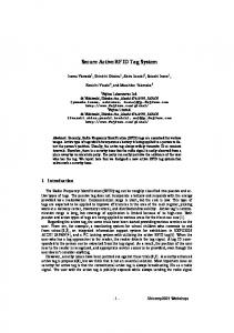
2.2. Deterministic Algorithm Deterministic algorithm, which has no starvation problem, is most suitable for passive tag applications. It is categorized into binary tree protocol and query tree protocol. Both of these protocols require all tags response at the same time and the reader identify corrupted bits [6]. In binary tree protocol, all tags have a register to save previous inquiring result. It has disadvantage of complicated tag implementation, and the tag in overlapped range of two readers will show incorrect operation. Query tree protocol does not require tag’s own counter. Instead of using counter, the reader transmit prefix and tags are response their rest bits if it matches the prefix. Query tree protocol is a memory-less protocol and tags has low functionality. However, it is slower than binary tree protocol for tag identification. Figure 3 shows the difference between binary tree algorithm and query tree algorithm. In binary protocol [5], a reader broadcast 0 at t0, two tags whose IDs 0001 and 0011 will transmit next bit whose data are all 0 and increase their counters. Next time t1, the reader broadcast 0 (second bit data), and the two tags 0001 and 0011 also responds next bit and increase their counter. But, at this time, the reader detects collision. At t2, the reader broadcast 0 (third bit data), and only the tag with ID 0001 transmits its data and reset its counter. In query tree protocol [6], the reader requests their ID with empty prefix, and all tags can transmit their ID. As a result, received four bits are totally corrupted. Next, the reader requests with prefix 0, the tags with ID 0001 and 0011 will transmit their remaining bits [0X1]. The reader can know third bit is in collision, and it requests with prefix 000. Only one tag whose ID is 0001 will transmit fourth bit as one.
Figure 3. The difference between binary tree algorithm (a) and query tree algorithm (b)
Although the prefix increase bits between tags and reader in query tree protocol, it does not requires state memory in tags (low functionality), and can be robust to errors. In this paper, we proposed a modified query tree protocol with collision resilient symbol.
3. Multi-State Query Tree Protocol with Collision Resilient Symbols In this paper, we propose multiple state query tree protocol. It uses multiple vector symbols instead of single binary (0 or 1) symbol. We modify the bit based prefix match and bit based transmission using symbol based procedure. It has strong advantage of faster identification speed, low power consumptions and robustness under low SNR region. To solve the small number of tags and compatibility with the electronic product code, we use 32-bit ID, which composed of two 16-bit BIBD codes. Each 16-bit BIBD code is based (16, 4, 1)BIBD, and it can support 20*20 users. To increase the number of supported tags, we can use hybrid scheme, where small part uses BIBD scheme to be compatible with EPC Global Code.
3.1. Design of Multi-State Query Tree Protocol Algorithm To identify tags, we suggest multiple state query tree protocol, which is variation of query tree protocol. The query tree algorithm consists of rounds of queries and response. In each round the reader asks the tags whether and of their IDs contains a certain prefix. If more than one tag answer, then the reader knows that there are at least two tags having that prefix. The reader then appends symbol 1, 2, ⋅⋅⋅ or 20 to the prefix, and continue to query for longer prefix. When a prefix matches a tag uniquely, that tag can be identified. Therefore, by extending the prefixes until only one tag’s ID matches, the algorithm can discover all the tags.
Figure 4. the idea of multiple state query tree protocol with collision resilient symbol
The figure 4 describes our idea. When there are four tags in reader’s radio range, we can identify two tags (tag1 and tag2) at t2. Table 1 shows the example of one tag identification procedure when there are four tags as shown figure 4. Table 1. Detailed procedure of multiple state query tree protocol for one tag identification.
Time t0
Reader request Null
t1
S4
t2
S4 S18
Tag response Tag1: S4 Tag2: S4 Tag3: S6 Tag4: S8 Tag1: S18 Tag2: S18 Tag3: Tag4: Tag1: S5 Tag2: S7 Tag3: Tag4: -
Note All tags response symbols - : means response
are first
not
The tag1 and tag2 are identified
In the query tree protocol, a reader detects collision bit by bit. But in our scheme can detect collision with 16 bit vector symbols which have twenty symbols. And all tags which are matched the prefix, transmit their remained bits in query tree protocol, but in multiple states query tree protocol, they transmit their next one symbol which is 16 bits. The following describes the protocol: Algorithm: Multiple State Query Tree Protocol Set the prefix empty do { rx-signal = request (with the prefix) if (rx-signal is no response ) then if (the prefix is not empty) then delete last symbol in the prefix else terminate fi else Symbol = decode (the rx-signal) add symbol in to end of the prefix fi if (size of prefix == size of tags symbol) then ensure that existence of the tag and make it not response (mute) delete last symbol in the prefix fi od
Suppose that the RFID system use 48 bits for IDs, which consist of three symbols and supports 8000 tags. Each tag has unique path in the query tree and its depth is 3. Therefore we can identify one tag at most 3 times transmission. When a reader request next symbol with prefix, the tags transmit their next 16-bit symbols and the prefix matches with one tag’s all symbol, the tag must send conform message. For example, there 4 tags whose ID are [4 18 5], [4 18 7], [8 9 2], [6 8 3] in the reader, the reader requests command bellows: Table 2. The procedure for all tags identification using multiple state query tree algorithm, *1: one of them response, *2: one tag is identified and muted
iteration 1 2 3 3-1 4 4-1 5 6 7 8 9 9-1 10 11 12 13 14 14-1 15 16 17
Reader request Null [4] [4 18] [4 18 5] [4 18] [4 18 7] [4 18] [4] Null [8] [8 9] [8 9 2] [8 9] [8] Null [6] [6 8] [6 8 3] [6 8] [6] Null
Tags response [4] [18] [5]*1 Confirmed*2 [7] Confirmed*2 Not response Not response [8] [9] [2] Confirmed*2 Not response Not response [6] [8] [3] confirmed Not response Not response Not response
At the 3rd iteration in table 2, although there are two tags whose prefix [4, 18], the one tag whose closest from reader or strongest signal at reader will be identified with our protocol. To support 8000 tags, the other protocol needs 13 bits (8192 tags) and 13 iterations to identify one tag in worst case but our scheme needs only 3 iterations in worst case.
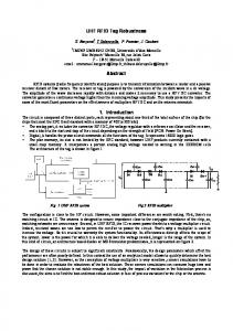
3.2. Design of Collision Resilient Symbol using Balanced Incomplete Block Design Code The definition of (v, k, λ)-BIBD code is set of kelement subsets (blocks) of v-element set χ, such that each pair of elements of χ occurs together in exactly λ
blocks. The (v, k, λ)-BIBD has total of n= λ (v2– v)/(k2-k) blocks, and we can represent (v, k, λ)-BIBD code an v*n incident matrix, where C(i,j) is set to 1 when the i-th element belongs to the j-th block and set to 0 otherwise [8]. Suppose that the symbols are derived from (v, k, 1)BIBD, all possible symbols are n=(v2-v)/(k2-k) and it is one out of frame-proof codes. With the frame-proof code, not collapsed bits gives clue for mixed symbols, and when less the k symbols are collapsed, at least one bits remains. [9] Figure 5 shows the example of (7, 3, 1)-BIBD which can identify up to 3 symbols at one transmission. For example, when the 1-st, 2-nd and 3th symbols (column) collide, the first bit remains one. On the contrary, if one bit is set to one and the others are collapsed, the reader knows that what three symbols really sent. If one or more bits are not corrupted, we can make partition into two disjoint subsets and the one has less than 3 tags and it has unique elements. e.g) when third bit is 1, the subset has first, sixth and seventh symbols. As shown in Figure 5, (7, 3, 1)-code can represent only 7 symbols and identify up to 3 symbols within one transmission, we can redesign the parameter (v, k). (16, 4, 1)-BIBD can support n = (16*15)/4*3=20 symbols.
Figure 5. Geometric (a) incident matrix (b) representation of (7, 3, 1)-BIBD
Although it lacks supported tags, it has strong advantage in identification speed, low power consumptions and robustness under low SNR region. To solve the small number of tags and compatibility with the electronic product code, we can compose of multiple BIBD codes. For instance, 32bits are divide into two 16 bits, and two 16 bits are (16, 4, 1)-BIBD codes, to support 20*20 users, or adopt hybrid scheme where small part uses BIBD scheme for compatible EPC Global Code.
4. Experimental Results In our experimentation, we assume AWGN (additive white Gaussian noise) model without fading
10
no-collsion 2 symbols 3 symbols 4 symbols
-1
Symbol Error Rate
10
x 10
4
10 8 6 4 2 0 0
SNR= SNR= SNR= SNR= 50 100 the number of tags (collisions)
-5 dB 0 dB 5 dB 10 dB 150
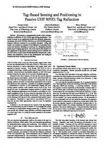
Figure 7. The tag identification performance using 6 symbols (16*6=96bits) for one tag and it can support 20^6 users
5. Conclusions In this paper, we proposed a collision detection and recovery algorithm for RFID tag collision cases. We designed the basic code using (v, k, λ) BIBD (balanced incomplete block design) code, and it can identify symbols when up to k symbols are collapsed. Our scheme does not require re-transmission, which costs power consumption. We simulated our scheme over various radio environments using AWGN channel model. Our scheme shows good collision detection and ID recovery (average k symbols for bad radio environments).
SYMBOL ERROR RATE(MAX)
0
12 The average bits to identify all tags
for radio channel, and used (16, 4, 1) BIBD code to identify maximum 20 symbols (i.e. 20 = 16*(161)/(4*(4-1))) for collision case. We repeat 10,000 times randomly select symbols and collides. We assume that when reader transmits RF with power 1, tags will share fairly 1/k. Figure 6 shows the symbol error rate over various RF channel environments (signal to noise ratio between tags and reader). Our scheme shows better ID identification over increased SNR, and it gets worse as the number of symbols in a RF reader zone and SNR decreases. Simulation results show that we can achieve successful identification for maximum 4 symbols using (16, 4, 1) BIBD code. Mathematically, (16, 4, 1)-BIBD can 4 symbols at once, interference and fading degrade performance when 4 symbols. Depending on the RF environments, we can choose the parameter (v, k, λ) for better coverage and symbol identification performance.
-2
10
-3
10
References -4
10
-5
0
5 Signal to Noise Ratio (dB)
10
15
Figure 6. Symbol Error Rate using (16, 4, 1)-BIBD Figure 7 shows that our scheme has no degradation of performance when the power of signal is bigger then noise and operates well even extremely low signal to noise ratio (SNR). It support 6.4*10^7 tags. When 100 tags are one reader range under low SNR (-5dB), our scheme needs 6*10^4 bits between reader and tags to identify all tags. According to protocol for 900Mhz class 0 RFID [5], the transmission time between reader and tag is 12.5 microsecond, Our scheme can identify 100 tags within 0.75 (6*10^4*12.5*10^-6) second. Although it wastes bits, the identification speed is very fast. It can be adopted small/medium domain real time tracking system.
[1] K Finkenzeller, “RFID Handbook, Fundamentals and Application in Contact-less Smart Card and Identification,” 2nd edition, John Wiley & Sons Ltd, 2003, pp. 195-219. [2] “ISO/IEC 18000 Part 3- Parameters for Air Interface Communications at 13.56MHz”, RFID Air Interface Standards. [3] J. Cha, and J. Kim “Novel Anti-collision Algorithm for Fast Object Identification in RFID System”, IEEE ICPADS 2005, pp. 63-67. [4] H. Vogt, “Multiple object identification with passive RFID tags” IEEE Int. Conf. on System, Man and Cybernetics, vol. 3 Oct. 2002, pp. 6-9. [5] MIT Auto-ID Center, “Draft protocol specification for a 900MHz Class 0 Radio Frequency Identification Tag”, http://www. epcglobalinc.org/, Feb., 2003. [6] J. Myung and W. Lee “An Adaptive Memoryless Tag Anti-Collision Protocol for RFID Netwroks” IEEE INFOCOM 2005.
[7] F.Zhou, C. Chen, D. Jin, C. Huang, and H. Min, “Evaluation and Optimizing Power Consumption of AntiCollision Protocols for Applications in RFID System”, ACM ISLPED.04, 2004, pp. 357-362. [8] C. J. Colbourn and J. H. Dinitz, “The CRC Handbook of Combinatorial Design”, Boca Raton, FL: CRC Press, 1996. [9] D.R. Stinson. T. V. Trung, and R. Wei, “Secure Frameproof Code, Key Distribution Patterns, Group Testing Algorithm and Related Structures”, J. Statist. Planning Inference, vol. 86, 2000, pp. 595-671