(FFT)-accelerated approach designed to handle many of the dif- ... einfodaily.com). J. Orchard is with the David R. Cheriton School of Computer Science,. University of ..... The cost function in (7) has four degrees of freedom (two translations ...
IEEE TRANSACTIONS ON GEOSCIENCE AND REMOTE SENSING, VOL. 46, NO. 11, NOVEMBER 2008
3917
Efficient FFT-Accelerated Approach to Invariant Optical–LIDAR Registration Alexander Wong, Student Member, IEEE, and Jeff Orchard, Member, IEEE
Abstract—This paper presents a fast Fourier transform (FFT)-accelerated approach designed to handle many of the difficulties associated with the registration of optical and light detection and ranging (LIDAR) images. The proposed algorithm utilizes an exhaustive region correspondence search technique to determine the correspondence between regions of interest from the optical image with the LIDAR image over all translations for various rotations. The computational cost associated with exhaustive search is greatly reduced by exploiting the FFT. The substantial differences in intensity mappings between optical and LIDAR images are addressed through local feature mapping transformation optimization. Geometric distortions in the underlying images are dealt with through a geometric transformation estimation process that handles various transformations such as translation, rotation, scaling, shear, and perspective transformations. To account for mismatches caused by factors such as severe contrast differences, the proposed algorithm attempts to prune such outliers using the random sample consensus technique to improve registration accuracy. The proposed algorithm has been tested using various optical and LIDAR images and evaluated based on its registration accuracy. The results indicate that the proposed algorithm is suitable for the multimodal invariant registration of optical and LIDAR images. Index Terms—Fast Fourier transform (FFT), image registration, intersensor, light detection and ranging (LIDAR), optical, remote sensing, sum of squared differences (SSD).
I. I NTRODUCTION
I
MAGE registration refers to techniques used to bring images taken at different perspectives, times, and/or sensor technologies into alignment with each other. Such techniques are important in the field of remote sensing for tasks such as map rectification and change analysis. Conventional registration techniques used in remote sensing tools require that the user manually select a set of control points (CPs) on the remote sensing images under evaluation. The selected CPs are subsequently used to perform transform estimation to determine the geometric transformation needed to bring the images into alignment. Given the laborious nature of manually selecting CPs for individual remote sensing images, image registration techniques that automate the process of aligning remote sensing images are desired.
Manuscript received May 7, 2007; revised December 18, 2007. Current version published October 30, 2008. This work was supported by the Natural Sciences and Engineering Research Council of Canada. A. Wong is with the Department of Systems Design Engineering, University of Waterloo, Waterloo, ON N2L 3G1, Canada (e-mail: alexanderwong@ einfodaily.com). J. Orchard is with the David R. Cheriton School of Computer Science, University of Waterloo, Waterloo, ON N2L 3G1, Canada. Digital Object Identifier 10.1109/TGRS.2008.2001685
A particularly difficult scenario for multimodal registration of remote sensing images is the registration of light detection and ranging (LIDAR) and passive optical images. Passive optical images refer to remote sensing images that are acquired in the visible and near-infrared spectral bands using passive sensing systems. Optical images may be panchromatic (e.g., IKONOS PAN) or multispectral (e.g., LANDSAT MSS, and IKONOS MS). The focus of this research is on panchromatic images. As such, it should be noted that panchromatic passive optical images will be simply referred to as optical images in the rest of the paper. LIDAR, on the other hand, constructs an image in an active manner. In a LIDAR system, electromagnetic pulses in the infrared, visible, or ultraviolet ranges are emitted from a transmitter. The time delay between the transmission of the signal and the detection of the reflected signal at the receiver is then measured to determine the altitude to an object or surface. LIDAR systems hold a number of advantages over radio detection and ranging (RADAR) systems. First, LIDAR uses much shorter wavelengths than RADAR and so can image features that are smaller than that possible with RADAR. Furthermore, LIDAR radiation is generally not modulated and thus possesses high phase coherency. As such, LIDAR systems can provide imaging of objects and surfaces at a very high resolution compared to RADAR systems. One very useful application for LIDAR is to measure the range of distant objects and surfaces. The focus of this research is on aerial LIDAR elevation maps. Practical applications for aligned LIDAR and optical images include building detection and reconstruction [2]–[4] and canopy modeling [5]. A number of important issues make LIDAR–optical image registration a particularly difficult task. 1) Symmetric CP detection: In traditional registration techniques as well as newer automatic local-similarity-based techniques, a set of symmetric CPs must be selected or detected in both images for an image pair for the registration to function. This is often found by finding points of interest within each image and then matching them using a similarity metric. However, given the substantially different characteristics captured by LIDAR and optical sensing technologies, it is very difficult to find the same points of interest within each image. 2) Intensity mapping: To visualize the remote sensing data acquired by a sensor, the data are remapped such that an image representation of the data can be constructed. Due to the substantial differences in LIDAR and optical remote sensing techniques, the data acquired from these modalities have very different intensity mappings. This makes it very difficult to perform direct similarity comparisons between LIDAR and optical images as they
0196-2892/$25.00 © 2008 IEEE
Authorized licensed use limited to: IEEE Xplore. Downloaded on April 8, 2009 at 11:25 from IEEE Xplore. Restrictions apply.
3918
IEEE TRANSACTIONS ON GEOSCIENCE AND REMOTE SENSING, VOL. 46, NO. 11, NOVEMBER 2008
have very different intensity mappings. It is important to note that the intensity channel information of LIDAR systems, if available, can be used to improve registration accuracy as the contrast differences between that data and optical data would be noticeably reduced. However, since that information may not be available in different situations, a method that can handle more difficult scenarios in the absence of this information is desired. 3) Structural characteristics: As with intensity mapping, the substantial differences in LIDAR and optical remote sensing techniques means that the structural characteristics acquired by optical imaging may not be present in the LIDAR image. This makes it difficult to perform similarity comparisons between LIDAR and optical images based solely on structural characteristics such as edges and shape. The proposed algorithm aims to address all of the above issues. The main contribution of this paper is an efficient nonrigid automatic registration system designed for registering optical and LIDAR images. The algorithm addresses the difficulties associated with the registration of optical and LIDAR images. The proposed algorithm utilizes an exhaustive region correspondence search process to find the globally optimal correspondence between regions from the optical image and the LIDAR image, searching over all translations for various rotations. This alleviates the problem of finding symmetric CPs in both images. The cost of an exhaustive search is substantially reduced by exploiting the fast Fourier transform (FFT) [1]. The differences in intensity mapping between optical and LIDAR images are addressed through an integrated local intensity mapping transformation optimization process. Finally, 4the random sample consensus (RANSAC) is used to prune incorrect CP pairs to improve registration robustness. In this paper, previous work in automatic image registration is presented in Section II. The underlying theory behind the proposed algorithm is discussed in Section III. An outline of the proposed algorithm is presented in Section IV. The methods and data used to test the effectiveness of the algorithm are outlined in Section V. The registration accuracy of the algorithm is presented and discussed in Section VI. Finally, conclusions are drawn based on the results in Section VII.
3) Low-level feature-based techniques [17]–[22]: Such low-level feature-based techniques use the similarity between low-level features such as edges and corners extracted from the images to determine the alignment between the images. These feature-based techniques are most useful in situations where distinctive structural details are present within both of the images. 4) High-level feature-based techniques [23], [24]: Highlevel feature-based techniques use the similarity between high-level features such as regions, buildings, and roads extracted from the images to determine the alignment between the images. High-level feature-based techniques are most useful in situations where distinctive but wellknown shapes can be found within both of the images, as such high-level features are usually evaluated based on metrics such as area. To the best of our knowledge, there has been no successful technique for performing automatic nonrigid registration of optical and LIDAR images in an efficient and robust manner. Furthermore, testing shows that current registration techniques are not suited for this particular application. The main issue with previous registration techniques, including those related to remote sensing images, is that they do not take into account the nature of optical and LIDAR images. A large number of registration schemes perform similarity comparisons on pixel intensities in a direct manner. However, given the differences in intensity mappings between LIDAR and optical images, finding matches using these techniques is not possible as the intensity mappings would differ greatly between the two images. Other techniques designed for multimodal registration tried to address this issue by using structure-based feature spaces such as edges. However, LIDAR and optical images often capture different structural characteristics that makes these techniques ineffective for this situation, particularly local similarity-based techniques that require matching points of interest to be detected in both the LIDAR and optical images. This issue will be illustrated in the experimental results when a structure-based method is used. The goal of this paper is to address each of the aforementioned issues to develop an algorithm that performs nonrigid optical–LIDAR registration in an efficient and robust manner.
II. B ACKGROUND
III. T HEORY
Research in automated image registration has resulted in a variety of useful techniques. These techniques can be categorized as follows. 1) Intensity-based techniques [6]–[13]: Intensity-based techniques use the similarity between pixel intensities to assess the alignment between two images. Similarity evaluation techniques used in these techniques include mutual information [6] and maximum likelihood [9]. 2) Frequency-based techniques [14]–[16]: Frequencybased techniques use characteristics such as phase to determine the alignment between two images. A popular frequency-based technique is phase correlation, which has been extended to handle geometric distortions such as rotation and scaling [15].
The proposed algorithm is a multistage algorithm that utilizes various concepts to address the issues that arise when registering optical images with LIDAR images. It is important to explain the underlying theory behind these concepts to understand how they can be used to address the issues outlined in Section I. The following sections outline the proposed approaches to conquer each of the issues mentioned above: CP detection, efficient region correspondence, feature mapping incongruency, and robust geometric transform determination. The optical and LIDAR images are assumed to be at the same spatial resolution. If the optical image and the LIDAR image are at different spatial resolutions, then the images are resampled such that they are at the same scale as each other. For testing purposes, the image with the finer resolution is downsampled to that of
Authorized licensed use limited to: IEEE Xplore. Downloaded on April 8, 2009 at 11:25 from IEEE Xplore. Restrictions apply.
WONG AND ORCHARD: EFFICIENT FFT-ACCELERATED APPROACH TO INVARIANT OPTICAL–LIDAR REGISTRATION
3919
the coarser resolution to reduce computational cost. This is sufficient in most cases, particularly since CPs are determined with subpixel accuracies. A. CP Candidate Detection In many nonrigid image registration algorithms, it is necessary to first determine an initial set of CP candidates from both of the images under evaluation. In automatic image registration, initial CP selection is commonly performed using feature detectors that attempt to determine significant points of interest within the images [25]–[28]. Although this has been shown to be effective in a number of intrasensor and intersensor scenarios, the same cannot be said for optical and LIDAR image pairs. Due to the way LIDAR and optical remote sensing techniques capture information, it is often the case that structural characteristics captured using optical sensing techniques are not present in the LIDAR image. Therefore, the use of feature detectors to find symmetric points of interest in both the optical and LIDAR images is very difficult. One simple approach to addressing this issue would be to simply assign CPs to images at fixed intervals. However, this approach does not account for the fact that certain regions within an image may contain little information for the purpose of similarity matching. As such, this may result in a large number of false matches between empty regions. The proposed algorithm takes a different approach to the aforementioned problem. Instead of extracting points of interest from both images in the hopes of matching corresponding points, the proposed algorithm extracts points of interest from only one of the two images. For each point of interest, the other image is exhaustively searched to find its best-matching location. This approach alleviates the need to find symmetric points of interest in both the LIDAR and optical images. In the proposed algorithm, local normalization is performed on the optical image to compensate for nonuniformity in image illumination and contrast f (x, y) − μl (x, y) f¯(x, y) = σl (x, y)
(1)
where μl and σl are the local mean and local standard deviation, respectively. One of the caveats with performing local normalization on an image is that it may amplify the presence of noise, leading to false points of interest. Luckily, the effect such false points of interest may have on registration accuracy in the proposed algorithm is small for several reasons. First, unlike many local similarity-based registration algorithms, the proposed algorithm utilizes an exhaustive region correspondence search strategy that does not require that matching points of interest exist in both images. Hence, a false point of interest in the optical image due to noise would still yield a globally optimal region correspondence in the LIDAR image over all translations for various rotations, therefore substantially reducing the effect of noise on registration accuracy. Furthermore, the proposed algorithm performs outlier rejection to prune outlier CP candidate pairs. Therefore, if a false point of interest does in fact lead to a false CP pair, there is a high likelihood that it will be removed from the final set of CP pairs. After the local
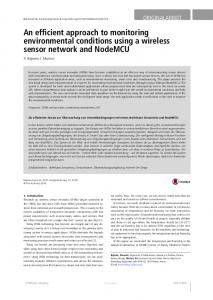
Fig. 1. Extracted CP candidates (as indicated by crosses).
normalization, the modified Harris corner detector presented in [28] is performed. Finally, only the strongest n points of interest are used as CP candidates, where n is the number of points of interest desired. The strength of a point of interest is determined based on the Harris corner strength. The choice of n is also an important factor to consider and is a tradeoff between computational cost and the robustness of the algorithm. Although the appropriate choice of n can vary depending on the underlying image characteristics, the use of 100 points of interest has been found to be typically sufficient for many situations. Once the points of interest have been selected, the position of each point is readjusted for subpixel accuracy by fitting a 2-D quadratic to the corner strength in its local neighborhood and then finding the maximum of the quadratic. An example of extracted CP candidates from an optical image is shown in Fig. 1. B. Exhaustive Region Correspondence Search After CP candidates have been determined in the optical image, a set of regions of interest is extracted from the optical image based on the location of the CP candidates. In the proposed algorithm, a circular region of neighboring pixels is extracted around each CP candidate point (acting as the center point of the region) in the optical image as a region of interest. The radius of the region of interest is important and needs to be chosen based on the image resolution and underlying image characteristics. Once the regions of interest have been determined, an exhaustive region correspondence search is performed between the LIDAR image and each region of interest. This approach is very different than conventional approaches that attempt to perform region correspondence at fixed points of interest. There are a number of advantages to this approach. First, unlike techniques that attempt to match
Authorized licensed use limited to: IEEE Xplore. Downloaded on April 8, 2009 at 11:25 from IEEE Xplore. Restrictions apply.
3920
IEEE TRANSACTIONS ON GEOSCIENCE AND REMOTE SENSING, VOL. 46, NO. 11, NOVEMBER 2008
discrete points of interest from an image pair, an exhaustive search ensures that a globally optimal match is found over all translations for various rotations between each region and the corresponding LIDAR image. Second, as stated earlier, this search strategy does not require symmetric points of interest to be detected in both the optical and LIDAR images. Since multiple regions of interest are evaluated, the proposed algorithm is also more robust than many of the existing global registration techniques because the final transformation model between the optical and LIDAR images is determined based on the collective consensus of CP pairs. It is important to point out that the correspondence between small regions of interest can be sufficiently modeled based on translation and rotation. However, the final global transformation between the optical and LIDAR images is estimated based on a more complex model such as a perspective model or high-order polynomial model. The proposed algorithm utilizes the sum of squared differences (SSD) cost metric to determine the optimal correspondence between a region of interest and the LIDAR image. Therefore, it is important to discuss how the region correspondence can be evaluated using the SSD cost function. Given a LIDAR image f and an optical image g, the similarity between the two images within a region of interest in the optical image can be determined using the cost function C as expressed by � (f (x) − g(x))2 R(x) (2) C= x
where x is the coordinate of an image pixel, and R(x) is the masking function over g(x), where R(x) = 1 within the region of interest and R(x) = 0 otherwise. Based on this cost function, the similarity between a region of interest from g and an arbitrary region in f can be viewed as the similarity between image g and image f translated by vector v. Therefore, the cost function in this case can be expressed as � (f (x − v) − g(x))2 Ri (x) (3) Ci (v) = x
where Ci (v) is the cost function between image g and image f shifted by vector v over a region of interest i. The cost function Ci (v) is minimized to achieve the best spatial correspondence between f and g. Hence, vi is determined such that � � � 2 (f (x − v) − g(x)) Ri (x) . (4) vi = arg min v
x
The resultant optimal translation vi can be seen as a translation vector that aligns image f with image g given the region of interest i. As such, the centroid of the region in image f that corresponds to the region of interest i in image g can be computed as xf,i = xg,i − vi
(5)
where xg,i is the centroid of the region of interest i in image g, and xf,i is the centroid of the corresponding region in image f . These two centroids can then be used as a CP candidate
pair. For example, suppose there exists a region of interest i centered around a point of interest at (xg , yg ) = (100, 100). After performing the exhaustive region correspondence search, it was determined that the lowest cost is found when vi = (40, 40). Therefore, the centroid of the region in the LIDAR image that corresponds to region of interest i can be computed as (xf , yf ) = (xg − 40, yg − 40) = (60, 60). In the case where georeferencing information is known, the computational performance of such an exhaustive search process can be improved by narrowing the search space in image f based on the georeferencing data. It is important to note that the SSD cost metric is highly sensitive to outliers and non-Gaussian behavior. As such, this can lead to mismatches in situations where the underlying image characteristics exhibit highly varying illumination and contrast conditions. This issue is partially compensated for in the outlier rejection process, where mismatches caused by these characteristics are pruned from the set of matched CP pairs to eliminate its effect on overall registration accuracy. C. Local Intensity Mapping Transformation Optimization One of the major issues with using the above exhaustive region correspondence technique directly between optical and LIDAR images is the fact that the intensity mappings of the images are substantially different. This renders a direct region correspondence ineffective in this situation as corresponding regions in the LIDAR image and the optical image are not represented using the same feature mapping. A common approach used in various multimodal image registration schemes is to perform similarity comparisons using structural features such as edges. However, due the substantial differences in the way LIDAR and optical imaging techniques acquire information, the structural characteristics acquired by optical imaging may not be present in the LIDAR image. Therefore, an approach based solely on structural features would result in frequent incorrect region correspondences. The proposed algorithm utilizes a different approach to addressing this problem by determining an intensity mapping transformation that transforms the intensity mapping of the optical image into those of the LIDAR image. A major point of concern to this approach is the fact that the differences in intensity mapping between optical and LIDAR are so substantial that a nonlinear transformation model would be required to obtain a global intensity mapping transformation that transforms the intensity mapping of the optical image to that of the LIDAR image. Determining such a global intensity mapping transformation would be very difficult and computationally inefficient. A more efficient and effective approach is to determine a different local feature mapping transformation for each region of interest. A substantially simpler model can be used to approximate the local intensity mapping transformation when compared to that required for a global intensity mapping transformation. The proposed algorithm uses a linear model to approximate the local feature mapping transformation that maps a region of interest i from the optical image g to that of the LIDAR image f . Given the small region of interest around each CP candidate, a linear model is typically sufficient based on the assumption
Authorized licensed use limited to: IEEE Xplore. Downloaded on April 8, 2009 at 11:25 from IEEE Xplore. Restrictions apply.
WONG AND ORCHARD: EFFICIENT FFT-ACCELERATED APPROACH TO INVARIANT OPTICAL–LIDAR REGISTRATION
that a small neighborhood of pixels should exhibit near-uniform properties. Integrating the linear feature mapping transform model into the existing cost function, f (x) is replaced by af (x) + b. The new cost function is expressed as � (af (x − v) + b − g(x))2 Ri (x). (6) Ci (v, a, b) = x
Given the above cost function, the globally optimal translation v and the optimal linear transformation parameters a and b for a particular region of interest i can be found by minimizing the cost function such that � � � 2 (af (x − v) + b − g(x)) Ri (x) . (vi , ai , bi ) = arg min v,a,b
x
(7) D. FFT Acceleration The cost function in (7) has four degrees of freedom (two translations and two coefficients). If one uses a direct approach to evaluate the cost function, it is extremely computationally expensive to exhaustively evaluate the cost function for all candidate parameter values in the 4-D parameter space. This is particularly problematic in the context of the proposed algorithm, as a set of regions of interest need to be evaluated for optimal region correspondence. An effective approach to substantially reduce the computational cost of the exhaustive region correspondence search is to reformulate the underlying cost optimization problem into a problem that can be evaluated using the FFT. This concept has been used in various research that utilize correlation-based cost functions [7], [11], [12]. First, the cost function presented in (6) is expanded as � f 2 (x − v)Ri (x) Ci (v, a, b) = a2 x
− 2a
�
+ 2ab + +
� x �
f (x − v)Ri (x)
x 2
b Ri (x) − 2b
�
g(x)Ri (x)
x
g 2 (x)Ri (x).
where f¯ = f (−x), F and F −1 represent the forward and inverse FFTs, respectively, and K represents the last three terms of the expanded form in (8). This approach to cost function evaluation has been shown to yield performance improvements over direct evaluation [11]. For the case where the LIDAR image is N × N in size and the size of the regions of interest is M × M , the computational complexity of direct evaluation is O(N 2 M 2 ), while the computational complexity of the proposed approach is O(N 2 log N ). Since log N � M 2 in practical situations, substantial performance improvements can be achieved. For example, the computational cost of processing a 1024 × 1024 image with regions of interest of size 25 × 25 using the FFT approach is roughly the same as the computational cost of processing the same image with regions of size 9 × 9 using the direct approach. Since a typical situation involves LIDAR images 1024 × 1024 in size and regions of interest 25 × 25 in size, the performance improvement achieved over the direct approach is substantial, exceeding a factor of five. Once the summations in the expanded equation have been computed for all values of v, the optimal values of a and b can then be determined for each value of v by solving a simple 2 × 2 linear system of equations [11]. Degenerative cases may occur due to the optimal values of a and b that can lead to mismatches. However, the Harris corner detector is designed to choose CPs that are distinctive, thereby substantially reducing the number of such mismatches. For the mismatches that do occur, the outlier rejection process attempts to compensate for this issue by classifying these mismatches as outliers and pruning them from the set of CP pairs. E. Rotation The methodology outlined above computes the optimal translation but does not consider rotations. However, evaluating the optimal translation and linear intensity remapping coefficients is fast enough that it is feasible to do so for a sampling of candidate rotations. We compute the optimal region correspondence over a set of discrete rotations at fixed intervals such that
f (x − v)g(x)Ri (x)
x �
3921
(8)
x
The last three terms of the expanded equation are independent of v and can be efficiently computed in a direct manner. The first three terms can be reformulated as convolutions. Although convolutions are computationally expensive when performed in a direct manner, they can be efficiently computed in the frequency domain since convolutions in the spatial domain become multiplications in the frequency domain. Therefore, the first three terms can be computed for all values of v by applying the FFT on the convolutions so that they can be evaluated as multiplications in the frequency domain. The final cost function can be expressed as � � Ci (v, a, b) = a2 F −1 F (f¯2 )F (Ri ) (v) � � − 2aF −1 F (f¯)F (gRi ) (v) � � + 2abF −1 F (f¯)F (Ri ) (v) + K (9)
vi = arg min(Ci,θ )
(10)
v
where Ci,θ is the cost for region of interest i of the image g rotated by angle θ. The increase in computational complexity is reasonable given the significant complexity reduction of the exhaustive region correspondence search gained from using the FFT. Furthermore, the added computational costs are far outweighed by the increase in robustness to local geometric distortions. F. Outlier Rejection and Geometric Transformation Estimation After a set of CP candidate pairs have been determined, the RANSAC algorithm [29] is applied to the set of CP candidate pairs to prune potential outliers. RANSAC has proven to be popular for outlier rejection due to its effectiveness and efficiency. Performing outlier rejection is very important
Authorized licensed use limited to: IEEE Xplore. Downloaded on April 8, 2009 at 11:25 from IEEE Xplore. Restrictions apply.
3922
IEEE TRANSACTIONS ON GEOSCIENCE AND REMOTE SENSING, VOL. 46, NO. 11, NOVEMBER 2008
V. T ESTING M ETHODS
Fig. 2. Final set of candidate CPs (as indicated by crosses). (Left) Optical image. (Right) LIDAR image.
because common least squares estimation methods such as the normalized direct linear transformation (DLT) algorithm [30] are highly sensitive to the presence of outliers. An example of the final set of CPs from the optical and LIDAR images is shown in Fig. 2. Using the outlier-free set of CP pairs, the nonrigid transformation that maps the LIDAR image to the optical image can be estimated using an estimation technique such as DLT. The actual geometric transformation model used for transformation estimation will depend on the geometric distortions exhibited within the optical and LIDAR images being used. For testing purposes, the proposed algorithm makes use of a projective transformation model that is capable of handling most common geometric distortions such as affine transformations (translation, rotation, scaling, and shear) as well as perspective transformations. Since any geometric transformation model may be used in the proposed algorithm, high-order polynomial transformation models may be used for situations where the LIDAR and/or optical image exhibit(s) more complex geometric distortions.
IV. R EGISTRATION A LGORITHM Based on the above theory, the proposed registration algorithm is summarized as follows, for a LIDAR image f and an optical image g. 1) Detect a set of CP candidates from f using the algorithm described in Section III-A. 2) Determine a set of CP candidate pairs between f and g by performing the region correspondence technique with the local feature mapping transform optimization and FFT acceleration described in Section III-C. Georeferencing data, if available, may be used to improve performance and accuracy of the algorithm. 3) Use the RANSAC algorithm on the set of CP candidates to prune outliers from the set of CP candidate pairs. 4) Use a model estimation algorithm to estimate a transformation using the final set of CPs. 5) Use the transformation to transform g into an aligned image g � .
The proposed algorithm was implemented in MATLAB and was tested using a set of images from Intermap Technologies Inc. and the U.S. Geological Survey (USGS). Each test set consists of a LIDAR image and an optical image that have been scaled to 8 bits per pixel. A description of each test case is described below. 1) TEST1: A pair composed of a LIDAR image and an orthorectified air photo of Highlands Ranch, CO, NW quad, at 1-m resolution. This test set was provided by Intermap Technologies Inc. 2) TEST2: A pair composed of a LIDAR image and an orthorectified air photo of Highlands Ranch, CO, NE quad, at 1-m resolution. This test set was provided by Intermap Technologies Inc. 3) TEST3: A pair composed of a LIDAR image and an orthorectified air photo of a section from New Orleans, LA, latitude/longitude: 29.0◦ 59� / − 90◦ 01� . This test set was provided by USGS. 4) TEST4: A pair composed of a LIDAR image and an orthorectified air-photo of a section from New Orleans, LA, latitude/longitude: 29.0◦ 57� / − 90◦ 02� . This test set was provided by USGS. Each LIDAR image in a test case is registered with the optical image in the same test case. For all test cases, the number of initial CP candidates was set to a maximum of 100 candidates in the optical image and the range of candidate rotations is set to ±{0◦ , 2.5◦ , 5◦ }. To demonstrate the effectiveness of the proposed algorithm when no additional information is available, each image pair is registered without the aid of georeferencing data. Aside from the primary goal of registering optical–LIDAR image pairs, it would be of interest to briefly investigate the effectiveness of the proposed method for registering other types of intersensor image data. As such, the following test case from the USGS Global Visualization Viewer project was also evaluated (using the same parameters as the optical–LIDAR test cases): • TEST5: Set of two 761 × 748 images from the USGS project, latitude/longitude: 46.0◦ / − 83.8◦ , at 240-m resolution. In image 1, sensor: Landsat 7 ETM+, band: 3, and date: 2003/4/12. In image 2, sensor: Landsat 4–5 TM, band: 5, and date: 2006/06/15. To establish a “gold standard” for comparison purposes, a set of 20 CP pairs with good spatial distribution was manually selected for each test case. To act as a reference comparison, the CPs were used to estimate reference transformations using a polynomial fit of second order as well as a perspective transformation model. Furthermore, a registration method based on maximization of mutual information as well as the low-level structure-based registration method proposed in [22] was also implemented and used for comparison. The normalized measure of mutual information used in the optimization process is that proposed by Studholme et al. [31], which was found to be effective for multimodal registration purposes. To improve the results of the mutual information implementation, an initial estimate was used to improve registration conver-
Authorized licensed use limited to: IEEE Xplore. Downloaded on April 8, 2009 at 11:25 from IEEE Xplore. Restrictions apply.
WONG AND ORCHARD: EFFICIENT FFT-ACCELERATED APPROACH TO INVARIANT OPTICAL–LIDAR REGISTRATION
3923
TABLE I REGISTRATION ACCURACY
Fig. 3.
Image registration from the TEST2 test set. (Left) Optical image. (Center) LIDAR image. (Right) Aligned images.
Fig. 4.
Image registration from the TEST1 test set after rotation. (Left) Optical image. (Center) LIDAR image. (Right) Aligned images.
gence. The measure of mutual information used is the global mutual information for the entire image. For all of the tested algorithms, a perspective transformation model was used. To judge the registration accuracy of the proposed algorithm, the root-mean-square error (RMSE) is computed for the test pairs. The RMSE is computed on a pixel basis. VI. E XPERIMENTAL R ESULTS The registration accuracy results are shown in Table I. It can be seen that the proposed algorithm achieved an RMSE that
is comparable by the manual selection of CP pairs, exhibiting an RMSE of less than five pixels in all cases. It can be observed that the average RMSE realized using the proposed algorithm is noticeably lower than that achieved using the low-level structure-based method proposed in [22] for all test cases except TEST5, where it is comparable. This is largely due to the differences in structural information captured in the optical data and the LIDAR data. Furthermore, it can also be observed that the average RMSE realized using the proposed algorithm is noticeably lower than that achieved using the maximization of the mutual information method for all test
Authorized licensed use limited to: IEEE Xplore. Downloaded on April 8, 2009 at 11:25 from IEEE Xplore. Restrictions apply.
3924
IEEE TRANSACTIONS ON GEOSCIENCE AND REMOTE SENSING, VOL. 46, NO. 11, NOVEMBER 2008
Fig. 5. Image registration from the TEST3 test set. (Left) Optical image. (Center) LIDAR image. (Right) Aligned images.
Fig. 6. Image registration from the TEST5 test set. (Left) Landsat 4–5 TM image. (Center) Landsat 7 ETM+ image. (Right) Aligned images.
cases except TEST4, where it is comparable. Examples of the optical–LIDAR registration achieved is shown in Figs. 3–6. By visual inspection, the registered results are reasonably accurate. These results demonstrate the effectiveness of the proposed algorithm for registering optical–LIDAR images.
ACKNOWLEDGMENT The authors would like to thank Intermap Technologies Inc. and the U.S. Geological Survey for the test data. R EFERENCES
VII. C ONCLUSION AND F UTURE W ORK In this paper, we have introduced an efficient approach to nonrigid invariant optical–LIDAR registration. Experimental results demonstrate good intersensor registration accuracy under various difficult optical–LIDAR image pairs. It is our belief that this method can be successfully implemented for optical–LIDAR registration and rectification purposes. Future work includes investigating higher order intensity transformation models for improving multimodal image registration accuracy, as well as testing the performance of the proposed method with imagery that has not been orthorectified.
[1] J. Cooley and J. Tukey, “An algorithm for the machine calculation of complex Fourier series,” Math. Comput., vol. 19, no. 90, pp. 297–301, Apr. 1965. [2] L. Chen, T. Teo, J. Rau, J. Liu, and W. Hsu, “Building reconstruction from LIDAR data and aerial imagery,” in Proc. IEEE Int. Geosci. Remote Sens. Symp., 2005, pp. 2846–2849. [3] F. Rottensteiner and J. Jansa, “Automatic extraction of buildings from LIDAR data and aerial images,” in Proc. ISPRS, 2002, vol. 34, pp. 295– 301. Part 4. [4] G. Vosselman, “Fusion of laser scanning data, maps, and aerial photographs for building reconstruction,” in Proc. IEEE Int. Geosci. Remote Sens. Symp., 2002, vol. 1, pp. 85–88. [5] L. Chen, T. Chiang, and T. Teo, “Fusion of LIDAR data and high resolution images for forest canopy modeling,” in Proc. 26th Asian Conf. Remote Sens., 2005.
Authorized licensed use limited to: IEEE Xplore. Downloaded on April 8, 2009 at 11:25 from IEEE Xplore. Restrictions apply.
WONG AND ORCHARD: EFFICIENT FFT-ACCELERATED APPROACH TO INVARIANT OPTICAL–LIDAR REGISTRATION
[6] H. Chen, P. Varshney, and M. Arora, “Mutual information based image registration for remote sensing data,” Int. J. Remote Sens., vol. 24, no. 18, pp. 3701–3706, Sep. 2003. [7] A. Fitch, A. Kadyrov, W. Christmas, and J. Kittler, “Fast robust correlation,” IEEE Trans. Image Process., vol. 14, no. 8, pp. 1063–1073, Aug. 2005. [8] J. Kybic and M. Unser, “Fast parametric elastic image registration,” IEEE Trans. Image Process., vol. 12, no. 11, pp. 1427–1442, Nov. 2003. [9] W. Li and H. Leung, “A maximum likelihood approach for image registration using control point and intensity,” IEEE Trans. Image Process., vol. 13, no. 8, pp. 1115–1127, Aug. 2004. [10] Z. Li, Z. Bao, H. Li, and G. Liao, “Image autocoregistration and InSAR interferogram estimation using joint subspace projection,” IEEE Trans. Geosci. Remote Sens., vol. 44, no. 2, pp. 288–297, Feb. 2006. [11] J. Orchard, “Efficient global weighted least-squares translation registration in the frequency domain,” in Proc. Int. Conf. Image Anal. Recog., 2005, vol. 3656, pp. 116–124. [12] J. Orchard, “Efficient least squares multimodal registration with a globally exhaustive alignment search,” IEEE Trans. Image Process., vol. 16, no. 10, pp. 2526–2534, Oct. 2007. [13] A. Refice, F. Bovenga, and R. Nutricato, “MST-based stepwise connection strategies for multipass radar data, with application to coregistration and equalization,” IEEE Trans. Geosci. Remote Sens., vol. 44, no. 8, pp. 2029– 2040, Aug. 2006. [14] E. Castro and C. Morandi, “Registration of translated and rotated images using finite Fourier transforms,” IEEE Trans. Pattern Anal. Mach. Intell., vol. PAMI-9, no. 5, pp. 700–703, Sep. 1987. [15] B. Reddy and B. Chatterji, “An FFT-based technique for translation, rotation, and scale-invariant image registration,” IEEE Trans. Image Process., vol. 5, no. 8, pp. 1266–1271, Aug. 1996. [16] I. Zavorin and J. Le Moigne, “Use of multiresolution wavelet feature pyramids for automatic registration of multisensor imagery,” IEEE Trans. Image Process., vol. 14, no. 6, pp. 770–782, Jun. 2005. [17] F. Eugenio, F. Marques, and J. Marcello, “A contour-based approach to automatic and accurate registration of multitemporal and multisensor satellite imagery,” in Proc. IEEE Int. Geosci. Remote Sens. Symp., 2002, vol. 6, pp. 3390–3392. [18] V. Govindu and C. Shekhar, “Alignment using distributions of local geometric properties,” IEEE Trans. Pattern Anal. Mach. Intell., vol. 21, no. 10, pp. 1031–1043, Oct. 1999. [19] C. Hsu and R. Beuker, “Multiresolution feature-based image registration,” in Proc. SPIE—Visual Communications and Image Processing, 2002, vol. 4067, pp. 1490–1498. [20] H. Li, B. Manjunath, and S. Mitra, “A contour-based approach to multisensor image registration,” IEEE Trans. Image Process., vol. 4, no. 3, pp. 320–334, Mar. 1995. [21] N. Netanyahu, J. Le Moigne, and J. Masek, “Georegistration of Landsat data via robust matching of multiresolution features,” IEEE Trans. Geosci. Remote Sens., vol. 42, no. 7, pp. 1586–1600, Jul. 2004. [22] A. Wong and D. Clausi, “ARRSI: Automatic registration of remotesensing images,” IEEE Trans. Geosci. Remote Sens., vol. 45, pt. II, no. 5, pp. 1483–1493, May 2007. [23] M. Ali and D. Clausi, “Automatic registration of SAR and visible band remote sensing images,” in Proc. IEEE Int. Geosci. Remote Sens. Symp., 2002, vol. 3, pp. 1331–1333. [24] X. Dai and S. Khorram, “A feature-based image registration algorithm using improved chain-code representation combined with invariant moments,” IEEE Trans. Geosci. Remote Sens., vol. 37, pt. 2, no. 5, pp. 2351– 2362, Sep. 1999.
3925
[25] S. Smith and J. Brady, “SUSAN—A new approach to low level image processing,” Int. J. Comput. Vis., vol. 23, no. 1, pp. 45–78, May 1997. [26] C. Harris and M. Plessey, “A combined corner and edge detector,” in Proc. 4th Alvey Vis. Conf., 1988, pp. 147–151. [27] M. Trajkovic and M. Hedley, “Fast corner detection,” Image Vis. Comput., vol. 16, no. 2, pp. 75–87, Feb. 1998. [28] A. Noble, “Descriptions of image surfaces,” Ph.D. dissertation, Oxford Univ., Oxford, U.K., 1989. [29] M. Fischler and R. Bolles, “Random sample consensus: A paradigm for model fitting with applications to image analysis and automated cartography,” Commun. ACM, vol. 24, no. 6, pp. 381–395, Jun. 1981. [30] R. Hartley and A. Zisserman, Multiple View Geometry in Computer Vision. Cambridge, U.K.: Cambridge Univ. Press, 2001. [31] C. Studholme, D. Hill, and D. J. Hawkes, “An overlap invariant entropy measure of 3D medical image alignment,” Pattern Recognit., vol. 32, no. 1, pp. 71–86, Jan. 1999.
Alexander Wong (S’05) received the B.Sc. degree in computer engineering and the M.Sc. degree in electrical and computer engineering from the University of Waterloo, Waterloo, ON, Canada, in 2005 and 2007, respectively. He is currently working toward the Ph.D. degree in the Department of Systems Design Engineering, University of Waterloo. At the University of Waterloo, he is affiliated with the Vision and Image Processing Research Group. He is the author of several papers in various fields such as computer vision, graphics, image processing, and multimedia systems published in refereed journals and conference proceedings. His research interests revolve around image processing, computer vision, and pattern recognition. He has worked on projects in image registration, image denoising, image superresolution, image segmentation, biomedical tracking, and image and video coding.
Jeff Orchard (M’03) received the B.Math. degree in applied mathematics from the University of Waterloo, Waterloo, ON, Canada, in 1994, the M.Sc. degree in applied mathematics from the University of British Columbia, Vancouver, BC, Canada, in 1996, and the Ph.D. degree in computing science from Simon Fraser University, Burnaby, BC, Canada, in 2003. Since 2003, he has been an Assistant Professor with the David R. Cheriton School of Computer Science, University of Waterloo. At the University of Waterloo, he is affiliated with the Scientific Computing Research Group, the Waterloo Institute for Health Informatics Research, and the Centre for Computational Mathematics in Industry and Commerce. His research interests revolve around applying mathematics and computation to visual data. He has worked on projects in image registration, motion compensation for medical imaging, functional MRI, and medical image reconstruction.
Authorized licensed use limited to: IEEE Xplore. Downloaded on April 8, 2009 at 11:25 from IEEE Xplore. Restrictions apply.