Efficient gamut clipping for color image processing using LHS and YIQ Christopher C. Yang The Chinese University of Hong Kong Department of Systems Engineering and Engineering Management Shatin, New Territories, Hong Kong E-mail:
[email protected] S. H. Kwok The Hong Kong University of Science and Technology Department of Information and Systems Management Clear Water Bay, Kowloon, Hong Kong
Abstract. Out-of-gamut problems exist in color image processing and color reproduction in different devices. Extensive research has been done on transforming out-of-gamut colors to the inside of the output device’s color gamut for color reproduction. We focus on the out-ofgamut problem in color image processing. Luminance, hue, and saturation (LHS) and YIQ color coordinate systems are investigated. Efficient techniques for luminance and saturation processing and gamut clippings are presented. The efficient technique of luminance clipping for LHS is developed based on scaling, and the efficient technique of luminance clipping for YIQ is developed based on shifting. However, the efficient technique of saturation clipping for both LHS and YIQ is a combination of scaling and shifting. Such efficient techniques reduce the complexity of forward and backward transformations between the color representing the color coordinate system (RGB) and the processing color coordinate system (LHS or YIQ) significantly. Illustrations show the result of RGB, luminance, and saturation clippings. Saturation clipping is the best in terms of maintaining the hue and contrast of the original image. Experiments are also conducted to measure the efficiency of the proposed efficient techniques. It shows that the processing time is reduced by 27% comparing with the conventional technique using forward and backward color transformations. © 2003 Society of Photo-Optical Instrumentation Engineers. [DOI: 10.1117/1.1544479]
Subject terms: color image processing; LHS; YIQ; color gamut; gamut clipping. Paper 020037 received Feb. 4, 2002; revised manuscript received Aug. 6, 2002; accepted for publication Sep. 10, 2002.
1
Introduction
Color clipping is a technique to transform out-of-gamut colors to the color gamut being used. Out-of-gamut problems always exist in two typical situations. 1. Due to the physical limitation 共e.g., phosphors, colorants, substrates, etc.兲 of the output devices, such as cathode ray tube 共CRT兲 monitors and hardcopy color printers, color gamut differences among these devices is noticeable in our daily applications. 2. Due to the limitation of the resolution for image storage and display, such as RGB, color gamut difference between the color coordinate systems for image storage/ display and the color coordinate systems for color image processing is common. After color image processing using a color coordinate system corresponding to the perceptual attributes of the human visual system, such as LHS and YIQ, the color may not be able to map to the color gamut for image input/output (0⭐R,G,B⭐1). Much research work has been done to study the gamut of CRT monitors and hardcopy printers.1– 6 The CIELAB color space, a uniform color space, has been explored for color mapping to preserve the appearance of a color image as much as possible when the image is reproduced by CRT monitors and hardcopy printers. We focus on the out-of-gamut problem in color image processing. In color image processing, colors (0⭐R,G,B ⭐1) in an RGB color space 共a color space used to represent color images兲 are first transformed to a color space Opt. Eng. 42(3) 701–711 (March 2003)
0091-3286/2003/$15.00
corresponding to human perception, such as CIELAB, LHS, and YIQ, before the processing. After processing, some of the colors are no longer within the RGB color gamut. R, G, B⬎1 or R, G, B⬍0. Therefore, these out-ofgamut colors need to be clipped before they can be represented in an RGB color gamut again. CIELAB color space is used in gamut clipping for different color devices due to its uniformity, although there are recent reports of the substantial discrepancies between observed uniform color spaces and calculated L* a* b* . 5 In addition, the transformation between RGB and CIELAB is complicated and time consuming, which is not preferred in color image processing. LHS and YIQ color coordinate systems are utilized in this work because efficient techniques can be developed to bypass the complicated forward and backward transformations. 1.1 Color Gamut Clipping Many color gamut clippings have been investigated in the literature, especially the CRT gamut. Although we focus on color gamut clipping for image processing, existing techniques for all purposes are first reviewed. Typical color gamut clipping techniques include: • chroma clipping • centroid clipping • lightness clipping © 2003 Society of Photo-Optical Instrumentation Engineers
701
Yang and Kwok: Efficient gamut clipping . . .
• orthogonal clipping 共to the boundary of the gamut兲 • cusp clipping or chord clipping • mapping functions, e.g., sigmoid lightness mapping function and chroma mapping function • categorical mapping. Next are some recently developed clipping techniques. Ito, Katoh, and Ohno7,8 proposed to clip the out-ofgamut color to the reproduction gamut boundary. The smallest E value calculated by a weighted color difference formula CIELAB is employed. Other color difference for9 * , 9 ⌬E94 , 10 ⌬ECMC , 11 ⌬EBFD , 4 and mulas, ⌬E* ab , ⌬Euv 7 ⌬Ewt , were also studied. Braun and Fairchild investigated the hue nonuniformities in CIELAB1 and developed the sigmoidal lightness mapping functions to boost the image contrast selectively when the original gamut is mapped into the reproduced gamut.12 Shimizu et al.13 proposed the chroma proportional clipping 共CPC兲 method with the International Color Consortium 共ICC兲 color management framework. MacDonald and Morovic14 compared several methods of gamut mapping on fine art painting using La* b* color space. These methods are the paper cast removal, lightness mapping, orthogonal clipping, chord clipping, and gamut compression. For different paintings with different percentages of out-of-gamut, different gamut mapping methods are reported to have the best performance. Laihanen15 presented two approaches of color mapping using LABNU, a color space similar to CIELAB. These approaches are gamut compressing with constant hue and lightness and gamut compression toward the center of lightness axis. We develop the efficient technique of color gamut clipping for color image processing using luminance, hue, and saturation 共LHS兲 and YIQ. RGB, luminance, and saturation clippings are compared. Efficiency of the clipping techniques is also investigated. 2 Color Coordinate Systems Many three-dimensional color spaces have been proposed and adopted in different applications in the last few decades. All of them take different approaches to represent the trichromatic nature of light to satisfy their objectives. For example, the CIELAB and CIELUV spaces11 promote uniformity of practice. In CIELUV, if two colored lights, C 1 and C 2 , are mixed additively to produce a third color C 3 , C 3 lies on a straight line on a chromaticity diagram joining C 1 and C 2 at a position that can be calculated from the relative amounts of C 1 and C 2 . The LHS color space16,17 is derived based on the Maxwell triangle in the RGB color cube. The LHS color space is a cylindrical coordinate system where the vertical axis corresponds to the luminance and the horizontal plane corresponds to the chromatic perceptions. The hue, saturation, and value 共HSV兲 and hue, lightness, and saturation 共HLS兲 color spaces,18 which are also known as the hexcone model and double hexcone model, respectively, are similar to the LHS color space except that the transformations are simplified. The generalized lightness, hue, and saturation 共GLHS兲 color model,19 developed by Levkowitz and Herman, is a generalization of HSL, HSV, HLS, and other special models. 702
Optical Engineering, Vol. 42 No. 3, March 2003
Fig. 1 Maxwell triangle in the RGB cube.
The National Television Systems Committee 共NTSC兲 develops the YIQ color space for commercial color television broadcasting and other applications. YIQ is a recording of RGB for transmission efficiency. LHS and YIQ are utilized here due to their efficiency of transformation. 2.1 LHS Color Coordinate System The LHS color coordinate system has three components, luminance 共L兲, hue 共H兲, and saturation 共S兲. Its development is based on the Maxwell triangle in the RGB color cube as shown in Fig. 1. The corners of the Maxwell triangle are 关1,0,0兴, 关0,1,0兴, and 关0,0,1兴 in the RGB cube. Given a vector in the RGB cube, the length of the vector OP is proportional to the luminance, and the intersection of the vector OP and the Maxwell triangle represent the attributes of hue and saturation. Given the intersection point P⬘ on the Maxwell triangle in Fig. 2, the hue is the angle between the CP⬘ and CR, and the saturation is the ratio of the length CP⬘ to the length CQ, where C is the center of the Maxwell triangle. 2.1.1 Transformation from RGB to LHS The transformation from the RGB color coordinate system to the LHS color coordinate system17,20 is as follows:
Fig. 2 The intersection point OP⬘ in the Maxwell triangle.
Yang and Kwok: Efficient gamut clipping . . .
L⫽0.299R⫹0.587G⫹0.114B,
共1兲
N H⫽ ⫹cos⫺1 , 兵 6 关共 r⫺1/3兲 2 ⫹ 共 g⫺1/3兲 2 ⫹ 共 b⫺1/3兲 2 兴 其 1/2 共2兲 where r⫽
G B R , g⫽ , b⫽ R⫹G⫹B R⫹G⫹B R⫹G⫹B
再 再
0 deg
The backward transformation from the LHS color coordinate system to the RGB color coordinate system has not been reported in any literature so far, and it can be derived geometrically in a straightforward manner as shown in the Appendix in Sec. 9. The transformation of LHS to RGB is different from the transformation from GLSH to RGB, since the forward transformation is not based on the approximation. The formulation is shown as follows: R⫽R *
L , L*
共4兲
L , L*
共5兲
L , L*
共6兲
if r⫽min共 r,g,b 兲 G⫽G *
⫽ 120 deg if g⫽min共 r,g,b 兲 240 deg if b⫽min共 r,g,b 兲
N⫽
2.1.2 Transformation from LHS to RGB
B⫽B *
2r⫺g⫺b
if r⫽min共 r,g,b 兲
2g⫺r⫺b
if g⫽min共 r,g,b 兲
where
2b⫺r⫺g
if b⫽min共 r,g,b 兲
L * ⫽0.299R * ⫹0.587G * ⫹0.114B *
S⫽1⫺3
min共 R,G,B 兲 . R⫹G⫹B
共3兲
LHS versus GLHS. The GLHS color model is a generalization of three special models, HSL, HSV, and HLS, where the lightness is the weighted sum of the maximum, medium, and minimum values of R, G, and B with different sets of weights. That means l(c)⫽w min min(c) ⫹wmidmid(c)⫹w max max(c), where w min⫽wmid⫽w max ⫽1/3 for HSL; w max⫽1 and w min⫽wmid⫽0 for HSV; w min ⫽wmax⫽1/2 and w mid⫽0 for HLS. In LHS, L is the luminance of a color based on the brightness of R, G, and B perceived by humans but it is not a weighted sum of the maximum, medium, and minimum of R, G, and B values. L is the same as the luminance in YIQ, Y, and it is the same as the Y component in the computation of L * in CIELAB and CIELUV. The hue used in GLHS, h(c), is a modified representation of the hue function and approximates the projected color vector.19 Although the computation of hue is only a summation and division of two subtractions, which is much simple than Eq. 共2兲 in LHS, it does not obtain the exact value of hue. Similarly, the computation of saturation in GLHS, s(c), is also much simple than Eq. 共3兲 in LHS. GLHS is a powerful model for computer graphics. It generalizes several color models and it is efficient in transformation. However, it does not obtain the exact values of luminance, hue and saturation based on the Maxwell triangle as it does in LHS but approximation of these values. In color image processing, approximation may produce artifacts in the processed images, which is not desired. In this paper, we use the LHS color coordinate system to maintain the exact values for processing. Although the forward and backward transformations between RGB and LHS is more computational expensive, the transformations are indeed bypassed during color image processing and gamut clipping 共as described in Secs. 3, 4, and 5兲.
If 0⭐H⭐2 /3,
冉 冉
冊
2 /3⫺H 1 1 R *⫽ ⫹ ⫺ S 3 2 /3 3
冊
H 1 1 ⫺ S G *⫽ ⫹ 3 2 /3 3 1 1 B * ⫽ ⫺ S. 3 3 If 2 /3⭐H⭐4 /3, 1 1 R *⫽ ⫺ S 3 3
冉 冉
冊
4 /3⫺H 1 1 ⫺ S G *⫽ ⫹ 3 2 /3 3
冊
1 ⫺2 /3⫹H 1 B *⫽ ⫹ ⫺ S. 3 2 /3 3 If 4 /3⭐H⭐2 ,
冉
冊
⫺4 /3⫹H 1 1 R *⫽ ⫹ ⫺ S 3 2 /3 3 1 1 G *⫽ ⫺ S 3 3
冉
冊
1 2 ⫺H 1 ⫺ S. B *⫽ ⫹ 3 2 /3 3 2.2 YIQ Color Coordinate System The National Television Systems Committee 共NTSC兲 formulated a color coordinate system, YIQ, for the development of the United States color television system.21 It has found widespread use in commercial color television Optical Engineering, Vol. 42 No. 3, March 2003
703
Yang and Kwok: Efficient gamut clipping . . .
Fig. 3 Luminance processing for color images using LHS and YIQ color coordinate systems.
broadcasting and other applications in North America. The Y component is the same as the Y component of the Commission Internationale de l’Eclairage’s 共CIE兲 XYZ system defined in 1931,22,23 which is also the same as the L component in the LHS system. The I and Q components jointly represent the chromatic attributes. Transforming the rectangular coordinate system of IQ to a polar coordinate system, the radius corresponds to the saturation and the angle corresponds to the hue. The transformation from RGB to YIQ is as follows:
冋册冋
0.299 0.587 0.114 Y I ⫽ 0.596 ⫺0.274 ⫺0.322 Q 0.211 ⫺0.523 0.312
册冋 册
R G . B
共7兲
The backward transformation from YIQ to RGB is as follows:
冋册冋
1.000 0.956 0.621 R G ⫽ 1.000 ⫺0.273 ⫺0.647 B 1.000 ⫺1.104 1.701
册冋 册
Y I . Q
共8兲
3 Luminance Processing In most color image processing or enhancement, only the luminance component is processed to avoid changes on the image chromatic properties.20,24 The luminance processing used is similar to monochrome image processing, for example, histogram equalization, histogram scaling, etc. In general, one can transform the RGB values of each pixel in the color image to LHS 共or YIQ兲 values. The L component 共or Y component兲 is then taken for luminance processing. The processed luminance component, L⬘ 共or Y⬘ ), together with the original hue and saturation 共or I and Q兲, will then be transformed back to the RGB values for each corresponding pixel. The whole process is shown in Fig. 3. However, the forward and backward transformations between the RGB and LHS color coordinate systems are computationally expensive due to the nonlinearity of the transformations. A more efficient technique25,26 shown in Fig. 4 is desired and the formulations for the luminance processing using LHS and YIQ color coordinate systems are presented in Secs. 3.1 and 3.2. 3.1 Luminance Processing in the LHS Color Coordinate System The luminance component in the LHS color coordinate system is independent of the hue and saturation components as defined in Sec. 2.1. The luminance is proportional to the length of the vector OP, while the hue and saturation are determined based on the intersection of the vector OP and 704
Optical Engineering, Vol. 42 No. 3, March 2003
Fig. 4 Efficient technique of luminance processing for color images bypassing forward and backward transformations between the RGB and LHS color coordinate systems.
the Maxwell triangle. Changing the length of the vector OP changes the luminance; however, it does not affect the intersection point 共i.e., it does not change the hue and saturation兲. Consequently, scaling the vector OP adjusts the luminance component proportionally and the hue and saturation remain unchanged. The processed RGB values with processed luminance L⬘ can be computed by scaling the original RGB values with original luminance L. The formulation is as follows:
冋 册 冋册
R⬘ R L⬘ G⬘ ⫽ G . L B B⬘
共9兲
3.2 Luminance Processing in the YIQ Color Coordinate System The forward and backward transformations between the RGB and YIQ color coordinate systems are both linear; therefore, an efficient technique bypassing both transformations can be derived easily. The technique is shifting, formulated as:
冋 册冋册冋 册
R⬘ R Y ⬘ ⫺Y G ⬘ ⫽ G ⫹ Y ⬘ ⫺Y . Y ⬘ ⫺Y B B⬘
共10兲
4 Saturation Processing Although only luminance processing is involved in most color image processing or enhancement, the saturation component may also be involved in some situations. This is because the saturation component often contains high frequency components that are not present in the luminance component, and the variations of saturation are less likely to depend on the local scene brightness.5,27 Strickland et al. developed several techniques to enhance color images based on both the luminance and saturation components. In this section, we discuss the processing of the saturation component individually using the LHS and YIQ color coordinate systems.
Saturation Processing in the LHS Color Coordinate System In saturation processing, 关R, G, B兴 with saturation equal to S is processed and changed to 关 R⬘ ,G⬘ ,B⬘ 兴 with saturation equal to S⬘ , such that the original luminance and hue, L and H, are not changed. Given the formulations of forward and backward transformations of RGB to LHS, one can take the forward transformation to obtain 关L, H, S兴 from 关R, G, B兴 and then take the backward transformation to obtain 关 R⬘ ,G⬘ ,B⬘ 兴 from 关 L,H,S⬘ 兴 , as shown in Fig. 5. Using such 4.1
Yang and Kwok: Efficient gamut clipping . . .
Fig. 5 Saturation processing using forward and backward transformation between the RGB and LHS systems.
transformations is again computationally expensive because of the nonlinearity of the transformation. A formulation that by-passes such tedious transformations is desired. An efficient technique of saturation processing is derived using a graphical approach to by-pass the forward and backward transformations between RGB and LHS systems. Such a technique only requires 关R, G, B兴 and the saturation values before and after the saturation processing to compute 关 R⬘ ,G⬘ ,B⬘ 兴 , as shown in Fig. 6. The computations of L and H from 关R, G, B兴 and 关 R⬘ ,G⬘ ,B⬘ 兴 from 关 L,H,S⬘ 兴 are by-passed. Projecting 关R, G, B兴 onto the gray axis in the RGB cube as shown in Fig. 1, we obtain a vector 关I, I, I兴, where I ⫽(R⫹G⫹B)/3. The gray axis is the line connecting 关0, 0, 0兴 and 关1, 1, 1兴 as shown in Fig. 7共a兲, where the individual contributions of R, G, B are the same for any points on the gray axis (R⫽G⫽B). The saturation of all the points lying on the gray axis is 0. Connecting 关I, I, I兴 to 关R, G, B兴 and extending to the boundary of the RGB cube produces a straight line parallel to the Maxwell triangle, as shown in Fig. 7共b兲. All the points on this line have the same hue as 关R, G, B兴 with different saturation. Multiplying the vector 关 R,G,B兴 ⫺ 关 I,I,I兴 by a constant k * and adding it to 关I, I, I兴 produces a new vector 关 R* ,G* ,B* 兴 with saturation equal to k * S, where S is the saturation of 关R, G, B兴. 关 R* ,G* ,B* 兴 can be computed by the following equation.
冋 册 冋册
冋册
R* R I G * ⫽k * G ⫹ 共 1⫺k * 兲 I . B I B*
共11兲
However, 关 R* ,G* ,B* 兴 does not have the same luminance as 关R, G, B兴. To compute 关 R⬘ ,G⬘ ,B⬘ 兴 , where the luminance and hue of 关 R⬘ ,G⬘ ,B⬘ 兴 and 关R, G, B兴 are the same and the saturation of 关 R⬘ ,G⬘ ,B⬘ 兴 equals to k times the saturation of 关R, G, B兴, substitution of L to I and a transformation of k to k * in the previous equation is needed. Connecting 关L, L, L兴 to 关R, G, B兴 produces a straight line, where the luminance and hue of all the points on the
Fig. 7 A plane in the RGB cube in which the vector [R,G,B] and the gray axis lie.
line are the same as those of 关R, G, B兴. However, this straight line is not parallel to the Maxwell triangle. Therefore, substituting 关L, L, L兴 for 关I, I, I兴 in Eq. 共11兲 produces a new vector, where its luminance and hue are the same as 关R, G, B兴 but the saturation does not equal to k * times the saturation of 关R, G, B兴, because the saturation is not proportional to the length of the vector 关R-L, G-L, B-L兴. To obtain the vector 关 R⬘ ,G⬘ ,B⬘ 兴 , where its luminance and hue are the same as 关 R⬘ ,G⬘ ,B⬘ 兴 and the saturation equals k times the saturation 关 R⬘ ,G⬘ ,B⬘ 兴 , a transformation of k to k * is needed and is derived as follows: S ⬘ ⫽1⫺3
min关 k * R⫹ 共 1⫺k * 兲 L,k * G⫹ 共 1⫺k * 兲 L,k * B⫹ 共 1⫺k * 兲 L 兴 . k * 共 R⫹G⫹B 兲 ⫹3 共 1⫺k * 兲 L
If R is the minimum, S⫽1⫺3
R , R⫹G⫹B
S ⬘ ⫽1⫺3
k * R⫹ 共 1⫺k * 兲 L , k * 共 R⫹G⫹B 兲 ⫹3 共 1⫺k * 兲 L
k⫽S ⬘ /S. Therefore, Fig. 6 Efficient technique of saturation processing bypassing the transformation from RGB to L and H and LHS⬘ to R⬘ G⬘ B⬘ .
k⫽
k * 共 R⫹G⫹B 兲 , k * 共 R⫹G⫹B 兲 ⫹3 共 1⫺k * 兲 L Optical Engineering, Vol. 42 No. 3, March 2003
705
Yang and Kwok: Efficient gamut clipping . . .
scaling of a unit vector on a gray axis with different weighting,  and 共1-兲Y, as shown in the following formulation:
冋 册 冋册 冋册
R⬘ R Y G ⬘ ⫽  G ⫹ 共 1⫺  兲 Y , B Y B⬘
共14兲
where  ⫽S ⬘ /S for the YIQ coordinate system, Fig. 8 Efficient technique of saturation processing bypassing the forward and backward transformations between RGB and YIQ color coordinate systems.
k *⫽
5
It is the same when G or B is the minimum. The efficient technique for saturation processing is:
冋册
R⬘ R L G ⬘ ⫽k * G ⫹ 共 1⫺k * 兲 L , B L B⬘
共12兲
where k *⫽
3Lk 共 1⫺k 兲共 R⫹G⫹B 兲 ⫹3Lk
, k⫽S ⬘ /S.
Saturation Processing in YIQ Color Coordinate Systems The saturation in YIQ systems is the length of 关I,Q兴 on the IQ plane. Scaling the vector by k will change the saturation from S to kS. As a result, the efficient technique of saturation processing 共Fig. 8兲 that by-passes both forward and backward transformations can be derived as follows:
4.2
冋 册冋 冋 册冋 冋 册冋
1.000 0.956 0.621 R⬘ G ⬘ ⫽ 1.000 ⫺0.273 ⫺0.647 B⬘ 1.000 ⫺1.104 1.701 R⬘ Y ⫹0.956kI⫹0.621kQ G ⬘ ⫽ Y ⫺0.273kI⫺0.647kQ Y ⫺1.104kI⫹1.701kQ B⬘
册
册冋 册 Y kI kQ
册
Therefore,
冋 册 冋册 冋册
R⬘ R Y G ⬘ ⫽k G ⫹ 共 1⫺k 兲 Y . B Y B⬘
共13兲
Summary of Saturation Processing for LHS and YIQ Color Coordinate Systems As derived in Secs. 4.1 and 4.2, the saturation processing using LHS and YIQ color coordinate systems are summations of the scaling of the original RGB values and the
4.3
Optical Engineering, Vol. 42 No. 3, March 2003
Out-of-Gamut Problems using LHS or YIQ for Color Image Processing An RGB color coordinate system is commonly used in computer applications, such as storage and display. However, RGB color coordinate systems do not correspond to the perceptual attributes of the human visual system. Color coordinate systems with components corresponding to luminance, hue, and saturation, such as LHS and YIQ color coordinate systems, are more preferable in color image processing. Therefore, the input and output images for color image processing use the RGB color coordinate system 共where 0⭐R, G, B⭐1), while the processing itself uses other color coordinate systems 共LHS and YIQ兲. In view of the different color coordinate systems being used in the input, output, and processing, the gamut of the color coordinate systems is important to ensure that the color represented by the processing color coordinate system can be transformed back to the RGB color gamut. Figure 9 illustrates the out-of-gamut problem.28,29 Figure 10 illustrates the mapping of the RGB color gamut to the LHS system particularly on the red, green, and blue hue plane. For the red hue plane, the range of saturation is 关0,1兴 when the luminance is less than or equal to 0.299 共the weight on the red component in the luminance equation兲. It is similar for the green and blue hue planes. As the luminance increases, the allowable range of saturation decreases, and it is 关0,0兴 when the luminance reaches the maximum value. 5.1 Gamut Clipping In this section, three efficient gamut clipping techniques for LHS and YIQ systems are presented, namely, RGB, luminance, and saturation clipping.
R⬘ kY ⫹0.956kI⫹0.621kQ⫹ 共 1⫺k 兲 Y G ⬘ ⫽ kY ⫺0.273kI⫺0.647kQ⫹ 共 1⫺K 兲 Y . B⬘ kY ⫺1.104kI⫹1.701kQ⫹ 共 1⫺k 兲 Y
706
3LS ⬘ /S 共 R⫹G⫹B 兲共 1⫺S ⬘ /S 兲 ⫹3LS ⬘ /S
for LHS coordinate system. S ⬘ is the saturation of 关 R ⬘ ,G ⬘ ,B ⬘ 兴 T , S is the saturation of 关 R,G,B 兴 T , and L⫽Y ⫽the luminance of 关 R,G,B 兴 T .
3Lk . 共 1⫺k 兲共 R⫹G⫹B 兲 ⫹3Lk
冋 册 冋册
⫽
5.1.1 RGB clipping Clipping RGB is the most straightforward clipping technique. We simply replace any R, G, or B values that are greater than 1 by 1 or any R, G, or B values that are less than 0 by 0. R ⬘⫽ G ⬘⫽
再 再
1
if R⬎1
0
if R⬍0
1
if G⬎1
0
if G⬍0
,
,
Yang and Kwok: Efficient gamut clipping . . .
Fig. 9 Illustration of the out-of-gamut problem in color image processing when the color coordinate system used in the input and output is different than the color coordinate system used in processing.
B ⬘⫽
再
1 0
if B⬎1 if B⬍0
.
5.1.2 Luminance clipping To clip luminance for a vector in the LHS and YIQ system, the equations of luminance processing are utilized with the maximum allowed value of . For LHS:
冋 册 冋册
R⬘ R G⬘ ⫽ G , B B⬘
where
⫽
再
min共 1/R,1/G,1/B 兲
if R,G,B⬎1
0
if R,G,B⬍0
冎
.
Fig. 10 (a) The red, green, and blue hue planes in the LHS space, (b) the gamut of the LHS color coordinate system on the red hue plane, (c) the gamut of the LHS color coordinate system on the green hue plane, and (d) the gamut of the LHS color coordinate system on the blue hue plane. Optical Engineering, Vol. 42 No. 3, March 2003
707
Yang and Kwok: Efficient gamut clipping . . .
Fig. 11 (a) Original image, (b) clipping R, G, or B values after luminance histogram equalization, (c) clipping luminance after luminance histogram equalization, and (d) clipping saturation after luminance histogram equalization.
708
Optical Engineering, Vol. 42 No. 3, March 2003
Yang and Kwok: Efficient gamut clipping . . .
Fig. 12 Illustration of luminance clipping on the red hue plane of the LHS space.
For YIQ:
冋 册冋册冋册
R⬘ R  G⬘ ⫽ G ⫹  , B  B⬘
where
⫽
再
min共 1⫺R,1⫺G,1⫺B 兲
if R,G,B⬎1
⫺max共 R,G,B 兲
if R,G,B⬍0
.
5.1.3 Saturation clipping To clip saturation for a vector in the LHS and YIQ system, the equation of saturation processing is utilized with the maximum allowed value of .
冋 册 冋册 冋册
R* R L G * ⫽  G ⫹ 共 1⫺  兲 L , B L B*
where
⫽
再
min 0
冉
1⫺L 1⫺L 1⫺L , , R⫺L G⫺L B⫺L
冊
if R,G,B⬎1 . if R,G,B⬍0
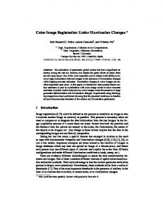
6 Illustrations In this section, we illustrate the three gamut clipping techniques for luminance histogram equalization. In luminance histogram equalization, the luminance component of the original image is retrieved and the luminance accumulated histogram is plotted. Based on the accumulated histogram, the histogram equalization is operated so that the resulted image will have a uniform histogram. Figure 11共a兲 shows the original image and Figs. 11共b兲, 11共c兲, and 11共d兲 show the result of RGB, luminance, and saturation clippings, respectively. It shows that clipping saturation produces an image result with the best contrast because each pixel is able to reach the expected luminance
Fig. 13 Illustration of saturation clipping on the red hue plane of the LHS space.
of the histogram equalization. The difference in contrast can be obviously seen on the faces and the hairs of the man and woman, the carpet, the couch, and the flowers. In clipping luminance, the hue and saturation is maintained but the luminance is changed to the clipped value. Using such an approach will not change the chromatic attributes but may lose the contrast on the image. Figure 12 illustrates the clipping of luminance for two pixels, P 1 ( 关 L,H,S兴 ⫽ 关 0.8,0 deg,0.6 兴 ) and P 2 ( 关 L,H,S兴 ⫽ 关 0.6,0 deg, 0.6 兴 ), on the red hue plane of the LHS space. Both of them are clipped to the same point, P 3 ( 关 L,H,S兴 ⫽ 关 0.427,0 deg, 0.6 兴 ), of the LHS space, where they have the same value of luminance 0.427, although they are originally different. If there are many pixels in a region of the image with different luminance values but very close values of saturation and hue, clipping their luminance values forces them to fall into a cluster with close values of luminance, hue, and saturation. Therefore, the contrast of this region is completely lost. Clipping the values of R, G, or B will change the luminance, hue, and saturation of the processed pixel completely in most cases. In particular, if the processed color is far away from the RGB color gamut, clipping the R, G, or B values changes the color significantly. Observing the illustration in Fig. 11, the result produced by clipping saturation has better contrast. Indeed, the allowable range of saturation decreases as the luminance increases. When the Table 1 Processing time of color image processing with the conventional or efficient technique.
Type of color image processing Luminance histogram equalization Luminance histogram stretching
Conventional technique (using forward and Efficient technique backward (using scaling transformations) and shifting) 2.2 sec
1.6 sec
1.9 sec
1.4 sec
Optical Engineering, Vol. 42 No. 3, March 2003
709
Yang and Kwok: Efficient gamut clipping . . .
luminance is in its maximum value, the only allowable value of saturation is zero and the color is pure white. Clipping saturation does not affect the image visually. Figure 13 illustrates saturation clipping. P 1 ( 关 L,H,S兴 ⫽ 关 0.8,0 deg,0.6 兴 ) and P 2 ( 关 L,H,S兴 ⫽ 关 0.6,0 deg,0.6 兴 ) with the same saturation but different luminance are clipped to P 3 ( 关 L,H,S兴 ⫽ 关 0.8,0 deg,0.117兴 ) and P 4 ( 关 L,H,S兴 ⫽ 关 0.6,0 deg,0.307兴 ), respectively. The luminance of P 1 and P 2 are kept but the saturation is clipped to the maximum allowed value. 7 Efficiency We conducted an experiment to compare the efficiency of the conventional technique 共using forward and backward transformation兲 and the efficient techniques 共bypassing forward and backward transformation by using scaling and shifting兲. Twenty images were processed by luminance histogram equalization and stretching. We measured the processing time taken by both techniques. The average of the processing times are shown in Table 1. It shows that the efficient technique reduces the processing time by 27%. 8
Derivation of Backward Transformation between RGB and LHS „LHS\RGB…
The backward transformation can be derived geometrically by two steps: 1. determining OP⬘ based on the values of hue and saturation, and 2. determining OP based on OP⬘ and the length of OP and OP⬘ . The derivation is as follows: assuming 0 deg⭐ ⬍120 deg, OQ⫽ 关 1⫺ 兩 QR 兩 cos 45 deg,1⫺ 兩 QG 兩 cos 45 deg,0兴 兩 RG 兩 ⫽& 710
Optical Engineering, Vol. 42 No. 3, March 2003
2 /3
冉
兩 QG 兩 ⫽ 兩 RG 兩 1⫺
冋
⬖OQ⫽ 1⫺
2 /3
冊
, ,0 2 /3 2 /3
册
OC⫽ 关 1/3,1/3,1/3兴 O P ⬘ ⫽OC⫹S 共 OQ⫺OC 兲 O P ⬘⫽
冋 冉
冊
冉
冊
1 2 3 3 1 1 1 ⫹ ⫺ S, ⫹ ⫺ S, 共 1⫺S 兲 3 3 2 3 2 3 3
册
⫽ 关 R * ,G * ,B * 兴 . Similarly, OP⬘ can be derived for 120 deg⭐ ⬍240 deg and 240 deg⭐ ⬍360 deg, O P ⬘⫽
Conclusion
RGB color coordinate systems are employed for color image representation in computer applications, such as storage, camera, scanner, etc. However, it does not correspond to human perception; therefore, color coordinate systems such as LHS and YIQ are usually utilized in color image processing. Unfortunately, many pixels cannot be mapped to the RGB color gamut after processing in the LHS or YIQ space. Clipping techniques are necessary to solve such a problem. Besides, the transformations between the RGB color coordinate system and the LHS or YIQ color coordinate system are complicated and time consuming. Efficient techniques are desired. We present the efficient techniques of luminance and saturation processing using LHS and YIQ. In addition, we present the efficient techniques for three gamut clipping techniques, RGB, luminance, and saturation clippings, using LHS and YIQ. Illustrations of the three clipping techniques are presented. Graphical analysis of luminance clipping and saturation clipping is also presented. Experiments to measure the efficiency of the conventional technique 共using forward and backward transformations兲 and the efficient technique 共using scaling and shifting兲 were conducted. It shows that the efficient technique reduces the processing time by 27%. 9
兩 QR 兩 ⫽ 兩 RG 兩
O P ⬘⫽
冋 冋 冉
冉
冊
冊
L L*
G⫽G *
B⫽B *
冊册 冊册
1 3 7 8 3 1 1 ⫺ S, 共 1⫺S 兲 , ⫹ ⫺ S ⫹ 3 2 3 3 3 3 2
L * ⫽0.299R * ⫹0.587G * ⫹0.114B * R⫽R *
冉 冉
1 5 3 3 4 1 1 S, ⫹ ⫺ S 共 1⫺S 兲 , ⫹ ⫺ 3 3 3 2 3 2 3
L L*
L L*
where L * ⫽0.299R * ⫹0.587G * ⫹0.114B * . If 0⭐H⭐2 /3,
冉 冉
冊
2 /3⫺H 1 1 ⫺ S R *⫽ ⫹ 3 2 /3 3
冊
H 1 1 G *⫽ ⫹ ⫺ S 3 2 /3 3 1 1 B * ⫽ ⫺ S. 3 3 If 2 /3⭐H⭐4 /3, 1 1 R *⫽ ⫺ S 3 3
冉
冊
4 /3⫺H 1 1 ⫺ S G *⫽ ⫹ 3 2 /3 3
Yang and Kwok: Efficient gamut clipping . . .
冉
冊
⫺2 /3⫹H 1 1 ⫺ S. B *⫽ ⫹ 3 2 /3 3
22.
If 4 /3⭐H⭐2 ,
冉
冊
⫺4 /3⫹H 1 1 R *⫽ ⫹ ⫺ S 3 2 /3 3 1 1 G *⫽ ⫺ S 3 3
冉
21.
23. 24. 25.
冊
2 ⫺H 1 1 ⫺ S. B *⫽ ⫹ 3 2 /3 3
Acknowledgment This project is supported by the Earmarked Grant for Research of the Hong Kong Research Grants Council, CUHK 7034-98E.
References 1. G. J. Braun and M. D. Fairchild, ‘‘Color gamut mapping in a huelinearized CIELAB color space,’’ Proc. 6th IS&T/SID Color Imaging Conf., pp. 147–152 共1998兲. 2. N. Katoh and T. Deguchi, ‘‘Reconsideration of CRT monitor characteristics,’’ Proc. IS&T/SID Color Imaging Conf., 5, 33– 40 共1997兲. 3. H. Kotera and K. Kanamori, ‘‘The new color image processing techniques for hardcopy,’’ Proc. SPIE 1075, 252–259 共1989兲. 4. M. R. Luo and B. Rigg, ‘‘BFD共l:c兲 colour difference formula, Part 1 and Part 2,’’ J. Soc. Dyers Colour 103, 126 –132 共1987兲. 5. J. J. McCann, ‘‘Color spaces for color-gamut mapping,’’ J. Electron. Imaging 8共4兲, 354 –364 共1999兲. 6. G. Marcu and S. Abe, ‘‘Gamut mapping for color simulation on CRT devices,’’ Proc. SPIE 2658, 308 –315 共1996兲. 7. M. Ito and N. Katoh, ‘‘Gamut compression for computer generated images,’’ Extended Abstracts of SPSTJ 70th Anniversary Symp. on Fine Imaging, pp. 85– 88 共1995兲. 8. N. Katoh, M. Ito, and S. Ohno, ‘‘Three-dimensional gamut mapping using various color difference formulae and color spaces,’’ J. Electron. Imaging 8共4兲, 365–379 共1999兲. 9. Colorimetry, CIE Publication NO. 15.2, Bureau Central De la CIE, Vienna 共1986兲. 10. R. Y. C. Wei, M. J. Shyu, and P. L. Sun, ‘‘A new gamut mapping approach involving lightness, chroma, and hue adjustment,’’ Proc. TAGA, 685–701 共1997兲. 11. F. J. J. Clarke, R. McDonald, and B. Rigg, ‘‘Modification to the JPC79 colour difference formula,’’ J. Soc. Dyers Colour 100, 128 –132 共1984兲. 12. G. J. Braun and M. D. Fairchild, ‘‘Image lightness rescaling using sigmoidal contrast enhancement functions,’’ Proc. SPIE 3648, 96 – 107 共1999兲. 13. M. Shimizu, S. Semba, S. Suzuki, and K. Murashita, ‘‘Gamut mapping algorithm suitable for implementation to device profiles,’’ Proc. 6th IS&T/SID Color Imaging Conf., 169–172 共1998兲. 14. L. W. MacDonald and J. Morovic, ‘‘Assessing the effects of gamut compression in the reproduction of fine art paintings,’’ Proc. 3rd IS&T/SID Color Imaging Conf., pp. 194 –200 共1995兲. 15. P. Laihanen, ‘‘Color reproduction theory based on the principles of color science,’’ IARAIGAI Conf. Proc. Advances in Printing Science and Technology 19, 1–36 共1987兲. 16. R. S. Ledley, M. Buas, and T. J. Golab, ‘‘Fundamentals of true-color image processing,’’ Proc. Int. Conf. Patt. Recog. 1, 791–795 共1990兲. 17. R. N. Strickland, C. S. Kim, and McDonnel, ‘‘Digital color image enhancement based on the saturation component,’’ Opt. Eng. 26共7兲, 609– 616 共1987兲. 18. J. D. Foley, A. van Dam, S. K. Feiner, and J. F. Hughes, Computer Graphics: Principles and Practice, Addision Wesley, Reading, MA 共1996兲. 19. H. Levkowitz and G. Herman, ‘‘GLHS: A generalized lightness, hue, and saturation color model,’’ CVGIP: Graph. Models Image Process. 55共4兲, 271–285 共1993兲. 20. J. J. Rodriguez and C. C. Yang, ‘‘High resolution histogram modifi-
26. 27. 28. 29.
cation of color images,’’ Graphical Models and Image Process. 57共5兲, 432– 440 共1995兲. D. H. Pritchard, ‘‘U.S. color television fundamentals—A Review,’’ IEEE Trans. Consumer Electron. 23, 467– 478 共1977兲. A. R. Robertson, ‘‘Historical development of CIE recommended color difference equations,’’ Color Res. Appl. 15, 167–170 共1990兲. A. R. Robertson, ‘‘The CIE 1976 color-difference formulae,’’ Color Res. Appl. 2, 7–11 共1977兲. J. J. Rodriguez and C. C. Yang, ‘‘Effects of luminance quantization error on color image processing,’’ IEEE Trans. Image Process. 3共6兲, 850– 854 共1994兲. C. C. Yang and J. J. Rodriguez, ‘‘Efficient luminance and saturation processing techniques for bypassing color coordinate transformations,’’ Proc. IEEE Int. Conf. Systems, Man, and Cybernetics, IEEE, New York, Vol. 1, pp. 667– 672 共1995兲. C. C. Yang and J. J. Rodriguez, ‘‘Efficient luminance and saturation processing techniques for color images,’’ J. Visual Commun. Image Represent 8共3兲, 263–277 共1997兲. B. A. Thomas, R. N. Strickland, and J. J. Rodriguez, ‘‘Color image enhancement using spatially adaptive saturation feedback,’’ Proc. Intl. Conf. Image Process. 3, 30–33 共1997兲. C. C. Yang and J. J. Rodriguez, ‘‘Saturation clipping in the LHS and YIQ color spaces,’’ Proc. SPIE 2658, 297–307 共1996兲. C. C. Yang and S. H. Kwok, ‘‘Gamut clipping in color image processing,’’ Proc. IEEE Intl. Conf. Image Process., IEEE, Piscataway, NJ, Vol. 2, pp. 824 – 827 共2000兲.
Christopher C. Yang is currently an associate professor in the Department of Systems Engineering and Engineering Management at the Chinese University of Hong Kong. From 1997 to 1999, he was an assistant professor in the Department of Computer Science and Information Systems and associate director of the Authorized Academic JavaSM CampusSM at the University of Hong Kong. He received his BS, MS, and PhD in electrical and computer engineering from the University of Arizona, Tucson, in 1990, 1992, and 1997, respectively. From 1995 to 1997, he was a research scientist in the Artificial Intelligence Laboratory in the Department of Management Information Systems, where he was an active researcher in the Illinois Digital Library project. The Illinois Digital Library project was one of six multimillion projects in the US Digital Library Initiative 1 from 1994 to 1998. From 1992 to 1997, he was also a research associate in the Intelligent Systems Laboratory in the Department of Electrical and Computer Engineering. His current research interests are digital library, Internet agents, information visualization, color image processing, constraint network, and computer integrated manufacturing and inspection. He has published more than 80 research papers in referred journals and conference proceedings. He was the chairman of the Association for Computing Machinery Hong Kong Chapter in 2000. He was also the program cochair of the First Asia Digital Library Workshop, and program committee and organizing committee member for several international conferences. He was an invited panelist of the NSF Digital Library Initiative II Review Panel, and Information Technology Research Review Panel. S. H. Kwok received a BEng (Hons) in electronic and communications engineering (1992) from the University of North London. He received his Diploma of Imperial College (DIC) (1997) from the Imperial College of Science, Technology and Medicine, and his PhD in digital image processing (1997) from the University of London. He is currently assistant professor at the Department of Information and Systems Management, Hong Kong University of Science and Technology (HKUST). He was a visiting scholar and a research assistant in the Department of Electronic and Information Engineering at the Hong Kong Polytechnic University (1994 to 1995).
Optical Engineering, Vol. 42 No. 3, March 2003
711