Waldemar Celes Tecgraf/PUC-Rio, Computer Science Department, Pontifical Catholic University of Rio de Janeiro, Rua Marquês de São Vicente 225, Rio de Janeiro, RJ, 22450-900, Brazil
Glaucio H. Paulino1 e-mail:
[email protected] Department of Civil and Environmental Engineering, University of Illinois at Urbana–Champaign Newmark Laboratory, MC-250, 205 North Mathews Avenue, Urbana, IL 61801-2397
Rodrigo Espinha Tecgraf/PUC-Rio, Computer Science Department, Pontifical Catholic University of Rio de Janeiro, Rua Marquês de São Vicente 225, Rio de Janeiro, RJ, 22450-900, Brazil
1
Efficient Handling of Implicit Entities in Reduced Mesh Representations State-of-the-art numerical analyses require mesh representation with a data structure that provides topological information. Due to the increasing size of the meshes currently used for simulating complex behaviors with finite elements or boundary elements (e.g., adaptive and/or coupled analyses), several researchers have proposed the use of reduced mesh representations. In a reduced representation, only a few types of the defined topological entities are explicitly represented; all the others are implicit and retrieved “on-the-fly,” as required. Despite being very effective in reducing the memory space needed to represent large models, reduced representations face the challenge of ensuring the consistency of all implicit entities when the mesh undergoes modifications. As implicit entities are usually described by references to explicit ones, modifying the mesh may change the way implicit entities (which are not directly modified) are represented, e.g., the referenced explicit entities may no longer exist. We propose a new and effective strategy to treat implicit entities in reduced representations, which is capable of handling transient nonmanifold configurations. Our strategy allows, from the application point of view, explicit and implicit entities to be interchangeably handled in a uniform and transparent way. As a result, the application can list, access, attach properties to, and hold references to implicit entities, and the underlying data structure ensures that all such information remains valid even if the mesh is modified. The validity of the proposed approach is demonstrated by running a set of computational experiments on different models subjected to dynamic remeshing operations. 关DOI: 10.1115/1.2052830兴 Keywords: Topological Data Structure, Reduced Representation, Implicit Entities, Finite Element Mesh
Introduction
Different topological data structures have been proposed for representing finite 共or boundary兲 element meshes 关1–8兴. Efficient access to adjacency information among the topological entities that compose the model is crucial to implement mesh generation algorithms 关9,10兴 and to support dynamic, adaptive analyses 关11–17兴. In fact, to be able to efficiently modify the mesh under the course of the simulation, one needs a data structure that provides computational efficiency for both querying adjacency topological relationships and applying remeshing operators. Moreover, due to the increasing size of the meshes currently being used 关18兴, different works have proposed the use of reduced 共or compact兲 mesh representations 关3–8兴. By using reduced representation, one tends to minimize mesh storage space, which in turn allows handling of large models required for simulating complex behaviors 共e.g., with finite elements or boundary elements兲. Despite being very effective in reducing the memory space needed to represent such large models, reduced representations face the challenge of ensuring the consistency of all information attached to implicit entities, especially when the mesh undergoes modifications. A reduced topological representation can be achieved by: 共i兲 implicitly representing adjacency relationships, and/or 共ii兲 implicitly representing topological entities. In either case, all implicit information has to be efficiently retrieved, as required, “on-thefly.” From the application point of view, there should be no difference in the way explicit or implicit information is handled. For 1 To whom correspondence should be addressed. Contributed by the Engineering Simulation and Visualization Committee for publication in the JOURNAL OF COMPUTING AND INFORMATION SCIENCE IN ENGINEERING. Manuscript received October 11, 2004. Revised August 1, 2005. Guest Editor: K. Shimada.
348 / Vol. 5, DECEMBER 2005
instance, an implicit adjacency relationship can be retrieved based on others explicitly stored; however, the client application should have access to any relationship without being aware of the difference in the internal representation. If a performance penalty for retrieving implicit relationships exists 共and it is usually the case兲, this penalty should be kept under reasonable limits—the time for retrieving any topological relationship should be proportional to the number of retrieved entities. Similarly, if topological entities are implicitly represented, an application should be allowed to freely list, access, attach properties to, and hold references to them. In an adaptive analysis, for instance, the underlying data structure has to ensure that all such attached information remains valid even if the mesh is modified. This is not a simple task: implicit entities are commonly described by references to explicit ones, and modifying the mesh may change the way implicit entities 共which are not directly modified兲 are represented 共e.g., the referenced explicit entities may no longer exist兲. This paper addresses the problem of managing reduced representations. Based on a novel and complete topological mesh data structure that explicitly represents only nodes and elements 关8兴, we propose a new and effective strategy to handle implicit entities 共such as edges and facets兲. Our strategy allows, from the application point of view, explicit and implicit entities to be interchangeably handled in a uniform and transparent way. The validity of the proposed approach is demonstrated by running a set of computational experiments on different models subjected to dynamic remeshing operations. The remainder of this paper is organized as follows: Section 2 describes previous work on topological data structures for mesh representation. Section 3 discusses important issues related to managing implicit entities. Section 4 briefly reviews the original reduced data structure of Ref. 关8兴 and introduces a compact indexbased representation for supporting large models. Section 5 pre-
Copyright © 2005 by ASME
Transactions of the ASME
Downloaded 24 Aug 2009 to 192.17.146.2. Redistribution subject to ASME license or copyright; see http://www.asme.org/terms/Terms_Use.cfm
sents the strategy to support dynamic remeshing. Finally, Sec. 6 presents an analysis of the proposed approach to manage reduced representation and, in Sec. 7, some concluding remarks are drawn.
2
Related Work
The use of topological data structures for representing and modeling solids was significantly advanced by Baumgart’s 关19兴 winged-edge data structure for representing manifold polyhedron surfaces. Since then, several different data structures have been presented for both manifold 关20,22兴 and non-manifold 关21,23–25兴 boundary representations or B-reps. They 共B-reps兲 are appropriate for representing geometric models, which, in general, are described by means of generalized polyhedron meshes, handling nonplanar edges and faces 关22兴. Attempts to use such sophisticated data structures for representing finite element meshes resulted in highly integrated frameworks 共from geometry modeling to mesh generation兲 关1,2兴; however, such topological data structures impose a prohibitive cost in storage space for representing large meshes. The constraints imposed by domain-based methods, e.g., finite element method, on the domain discretization call for the use of “lighter” topological data structures for mesh representation. Lightweight data structures are also essential for computer graphics where several approaches have taken advantage of the fixed topology of cells in both two-dimensional 共2D兲 and threedimensional 共3D兲 simplicial meshes 共triangular meshes, for 2D; and tetrahedral meshes, for 3D兲. Several proposals for representing such simplicial meshes make use of the fixed topology of each cell 共triangle or tetrahedron兲, thus achieving highly reduced representations 关26–29兴 while being able to retrieve all important topological adjacency relationships. Important works in this field include the development of topological data structures for multiresolution representation 关30–33兴, progressive transmission 关34兴, and mesh compression 关35兴. In these data structures, only vertices and cells 共triangles or tetrahedra兲 are usually explicitly represented, which is quite appropriate for computer graphics applications where only these entities need to be processed 共e.g., visualization applications only need access to the list of triangles or tetrahedra兲. The representation of finite or boundary element meshes 关36兴 may take inspiration from the data structures used for representing simplicial meshes. Two main differences should be considered. First, a general mesh representation has to support element types other than triangular or tetrahedral 共e.g., quadrilateral, hexahedral, pyramidal, and higher-order elements兲, including mixed models. This problem can be easily overcome with the use of element templates: each type of finite 共or boundary兲 element presents a fixed and known local topology that can be coded in templates 关3,5,6,8兴. The second, and more challenging, difference is related to the need of accessing topological entities other than nodes and elements. For instance, in finite element applications we need to define the relationship of the mesh against the geometric domain, an association called mesh classification 关3兴. Topological entities such as edges and faces have to store classification information, and such information has to be maintained through all meshrelated algorithms, including mesh generation and enrichment procedures 关5,6兴. Different representations have been proposed for managing finite element meshes, defining the model by means of a set of topological entities that includes, for 3D models, region, face, edge, and vertex 关3–7兴. In order to achieve reduced representations, the authors have opted for explicitly storing only a few sets of topological adjacencies, and not for explicitly storing faces and/or edges 关3,4兴. More recently, a different approach has been taken with the development of dynamic mesh representations that extract from a database an appropriate representation for specific needs whenever necessary 关5–7兴. In our previous work 关8兴, we have opted for using a different set of topological entities to be able to interchangeably work with
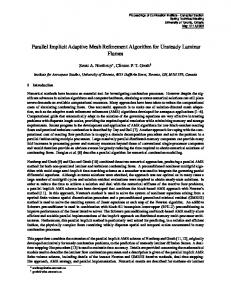
Fig. 1 Effect of an edge collapse operator on implicit entities: „a… the original model, „b… the modified model „see Ref. †3‡…. The edge ˆ2,6‰ is collapsed with vertex 6 replacing vertex 2; edge e ˆ2,4‰ and face f ˆ1,2,4‰ are changed to edge e⬘ ˆ4,6‰ and face f⬘ ˆ1,4,6‰, respectively. Each arrow indicates the selected entity orientation.
both 3D and 2D models: element, node, facet, edge, and vertex. Only elements and nodes are explicitly represented in our compact adjacency-based topological data structure. We also have introduced the use of oriented entities 关21兴 for finite element meshes, which, as we shall demonstrate, greatly simplifies the management of implicit entities.
3
Issues With Implicit Entities
Beall and Shephard 关3兴 have pointed out issues regarding reduced representation that turn the use of implicit entities cumbersome. The main problem arises when applying a remeshing operator, as implicit entities, which are not directly modified, may have their representations changed. This happens because the representations of implicit entities have to be anchored to explicit ones, i.e., their representations are based on references to explicit entities. Therefore, the representations of implicit entities are indirectly modified whenever the anchoring explicit entities are modified. The first question is then which representation to use for retrieving implicit entities. Each implicit entity has to be represented in a consistent and unambiguous way, ensuring uniqueness in equality tests. Previous works 关3–6兴 have opted for associating a unique identification number 共ID兲 for each vertex 共node兲 and for representing implicit edges and faces based on the IDs of their bounding vertices. Thus, each edge is represented by the IDs of its two bounding vertices, and each face is, directly or indirectly, represented by the IDs of its cyclic set of bounding vertices. Two entities are then considered equal if they are represented by the same set of IDs. In order to improve the performance of comparison operators, the IDs are stored in an ordered manner. The first ID is chosen as the lowest numeric ID in the set and, for faces, the second ID is chosen as the lowest numeric ID adjacent to the first one. However, by describing an entity using an ordered set of IDs, one is implicitly defining an orientation for such an entity, which imposes additional challenges when the mesh undergoes modifications. Thus, we do not adopt such approach in our present work. Beall and Shephard 关3兴 have illustrated the side effects of remeshing operators over implicit entities by applying an edge collapse operator to a 2D model, as shown in Fig. 1. Considering that edges and faces are implicitly represented as described above, two main problems arise: 共i兲 implicit, not directly modified, entities have their representation changed; and 共ii兲 implicit entities have their orientation changed. As illustrated in Fig. 1, the edge 兵2,6其 is collapsed, with vertex 6 replacing vertex 2. Before applying the operator, the edge e is represented by 兵2,4其, and the face f is represented by 兵1,2,4其 共Fig. 1共a兲兲. After the operator takes effect, the representation of edge e is changed to e⬘ 兵4,6其, and of face f to f ⬘ 兵1,4,6其, thus also changing their orientations.
Journal of Computing and Information Science in Engineering
DECEMBER 2005, Vol. 5 / 349
Downloaded 24 Aug 2009 to 192.17.146.2. Redistribution subject to ASME license or copyright; see http://www.asme.org/terms/Terms_Use.cfm
In the development of the mesh-oriented database 共MOAB兲 关7兴, the authors have opted for using opaque handles to represent entities. They have used a 4-byte word as a handle, using 4 bits to code the entity’s type and 28 bits to code the entity’s ID. By using handle instead of pointers to objects, one can freely 共and dynamically兲 change object representations without affecting client applications. The MOAB’s authors have mentioned that entities can have explicit or implicit representation. Recently, Tautges 关37兴 has described how semi-structured hexahedral meshes can be integrated in the MOAB system using a very compact implicit representation. However, for the general 共unstructured兲 case, it is not clear how implicit entities are managed and how IDs are assigned to such implicit entities. In order to keep the model consistent, any information stored in entities that are not directly modified should remain valid. Besides, if the client application holds a reference to such entities, it should be able to use that reference in future queries or operations on the model. The underlying data structure has to ensure, in a transparent way, that all references to implicit entities, which are not directly modified, remain valid. To our knowledge, such a framework has not been investigated in the literature. This paper presents a new and effective manner to handle implicit entities, in a way that the client application can freely manipulate entities, either explicitly or implicitly represented.
4
Reduced Topological Mesh Representation
In our previous work 关8兴, we have introduced a new reduced topological data structure for representing finite or boundary element meshes. The proposed data structure was designed to support, under the same framework, both 3D and 2D models, with manifold domains 关20兴. More precisely, the external boundary of a 3D mesh must have 2-manifold topology; therefore, each edge on the boundary is shared by exactly two boundary faces. Accordingly, for 2D models, the external boundary must have 1-manifold topology, with each vertex on the boundary having exactly two boundary edges connected to it. The data structure provides support for any type of element defined by templates of ordered nodes, which include all Lagrangian-type elements 共T3, T6, Q4, Q8, Tetra4, Tetra10, Hexa8, etc.兲; however, one cannot mix 3D and 2D elements in a single model at this stage. The mesh representation is complete, in the sense that all adjacency relationships among the defined topological entities can be retrieved in time proportional to the number of retrieved neighbor entities 关8兴. 4.1 Topological Entities. This data structure defines five topological entities: element, node, facet, edge, and vertex. The same set of topological entities is used to represent both 3D and 2D models. Element represents a finite 共or boundary兲 element of any type or order. Node represents a mesh node, including corner and midside nodes. Facet is defined as the interface between two elements. Accordingly, for 3D models, a facet corresponds to an entity of dimension two; while, for 2D models, it corresponds to an entity of dimension one. Edge defines the boundary of facets. Finally, vertex defines the boundary of edges, thus being associated to a corner node 共there are no vertices associated to midside nodes兲. Although redundant for 2D models, where each facet corresponds to one edge and vice-versa, the use of this set of topological entities has brought important benefits for the design and implementation of the data structure. It has allowed the conception of a unified framework for 3D and 2D models: the same algorithm 共i.e., same code兲 can be applied to any model, despite its dimension. As an example, this set of entities allows adopting the same procedure to insert cohesive elements along bulk element interfaces for both 3D and 2D fragmentation simulation models, based on topological classification of fractured facets 关8兴. The redundancy, referred above, does not impose any additional memory cost because, as we shall discuss, the entities are implic350 / Vol. 5, DECEMBER 2005
itly represented. De Floriani and Hui 关29兴 have demonstrated that encoding only vertices and the top simplexes of simplicial complex is advantageous to achieve reduced, and complete, representations. In the context of mesh representation, we have opted for encoding only nodes and elements, despite the model dimension. Accordingly, in the data structure, only elements and nodes are explicitly represented. Each element stores its node incidence and the set of adjacent elements,1 one for each element facet. If the element has facets on the mesh boundary, it is represented by storing a corresponding null adjacency reference. Each node, besides its geometric position, stores a reference to one of its incident elements. Based on the adjacency information stored at the elements, we are able to retrieve all adjacent elements to a node, provided that the mesh domain is manifold. The other three topological entities, facet, edge, and vertex, are implicitly represented. Different from previous proposals 关3–6兴, these three entities have no associated orientation—they are treated as nonoriented entities. The data structure also introduces three oriented entities, namely facet-use, edge-use, and vertex-use, which represent the use of facet, edge, and vertex by an element, respectively. The introduction of these oriented entities for mesh representation makes it possible to distinguish a nonoriented entity 共e.g., a facet兲 from the oriented use of that entity by an element 共e.g., a facetuse兲, which simplified the design, implementation, and use of the data structure 共see Ref. 关8兴 for a detailed discussion兲. Each finite element in isolation is composed by a set of facets, edges, and vertices. These local entities are labeled with local identification numbers 共local IDs兲. The topology of each element is known in advance and depends only on the element’s type 共e.g., T3, T6, Tetra4, Tetra10兲. Consequently, for each type of element, we define its element template 关3兴. Based on an element template, we can extract all adjacency relationships relating the local entities of such element type. The local facets, edges, and vertices of an element in isolation correspond, respectively, to the use of facets, edges, and vertices of the mesh by that element. Therefore, the element template provides access to adjacency relationships relating entity-uses within an element. The orientation of such entities is implicitly defined by the element template. The diagram presented in Fig. 2 shows the five defined topological entities together with their topological attributes, which allow the access of adjacency relationships. An “internal facet” has two associated uses, corresponding to the two interfacing elements, while an “external facet” has only one associated use, since it represents a boundary facet. For 2D models, each facet is mapped to a unique edge and each vertex has a cyclically ordered set of associated uses. For 3D models, each edge has a radially ordered set of associated uses and each vertex has an unordered set of associated uses. Facet, edge, vertex, and their associated uses are implicitly represented and retrieved, when required, “on-the-fly.” One important point of the data structure is that facet, edge, and vertex are treated as nonoriented entities. The absence of an implicitly defined orientation for these entities greatly simplifies their management, since one does not have to keep track of orientation changes when the mesh undergoes modifications. Moreover, the orientations associated to facetuses, edge-uses, and vertex-uses do not change due to a mesh modification operation. If an element is removed from the model, all its associated uses are also removed. Conversely, as long as the element using a referenced entity exists, the associated uses will also exist, without having their orientation changed. The incidence of an existent element may change, but its template, which defines the orientations of the entity-uses, is fixed. In order to easily handle these implicit entities, the data structure uses concrete types for their representation, thus being treated as ordinary values, similar to any other built-in type of programming languages 关38兴. By using concrete types, we can avoid the 1
Two elements are considered adjacent if they share the same facet.
Transactions of the ASME
Downloaded 24 Aug 2009 to 192.17.146.2. Redistribution subject to ASME license or copyright; see http://www.asme.org/terms/Terms_Use.cfm
Fig. 3 The 4-byte word layout to identify elements and implicit entities. The first 4 bits are only used for implicit entities.
4.2 Index-Based Representation. In our original implementation 关8兴, we had opted for storing the nodes and elements of a model using doubly linked lists, which facilitates the implementation of insertion and removal operations. Now, aiming at the representation of very large models, we have decided to use an array-based approach, which brings some useful benefits: • • • Fig. 2 Topological entities defined by the data structure: solid boxes indicate explicit entities and dashed boxes indicate implicit entities. The arrows illustrate access provided by the topological attributes stored at the entities. From an element, we have access to its node incidence, to its adjacent elements, and to the anchored facets, edges, and vertices; from a node, we have access to one of its incident elements; from a facetuse, edge-use, and vertex-use, we have access to the anchoring element; finally, from a facet, edge, and vertex, we have access to the corresponding entity-use associated to the anchoring element. Besides these direct topological accesses, the data structure makes use of element templates to extract topological relationships among the entity-uses associated to each element.
need of dynamic allocation while manipulating implicit entities, facilitating the management of entity uniqueness and lifetime. Each facet-use, edge-use, or vertex-use is represented by a reference to the associated element 共the one that uses it兲 and a local ID, indicating its position in the element template. Each facet, edge, or vertex is simply represented by one of its uses. In order to ensure uniqueness, only one use is elected to be the representative use of the corresponding entity 共facet, edge, or vertex兲. In other words, each facet, edge, or vertex is anchored to one element, and the use associated to the anchoring element is used to define the entity. To identify implicit entities and to ease their enumeration, within each element, we also store bit flags 共the anchors兲 that indicate which facets, edges, and vertices are being anchored by the element. Thus, given an element, we can easily extract the representations of the implicit entities that are anchored to it. For consistency purposes, the data structure ensures that the anchoring element of a vertex is the one pointed to by the corresponding node. Also, for nonlinear edges, the anchoring element of an edge is the one pointed to by the corresponding midside node共s兲. Thus, given a node, we have direct access to the corresponding vertex 共for a corner node兲 or edge 共for a midside node兲. One can argue that the anchor implicitly defines an orientation for the implicit entities 共inheriting the orientation of the anchoring use兲. However, no operation on the data structure relies on this 共implicit兲 orientation—the entities are treated as nonoriented. As a consequence, if this 共implicit兲 orientation changes, no special care is taken. Therefore, if the application needs to attach an oriented attribute to a nonoriented entity, the attribute orientation has to be explicitly stored, together with the attribute itself. An alternative would be to attach the attribute to a corresponding use, which is an oriented entity. This latter option is usually the best choice 共note that the orientation of an entity-use never changes兲.
The model as a whole needs much less memory to be represented due to the avoidance of memory fragmentation An extension to deal with out-of-core representation is greatly simplified By using array indices 共IDs兲 instead of pointers, we can represent both explicit and implicit entities in a uniform way
The nodes of the model are stored in an array. Thus, each node is represented by its numeric ID, which corresponds to its position in the node array. Elements of the same type are also stored in arrays 共there is one array for each type of element present in the model兲. The data structure manages the need for reallocation of such arrays, thus implementing dynamic arrays. A type ID is assigned to each type of element 共T3, T6, etc.; or Tetra4, Tetra10, etc.兲. This type ID assignment can be done statically or dynamically. When using the dynamic approach, the client application registers the types of elements in use. The data structure uses this type ID to access the element template and the corresponding array of elements. For representing each element, we have used an approach similar to the one used to define the handling of entities in the MOAB system 关7兴: an element is defined by a 4-byte word, 4 bits being used to encode the element type ID and 24 bits to encode the element ID 共its position in the corresponding array兲. In this way, the data structure is able to handle 16 different types of elements within a single model and 16 million elements of a given type. The remaining 4 bits of the word are used to code implicit entities. As mentioned above, each implicit entity is represented by one of its uses, and each use is represented by its associated element and a local ID. Thus, each facet, edge, and vertex is represented by the anchoring element and a local ID. As illustrated in Fig. 3, the local ID is encoded in the remaining 4 bits. As a result, all topological entities are represented in a uniform way using a single word. If one needs to extend the limits 共16 different types of elements in a model or 16 million elements of a given type兲 for supporting larger meshes, this can be done by using words of 64 bits. Differently from the MOAB system 关7兴, we have opted for not treating entities as opaque objects. For each topological entity we define a different 共concrete兲 class, all of them having the 4-byte word as the unique aggregate datum. By using different classes for different entities, we are able to use the compiler’s type checking and to extend the entity representation without affecting the client application, what may be needed in a future version. 4.3 Handling Implicit Entities. From the client application point of view, there should be no difference in the way explicit and implicit entities are handled. The application has to be able to access, enumerate, hold reference to, and attach properties to implicit entities in the same way as it does with explicit ones. In the proposed data structure, implicit entities can be accessed as a result of an adjacency querying operation or via entity enumeration. For enumerating all facets, edges, or vertices without duplication, we traverse all elements and, for each element, we collect all facets, edges, or vertices which are anchored to the current
Journal of Computing and Information Science in Engineering
DECEMBER 2005, Vol. 5 / 351
Downloaded 24 Aug 2009 to 192.17.146.2. Redistribution subject to ASME license or copyright; see http://www.asme.org/terms/Terms_Use.cfm
element. Thus we are able to traverse all implicit entities in time proportional to the number of elements 关8兴. Once the application has access to an implicit entity, it can store its value for future use—the data structure ensures its validity and uniqueness. It is important to note that each time an implicit entity is accessed, its corresponding value 共concrete type兲 is returned. Thus, enumerating all entities is an operation that does not impose any memory allocation or entity creation. Conceptually, the entities, although not explicitly stored, always exist. When required, its representation 共a numeric ID兲 is returned. Another important issue is how to associate data with topological entities. It is straightforward to provide the client the ability to associate data with explicitly represented entities. It suffices to add a generic pointer 共void*兲 to each internal entity representation and give the client access to such pointer. As the entities are stored in arrays and identified by numeric IDs, another valid strategy is to allocate all client data in an array parallel to the one used to store the entities, thus reducing memory fragmentation. In order to further reduce the required storage space, one can use a hash table instead of an array. The use of a hash table imposes a performance penalty to access the data, but it brings a significant gain in memory use because the storage space is proportional to the amount of associated data stored, not to the number of entities. For instance, in an application that needs to classify the nodes against the model’s geometry, the use of hash drastically reduces the amount of memory space used, because only the boundary nodes need to have associated data. In our data structure, as implicitly represented entities are also identified by numeric IDs 共the 4-byte words兲, the use of a hash table to store the associated data is the natural choice. In fact, we have opted for storing associated data in hash tables, treating both explicit and implicit entities in the same and uniform manner 共we need a different hash table for each type of topological entity because different entities may have the same numeric ID; for instance, a facet may have the same ID as an edge兲.
5
Dynamic Remeshing Support
The major challenge of handling implicit entities is to maintain the consistency of the data structure when the mesh undergoes modifications. In order to support adaptive analysis, the data structure has to provide a set of topological operators, allowing the client application to request dynamic remeshing. Such operators modify the mesh locally, inserting, changing, and/or removing topological entities. For consistency, entities, which are not directly modified, could not have their representation changed; however, as implicit entities are anchored to explicit entities, modifying such anchoring explicit entities inevitably modifies the representation of the anchored implicit entities. The underlying data structure has to transparently, from the client application point of view, handle such representation changes. The client has to be able to hold a reference to an implicit entity in order to use it in a future operation, even if the entity’s representation changes due to a mesh operation. Moreover, all data associated to implicit entities have to be preserved if the entities are not directly modified. 5.1 Mesh Operators. Several local operators have been used for mesh modification, including mesh simplification and mesh refinement. The most popular operators are the ones based on edges, such as edge collapse, and its inverse operator, vertex split 关16,39兴. The advantage of edge-based operators is that they are simple and may be applied to both 3D and 2D simplicial meshes 共tetrahedral and triangular meshes兲. Other local operators, widely used to achieve multi-resolution schemes for 3D visualization, include element collapse, vertex removal, and polygon merging 关39兴. Such operators can also be applied to modify finite or boundary element meshes. Regardless of the operator used, the final mesh configuration should be valid; indeed, as the final configuration is known a priori, it can be validated before the operator is 352 / Vol. 5, DECEMBER 2005
Fig. 4 An edge collapse operator based on node and element removals and insertions: „a… original model; „b… all elements incident to a vertex are removed; „c… the isolated corresponding node is removed; „d… all removed elements, which were not adjacent to the collapsing edge, are reinserted with new connectivity
effectively applied 关16兴. After mesh modification, adaptive analysis usually requires an optimization process to improve the mesh quality according to a predefined metric. This is usually carried out by applying vertex displacement and, for 2D triangular meshes, by performing edge swaps 关40兴. Except for the vertex displacement, all others are topological operators, in the sense that they impose topological changes to the model by inserting/ changing/removing topological entities. In order to demonstrate the way implicit entities can be handled, instead of implementing a large set of specific topological operators, we have opted for working with four basic operators, which can be applied to any type of model • Node insertion: inserts a new isolated node in the model • Node removal: removes an isolated node from the model • Element insertion: inserts a new element in the model, given its node incidence • Element removal: removes an element from the model Other topological operators can be built on top of these four operators. An edge collapse, for instance, can be achieved by removing all elements incident to one of the edge vertices, removing the associated node, and then reinserting the elements that were not adjacent to the collapsing edge. Figure 4 illustrates this operation. However, it is easy to see that specific operators could be implemented more efficiently. Our goal here is just to discuss a strategy to maintain the consistency of implicit entities. 5.2 Nonmanifold Configurations. The data structure, as described so far, is capable of representing models with manifold boundary. However, during the course of a topological operation, the model can assume nonmanifold boundary configurations. Although the manifold configuration is restored by the end of the operation, the data structure has to be able to represent transient nonmanifold configurations. Figure 5 illustrates a nonmanifold configuration as a result of removing an element from the model. Similar configurations also arise if we construct the model from scratch, inserting each element at a time. Transactions of the ASME
Downloaded 24 Aug 2009 to 192.17.146.2. Redistribution subject to ASME license or copyright; see http://www.asme.org/terms/Terms_Use.cfm
Fig. 5 Nonmanifold configuration after element removal
For a model composed by a set of elements, only two nonmanifold configurations may arise: two nonadjacent elements in 3D sharing a same edge, and two non-adjacent elements, either in 3D or in 2D, sharing a same vertex. The former configuration represents a singularity at a non-manifold edge and the latter a singularity at a non-manifold vertex 关29兴, as illustrated in Fig. 6. In order to cope with such transient nonmanifold configurations, we have extended the original data structure. For each node, instead of keeping a unique reference to an incident element, we keep a list of references, each one to an incident element of each connected component adjacent to the node. This way, we are able to extract all elements incident to a given node. It is important to note, however, that the data structure is not complete for such non-manifold configurations, in the sense that it is not possible to retrieve all adjacency relationships as described in our previous work 关8兴. For instance, the radially ordered group of elements around a 3D edge with linear elements cannot be retrieved based uniquely on the topological information stored in the data structure. The goal here is to handle transient nonmanifold configurations to be able to restore the complete topological data structure when the manifold configuration is restored. For this purpose, it suffices to retrieve all incident elements of a given node: for each node in the list, we visit all adjacent elements of the corresponding connected component. Note that the existence of different edges or facets with the same set of bounding nodes does not necessarily imply in nonmanifold configurations. Figure 7 illustrates a 2D mesh with two different configurations. On the left 共Fig. 7共a兲兲, two distinguish edges share the same end nodes in a manifold configuration—it is topologically equivalent to a plate with a central hole. On the right 共Fig. 7共b兲兲, one of the shared nodes is on the boundary of the model, thus giving rise to a singularity at a nonmanifold vertex. Because the proposed data structure does not use the bounding nodes to represent implicit entities, the existence of different edges and/or facets sharing the same set of nodes in a manifold configuration is naturally supported. In fact, the occurrence of such manifold configurations is quite common in fragmentation simulations 关8兴, and not supporting them would be a major shortcoming of the data structure.
Fig. 6 Two distinct edges of a 2D mesh, sharing the same bounding nodes, may result in different configurations: „a… a manifold-configuration and „b… a nonmanifold configuration
Fig. 7 Two distinguished edges of a 2D mesh sharing the same bounding nodes may result in different configurations: „a… a manifold-configuration and „b… a nonmanifold configuration
5.3 Implicit Entity Lifetime. The proposed data structure has been designed for representing models described by a set of nodes and elements. We assume the absence of wire edges or dangling faces in the model, which is needed because an implicit entity can only appear as the boundary of an element. This decision should not impose any restriction to the support of adaptive analysis. In fact, the topological operators, which are usually used for mesh simplification and refinement, result in a valid model under this assumption. We then define the lifetime of implicit entities 共facet, edge, and vertex兲 in the following way: an implicit entity exists as long as at least one of its uses exists, i.e., the entity exists if and only if it has an incident element. Therefore, an isolated node does not define a vertex 共in fact, a vertex has been defined by a corner node, so it presumes the existence of an element兲. Accordingly, if all incident elements to a given vertex are deleted, the vertex is assumed to be deleted as well, and similarly for edges and facets. As a consequence, applying a mesh operator can lead to undesired side effects. Consider the 2D example illustrated in Fig. 4. If, for instance, the facet bounded by the nodes 3 and 5 was on the boundary of the model, removing the elements incident to node 2 would also remove the facet. When the new elements are inserted, a new facet would be defined, but, if the original one had an attribute attached to it, the attribute would be lost. In order to overcome this limitation, we allow an implicit entity to be locked. A locked entity is never removed. With this mechanism, we can preserve the boundary facet mentioned above. We lock the facet before removing the elements, unlocking it at the end of the operation 共after inserting the new elements兲. A more interesting approach consist of allowing the data structure to automatically lock/unlock implicit entities. The automatic locking mechanism preserves all implicit entities with attached attributes, by locking them before removing their last adjacent elements and releasing the lock as soon as new adjacent elements are inserted. In the proposed data structure, the client application can opt for explicitly locking the entities or enabling the automatic mechanism. The locking is implemented by creating the concept of virtual elements. The last element adjacent to a locked entity is not removed from the data structure, but just unlinked from the model. In other words, it becomes a virtual element that is not part of the model, but is internally stored only to anchor locked entities. If the entity is explicitly unlocked, the corresponding anchor in the virtual element is released, and the element is removed from the data structure if there is no other entity anchored to it. The anchor in a virtual element is automatically released if any other element adjacent to the locked entity is inserted in the model. It is important to note that this is not a formal instrument to represent dangling edges and facets or isolated vertex, but a mechanism to preserve the boundary of an element during a mesh modification. It is also important to observe that, for the particular example illustrated in Fig. 4, the implementation of a specific edge collapse operator for simplicial meshes would completely eliminate the problem, because the adjacent element would never
Journal of Computing and Information Science in Engineering
DECEMBER 2005, Vol. 5 / 353
Downloaded 24 Aug 2009 to 192.17.146.2. Redistribution subject to ASME license or copyright; see http://www.asme.org/terms/Terms_Use.cfm
be removed; only its incidence would be updated. As mentioned above, the purpose of not using such specialized operator is to illustrate how to manage the lifetime of implicit entities in the general case. 5.4 Implicit Entity Management. Our goal is to allow the client application to reference implicit entities in the same way as it does with explicit ones. Therefore, the client can use any reference to an implicit entity as long as it exists. Accordingly, it is considered an invalid operation to access an entity that has already been deleted from the model 共as it is invalid to access a deleted explicit entity兲. The challenge lies in the fact that an implicit entity, although yet alive, can have its representation changed due to a mesh modification. For instance, if the anchoring element of a facet, an edge, or a vertex is removed from the model, the anchored entity has its representation changed: it is then anchored to another incident element. However, the data structure has to ensure that the old representation also remains valid as long as the entity exists, because the client application can be holding a reference to the entity using this old representation. In order to accomplish such a task, we propose a strategy that keeps track of all representation changes. Whenever an entity representation is changed, the data structure stores a mapping from the old to the new representation. Moreover, all data associated to the old representation are transferred to the new one. If the client accesses the data structure using the old representation, this representation is internally mapped to the corresponding new one, which is then used to effectively access the data. The mapping is implemented with the use of a hash table, the mapping table. This strategy imposes a performance penalty that corresponds to accessing the mapping table whenever an implicit entity is passed as a parameter to an operation. However, as in this table both keys and values are implicit entities, which are identified by single words 共as previously described兲, the mapping access can be done very efficiently. The data structure maintains the mapping as long as the corresponding entity exists. If the entity is deleted 共for instance, by deleting all incident elements兲, the mapping has no longer to be maintained. In order to be able to remove the mapping, we also store a reverse mapping table, which maps the new representation to the old one. As an example, consider a cross section of an edge in a 3D model, as illustrated in Fig. 8. The edge has four incident elements 兵E1 , E2 , E3 , E4其, thus having four corresponding associated edgeuses 兵e1 , e2 , e3 , e4其, as shown in Fig. 8共a兲兲. Without loss of generality, consider that E1 is anchoring the edge 共Fig. 8共b兲兲; therefore, the edge is represented by e1 共the anchoring use兲. If the element E1 is then deleted from the model, the data structure detects that it is anchoring the edge and selects another adjacent element to be the new anchor. Let us assume that element E4 is chosen. An entry is then created in both the mapping table 共e1 → e4兲 and the reverse mapping table 共e4 → e1兲, as shown in Fig. 8共c兲兲. Now, consider that element E2 is removed, and then element E4 is removed. When the element E2 is removed, no mapping relating to the edge is needed because the element is not its anchor 共Fig. 8共d兲兲. However, when element E4 is removed, the data structure selects element E3 as the new anchor and adds another entry in both tables, i.e., mapping 共e4 → e3兲 and reverse mapping 共e3 → e4兲 tables, as shown in Fig. 8共e兲兲. By using this configuration, the client is allowed to access the model through references to both e1 and/or e4—the data structure maps both to the new representation e3. The representation e4 is directly mapped to e3, but e1 is first mapped to e4 and subsequently mapped to e3. In order to avoid this sequential mapping, we have used path compression in a way similar to the strategy used to compress the path in a union-and-find data structure: once e1 is mapped to e3, we update the mapping storing 共e1 → e3兲 in the place of 共e1 → e4兲. Thus, the mapping operation presents an amortized time complexity of constant order for practical situations 关41兴. Finally, if the client removes element E3, no element incident to the edge will remain. If the edge is not locked, 354 / Vol. 5, DECEMBER 2005
Fig. 8 An example of how implicit entities are managed, based on an edge shared by four different elements of a 3D model: „a… 3D schematic view of a cutting plane „ plane… crossing an edge shared by hexahedral elements; „b… the resulting crosssection of the edge and its 4 incident elements, with element E1 being the anchor of the edge „E denotes the anchor sign…; „c… element E1 is removed, thus adding new entries in the mapping and reverse mapping tables; „d… element E2 is removed, and no mapping related to the edge is needed because it is not the anchor; „e… element E4 is removed, adding new entries to the tables
it is deleted from the data structure as well, removing all its entries in both tables. This removal operation is accomplished by traversing the reverse mapping table. 5.5 Remarks on Implicit Entity Management. By using the above strategy, the client application can refer to an implicit entity as long as it exists. In fact, as described so far, the data structure maintains the corresponding entries in the mapping tables during the entire lifetime of the entity, even if the client application is not holding a reference to the entity. As a consequence, if the mesh is continuously modified, the data structure can inflate. Consider, for instance, the hypothetical situation in which the client continuously removes and re-inserts an element incident to an edge 共as illustrated in Fig. 8共b兲兲 in a cyclic order. The edge would never be deleted, and the mapping would be continuously updated, thus becoming very large. Although such a modification pattern should apparently not appear in a real application, continuous modification of large meshes can give rise to the same problem. We then have added a function that allows the client to explicitly request the data structure to release all mappings. After calling such a function, no old reference can be used to access the data structure. This kind of compression is also useful for saving the data structure in disk. In order to implicitly avoid inflating the mapping tables, we can implement a strategy to automatically collect the garbage: the mapping entries related to an entity are maintained if and only if Transactions of the ASME
Downloaded 24 Aug 2009 to 192.17.146.2. Redistribution subject to ASME license or copyright; see http://www.asme.org/terms/Terms_Use.cfm
the client application holds a reference to the corresponding entity; otherwise, there is no reason to keep the related mappings. The simplest garbage collection strategy consists of using a reference counter. Each time an entity is constructed, assigned, or copied, we increase its reference counter; each time the entity is destructed or overwritten, we decrement its counter. If the counter reaches zero, it means there is no remaining reference to the entity, and the entity mapping can be removed from the data structure. This strategy is easily implemented with C⫹⫹, using operator overload 关42兴. However, the reference counter strategy has a major drawback: it is not capable of dealing with cyclic 共recursive兲 references 关43兴. In the context of its use in the data structure, the strategy would fail 共i.e., would not remove all unreferenced entities兲 if the attribute attached to an entity A had a reference to entity B; and, conversely, the attribute of B had a reference to A. The client should be aware of that. Moreover, the reference counter strategy imposes a performance penalty on retrieving entities from the data structure. As the entities are not explicitly represented, the reference counter has to be implemented using a hash table. Then, whenever we need to update the counter, we have to access the hash. In Sec. 6, we show a few performance comparisons between using and not using reference counter. 5.6 Explicit Entity Management. The proposed data structure stores explicit entities 共nodes and elements兲 using arrays and these entities are represented by their position in such arrays 共entity IDs兲. Whenever a node or an element is removed, its ID can be reused to store another entity. In the case of a node, if the client requires it to be removed, the corresponding ID can be immediately reused to store another node. In contrast, after the client requires an element to be removed, in general the corresponding ID is not immediately available to be reused. The data structure has to ensure the uniqueness of all implicit entities that are stored in the mapping tables. Therefore, an element ID will only be available for reuse when it is no longer referenced by any implicit entities that are still alive. In the example illustrated in Fig. 8, for instance, just after removing element E1, its ID cannot be reused because one of its associated uses 共e1兲 is stored in the mapping tables 共Fig. 8共c兲兲. In fact, its ID will only be available for reuse after removing element E3 共considering, of course, that the element E1 is not anchoring any other entity兲. Another important issue is related to the order in which the available IDs are reused. The simplest strategy would use a stack to store all available IDs, implementing a last in, first out strategy. A more appropriate approach would use a priority queue 共a heap兲 that would return the smallest available ID. The use of a heap tends to pack the entities in the first positions of the array, thus improving performance, since only that portion of the array needs to be accessed for traversing the model. This same strategy is used to process birth and death of particles in large scale physical simulations 关44兴.
6
Table 1 Average elapsed times „in seconds… for constructing the model from scratch, inserting each element at a time
6.1 Construction From Scratch. The first computational experiment demonstrates that the element insertion operator uses the topological information stored in the data structure, thus having local effect. Therefore, the computational time needed to perform an element insertion is of constant order, despite the size of the model. In order to test such local behavior we used the operator to construct a finite element model from scratch, inserting each element at a time. We first insert all nodes in the data structure and then insert each element given its incidence. The element adjacency is inferred based on the bounding nodes of each element facet: for each new inserted facet, we search for an existing one with the same set of nodes among the facets adjacent to a given node. Thus, this particular operator presumes the absence of different facets sharing the same set of bounding nodes; although, as previously discussed, the data structure itself is capable of handling such configuration. We have run this test on models with different numbers of elements, for both linear and quadratic meshes. The models represent a 3D regular grid decomposed into six linear or quadratic tetrahedral elements per voxel. Table 1 shows the average elapsed time spent for constructing the whole model from scratch 共including the time spent to read the data from the disk兲, together with the amount of memory needed to store the model. As shown in Fig. 9, the average elapsed time needed to perform all operations is linearly proportional to the number of elements inserted, for both linear and quadratic models. This result demonstrates that the insertion of elements is based on local topological procedures, thus its performance is independent from the size of the model.
Computational Experiments
We have set up a few computational experiments in order to test the correctness, effectiveness, and efficiency of the data structure for supporting dynamic remeshing. For reference, the tests were done using the gcc 3.2 compiler with a Linux kernel 2.4 operating system, running on an Intel Pentium 4 CPU 2.53 GHz machine. Along with the elapsed time spent to perform the corresponding operations, we have annotated the minimal amount of memory needed to store the whole data structure, which includes the memory used to store the explicit entities 共nodes and elements, including virtual and referenced elements兲, the mapping tables, the locking table, the reference counter table, and the attribute tables. In practice, the amount of used memory is larger than the minimal reported because the data structure stores all information in dynamic arrays, which usually are not totally full. For a comparison of the required storage space of the proposed data structure against other reduced mesh representations, see Ref. 关8兴.
Fig. 9 Plot of time „seconds… vs number of elements for model construction from scratch. The data were extracted from Table 1. The data points associated to the 64Ã 64Ã 64 models are outside the plotting window.
Journal of Computing and Information Science in Engineering
DECEMBER 2005, Vol. 5 / 355
Downloaded 24 Aug 2009 to 192.17.146.2. Redistribution subject to ASME license or copyright; see http://www.asme.org/terms/Terms_Use.cfm
Fig. 10 A 4-k variable resolution mesh covering a square domain: „a… original 4-element mesh topology; „b… model topology after splitting the bottom edge once; „c… model topology after splitting the bottom edge a second time
6.2 Mesh Refinement and Optimization. The main motivation for developing the new dynamic reduced data structure is to provide support for adaptive analysis. As a simple example, we have tested the new data structure for supporting the implementation of mesh refinement on a 2D model using triangular elements. For this test, the mesh topology was generated using a 4-k mesh, which presents variable resolution capability that is crucial for adaptive computation 关45兴. Figure 9 shows that, on a square domain, the mesh is composed uniquely by right isosceles triangles with valences 共or degrees兲 varying from 4 to 8, thus the name 4–8 mesh. Figure 10 illustrates the refinement process using such mesh topology. First, it shows the coarse 4-element mesh covering the entire domain 共Fig. 10共a兲兲. The bottom edge is split once 共Fig. 10共b兲兲 and then split a second time 共Fig. 10共c兲兲. In order to preserve the mesh composed by uniquely right isosceles triangles, the right edge is also split, thus ensuring a smooth transition along the variable resolution of the mesh. We have used such mesh topology to test the data structure for supporting dynamic mesh refinement. The example under consideration consists of a quarter-plate with a central hole 共Fig. 11兲. The goal is to implement an automatic refinement process based
Fig. 11 A simple example illustrating the support for mesh refinement along the circular edge. From left to right, and top to bottom: geometric model; initial mesh configuration; and four different meshes achieved by iteratively splitting the boundary edges and by applying a filter to accommodate the internal nodes.
356 / Vol. 5, DECEMBER 2005
on mesh classification. To accomplish that task, we set up an initial coarse mesh model. The boundary edges are classified against the geometry, allowing selective automated refinement of the mesh along the circular boundary. The refined configurations are achieved by iteratively splitting the boundary edges. The split edge operator is built on top of element removal and insertion operations: first, the two elements adjacent to the edge are removed, then the new node is inserted and, finally, the four new elements are inserted. The new inserted nodes are mapped to the boundary geometry based on the edge classification. The mesh is then submitted to an optimization procedure using a weighted Laplacian filter, displacing the internal nodes in order to improve the geometrical quality of the mesh, as described by Alliez et al. 关40兴. Figure 11 illustrates a few stages of the refinement process, demonstrating handling of classification attributes associated to implicit entities. 6.3 Model Destruction and Reconstruction. Important selected features of the data structure include: • • •
An extension to handle transient nonmanifold configurations that are originated by dynamic remeshing A novel locking mechanism that allows lifetime extension of implicit entities, whose attributes are preserved during mesh modification procedures Two different strategies to determine how long the implicit entities are maintained in the mapping tables. In the first strategy, all old representations are maintained during the whole entity lifetime, regardless of whether the client keeps reference to them or not. In the second strategy, the data structure automatically collects unreferenced entities, which can be implemented by adding a reference counter to each accessed entity. Although the reference counter strategy minimizes the use of memory space required by the mapping tables, it adds a considerable performance penalty for retrieving the implicit entities because the counters have to be stored in hash tables.
In order to test the above features, we consider a set of experiments on two different finite element models, which represent realistic and practical engineering examples. The first is a model used for fracture mechanics investigations of surface cracks in advanced materials 共e.g., functionally graded composition兲 under thermomechanical loading 关46兴. It is represented by a quadratic hexahedral mesh with degenerated 共collapsed兲 elements surrounding the crack front. In order to ensure topological consistency, the degenerated elements were implemented by a different type of element 共the pentahedral element兲. The second represents a linear hexahedral mesh of the Titan IV solid rocket motor used for investigating the deformation experienced by the rocket propellant in the vicinity of the joints, using a geometric nonlinear dynamic analysis 关47兴. The mesh models are illustrated in Fig. 12. For performance comparison between “using” and “not using” reference counter to manage entity lifetime, we measured the average time needed to enumerate all the entities in the models. As can be seen in Table 2, without using the reference counter strategy, the time needed to traverse the implicit elements is similar to the time needed to traverse the elements. The reference counter strategy demands more processing time to traverse implicit entities, since the counters have to be updated each time an entity is retrieved from the data structure. In order to compare the performance while editing the model, and also to demonstrate the data structure ability to handle complex nonmanifold configuration, we set up the following experiment: given each model, we remove half of its elements, one element at a time, in a random order. Figure 13 illustrates the configuration of the models after removing half of their elements. Then, we reconstruct the model, reinserting each element at a time, again in a random order, thus recovering the initial configuration. To test the locking mechanism, we attach an attribute to Transactions of the ASME
Downloaded 24 Aug 2009 to 192.17.146.2. Redistribution subject to ASME license or copyright; see http://www.asme.org/terms/Terms_Use.cfm
Fig. 12 Models used on the numerical tests: top, surface crack model with quadratic hexahedral and pentahedral mesh; bottom, Titan IV solid model with linear hexahedral mesh
each boundary facet of the models 共represented either by the yellow color, or light gray in the B&W version, in Figs. 12 and 13兲, and then run the experiment with two different scenarios. In the first scenario, the boundary facets are not locked. As a result, the attributes attached to the removed facets are lost and the reconstructed model results in several boundary facets without attributes 共Fig. 14兲. In the second scenario, all boundary facets are locked before removing the elements. As a consequence, the data structure is able to reconstruct the model preserving all the original boundary facets, recovering the models of Fig. 12 with their original attributes. For comparison, the experiments are considered “using” and “not using” the reference counter strategy in both scenarios. Table 3 shows the average elapsed time for removing and reinserting the elements. As can be noted, the reference counter strategy brings benefits while removing the elements, because it maintains the mapping tables with minimum sizes, thus improving the hashing operations. During the reconstruction, the reference counter does not provide any advantage because there is no need to update the mapping tables while inserting elements. The locking mechanism introduces a negligible performance penalty, thus being quite ap-
Fig. 13 Model configurations after removing half of the elements in random order: top, surface crack model; bottom, Titan IV solid model
propriate for preserving implicit-entity attributes. Table 4 reports the memory needed for storing the whole Titan IV model when different features of the data structure are in use. The table shows the memory in three different configurations of the experiment: before removing the elements 共the original model with its boundary attributes兲, after removing half of the elements, and after reinserting the elements. Without the use of the reference counter strategy, the mapping tables inflate and demand more memory space for element storage because all element IDs referenced in the mapping tables cannot be reused. With the reference counter strategy, the memory needed for supporting the operations does not increase and, at the end, the reconstructed model uses the
Table 2 Average elapsed times „in seconds… for enumerating all topological entities of the models. The times reported are the average of a number of consecutive simulations.
Fig. 14 Model configurations after reconstructing the model without recovering the original boundary attributes: top, surface crack model; bottom, Titan IV solid model
Journal of Computing and Information Science in Engineering
DECEMBER 2005, Vol. 5 / 357
Downloaded 24 Aug 2009 to 192.17.146.2. Redistribution subject to ASME license or copyright; see http://www.asme.org/terms/Terms_Use.cfm
Table 3 Average elapsed times „in seconds… for destructing and reconstructing the models, by removing and reinserting half of the elements in random order
•
• same amount of memory as the original model. The memory needed to lock the boundary facets is quite small, again demonstrating the validity of the locking mechanism. As a final remark, the experiments have demonstrated advantages and disadvantages of using the reference counter strategy. On one hand, the strategy introduces a significant performance penalty for traversing the implicit entities; on the other hand, it reduces the amount of memory for modifying the mesh, thus improving performance. To eliminate the disadvantages, while preserving the advantages, the client application can explicitly control the reference counters. Each time the application needs to keep a reference to an entity for future use, it should explicitly add the entity counter 共e.g., by calling a function兲; whenever the reference is no longer in use, it should explicitly subtract the entity counter. In this fashion, no performance penalty is imposed for traversing the model and unreferenced entities is not maintained in the mapping tables.
7
Conclusion
We have introduced a new strategy for handling implicit entities in reduced mesh representations. From the client application point of view, implicit entities are handled in an efficient and transparent way. If the mesh undergoes modifications, the underlying data structure ensures that all data associated to implicit entities, which are not directly modified, are preserved. The proposed strategy is based on a few key concepts that have greatly simplified the implementation: •
Facet, edge, and vertex are nonoriented entities: there is no
Table 4 Amount of memory „in Mbytes… needed to store the Titan IV model in different configurations when using different features of the data structure
To support dynamic remeshing, we have extended our original data structure 关8兴 to handle transient nonmanifold configurations. As a consequence, despite the model configuration, topological operations are performed in time proportional to the number of local entities involved. The consistency of the data structure is ensured by mapping tables that keep track of all changes in the representation of implicit entities when the model undergoes modifications. The mapping related to an indirectly modified implicit entity is kept during its lifetime, thus allowing the client to use old references to access the data structure. We have investigated the use of reference counters in order to decide whether an entity mapping needs to be maintained. Although the reference counter strategy imposes a considerable performance penalty while retrieving information from the data structure 共e.g., for entity enumeration兲, its use is quite appropriate while editing the model, avoiding the data structure to inflate. An explicit control, by the client application, of the referenced entities seems to be a good alternative to avoid the performance penalty for accessing the data structure, while avoiding unreferenced entities to be maintained in the mapping tables. We have also proposed an efficient locking mechanism that allows the client application to preserve the boundary of elements during mesh modification. As a result, attributes attached to implicit entities can be preserved even if all anchoring elements are removed from the model. The robustness of the proposed data structure has been demonstrated by two practical engineering examples. The data structure is able to handle complex 共nonmanifold兲 configurations, as demonstrated by the examples in which half of the elements are removed, and then reinserted, in random order. The efficiency and effectiveness of the proposed locking mechanism have been illustrated by restoring the original model with all its attributes. To our knowledge, such framework provided by reduced mesh representation has not been presented in the literature. Finally, in the implementation of the proposed data structure, we have addressed a set of important issues that can be adapted for the implementation of other reduced mesh representations. They are indicated below: • • • • •
358 / Vol. 5, DECEMBER 2005
need to handle orientation changes, thus reducing the problem of ensuring model consistency. Facet-use, edge-use, and vertex-use, which represent the use of facet, edge, and vertex by an element, respectively, are oriented entities, but their lifetimes are strictly associated to the elements that use them. Implicit entities are defined by concrete types: by using concrete types, we can avoid the need for dynamic allocation while manipulating implicit entities, which are treated as ordinary values, similarly to any other built-in type of a programming language. Entities are identified by a 4-byte word: besides being a compact representation, the use of a 4-byte word allows efficient hashing evaluations. This improves performance, while treating both explicit and implicit entities in the same and uniform way.
Use of a 4-byte word to identify all entities, despite being explicitly or implicitly represented 共similar to the MOAB system 关7兴兲 Use of hash tables to store all data related to implicit entities, and to store attributes attached to explicitly represented entities Use of a heap in order to reuse available IDs, thus achieving a compact array-based representation 共as mentioned in Ref. 关44兴兲 Use of concrete types to represent implicit entities, thus avoiding dynamic allocation and facilitating the management of entity uniqueness and lifetime Use of reference counter to manage references to implicit entities Transactions of the ASME
Downloaded 24 Aug 2009 to 192.17.146.2. Redistribution subject to ASME license or copyright; see http://www.asme.org/terms/Terms_Use.cfm
Acknowledgments G.H.P. gratefully acknowledges the support from NASA-Ames, Engineering for Complex Systems Program, and the NASA-Ames Chief Engineer, Dr. Tina Panontin, through Grant No. NAG 2-1424. He also acknowledges additional support from the National Science Foundation 共NSF兲 under Grant No. CMS-0115954 共Mechanics & Materials Program兲. R.E. is financially supported by the Brazilian agency CAPES 共Coordenação de Aperfeiçoamento de Pessoal de Nível Superior兲. W.C. and R.E. would like to thank the support for conducting this research provided by the Tecgraf laboratory at PUC-Rio, which is mainly funded by the Brazilian oil company, Petrobras. The authors thank Dr. M. C. Walters for providing the fracture mechanics model and Dr. Ali Namazifard from the Center for Simulation of Advanced Rockets 共CSAR兲 for the Titan IV model 共of Sec. 6兲. The authors also thank the valuable contributions given by the anonymous reviewers.
References 关1兴 Wawrzynek, P. A., and Ingraffea, A. R., 1987, “Interactive Finite Element Analysis of Fracture Processes: An Integrated Approach,” Theor. Appl. Fract. Mech., 8, pp. 137–150. 关2兴 Martha, L. F., Wawrzynek, P. A., and Ingraffea, A. R., 1993, “Arbitrary Crack Representation using Solid Modeling,” Eng. Comput., 9, pp. 63–82. 关3兴 Beall, M. W., and Shephard, M. S,. 1997, “A General Topology-Based Mesh Data Structure,” Int. J. Numer. Methods Eng., 40, pp. 1573–1596. 关4兴 Garimella, R. V., 2002, “Mesh Data Structure Selection for Mesh Generation and FEA Applications,” Int. J. Numer. Methods Eng., 55, pp. 451–478. 关5兴 Remacle, J.-F., Karamete, B. K., and Shephard, M. S., 2000, “Algorithm Oriented Mesh Database,” Proceedings of 9th International Meshing Roundtable, Sandia National Laboratories, pp. 349–359. 关6兴 Remacle, J.-F., and Shephard, M. S., 2003, “An Algorithm Oriented Mesh Database,” Int. J. Numer. Methods Eng., 58, pp. 349–374. 关7兴 Tautges, T., Ernst, C., Merkley, K., Meyers, R., and Stimpson, C., 2004, “MOAB, A Mesh-Oriented Database,” Sandia National Laboratories Report SAND2004-1592, Sandia National Laboratories, Albuquerque, New Mexico 共http://cubit.sandia.gov/MOAB兲. 关8兴 Celes, W., Paulino, G. H., and Espinha, R., 2005, “A Compact AdjacencyBased Topological Data Structure for Finite Element Mesh Representation,” International Journal for Numerical Methods in Engineering 共in press兲. 关9兴 Löhner, R., 1988, “Some Useful Data Structures for the Generation of Unstructured Grids,” Commun. Appl. Numer. Methods, 4, pp. 123–135. 关10兴 Owen, S. J., and Shephard, M. S., 2003, “Editorial: Special Issue on Trends in Unstructured Mesh Generation,” Int. J. Numer. Methods Eng., 58, pp. 159– 160. 关11兴 Paulino, G. H., Menezes, I. F. M., Neto J. B. C., and Martha, L. F. R. C., 1999, “A Methodology for Self-Adaptive Finite Element Analysis—Towards an Integrated Computational Environment,” Comput. Mech., 23共5-6兲, pp. 361–388. 关12兴 Carey, G. F., Sharma, M., and Wang, K. C., 1988, “A Class of Data Structures for 2-D and 3-D Adaptive Mesh Refinement,” Int. J. Numer. Methods Eng., 26, pp. 2607–2622. 关13兴 Hawken, D. M., Townsend, P., and Webster, M. F., 1992, “The Use of Dynamic Data Structures in Finite Element Applications,” Int. J. Numer. Methods Eng., 33共9兲, pp. 1795–1811. 关14兴 Pandolfi, A., and Ortiz, M., 1998, “Solid Modeling Aspects of ThreeDimensional Fragmentation,” Eng. Comput., 14, pp. 287–308. 关15兴 Pandolfi, A., and Ortiz, M., 2002, “An Efficient Adaptive Procedure for ThreeDimensional Fragmentation Simulations,” Eng. Comput., 18, pp. 148–159. 关16兴 Frey, P. J., 2000, “About Surface Remeshing,” in Proceedings of the 9th International Meshing Roundtable, pp. 123–136. 关17兴 Vorsatz, J., Rössl, C., and Seidel, H.-P., 2003, “Dynamic Remeshing and Applications,” J. Comput. Inf. Sci. Eng., 3, pp. 338–344. 关18兴 Glimm, J., 2001, “The Terascale Simulation Tools and Technology 共TSTT兲 Center,” http://www.tstt-scidac.org, Executive Summary, 2001. 关19兴 Baumgart, B., 1972, “Winged-Edge Polyhedron Representation,” Technical Report CS-320 Stanford Artificial Intelligent Laboratory, Stanford University. 关20兴 Mäntylä, M., 1988, An Introduction to Solid Modeling, Computer Science Press, Rockville, MD. 关21兴 Weiler, K., 1986, “Topological Structures for Geometric Modeling,” Ph.D. thesis, Rensselaer Polytechnic Institute, New York.
关22兴 Chen, J., and Akleman, E., 2000, “Topologically Robust Mesh Modeling: Concepts, Data Structures, and Operations,” Int. J. Shape Model., 5共2兲, pp.149– 177. 关23兴 Weiler, K., 1988, “The Radial Edge Structure: A Topological Representation for Non-Manifold Geometric Boundary Modeling,” Geometric Modeling for CAD Applications, J. L. Encarnação, H. W. McLaughlin, ed., Elsevier Science Publishers, Amsterdam, pp. 3–36. 关24兴 Lee, S. H., and Lee, K., 2001, “Partial Entity Structure: A Compact NonManifold Boundary Representation Based on Partial Topological Entities,” Proceedings of the sixth ACM Symposium on Solid Modeling and Applications, pp. 159–170. 关25兴 Lee, S. H., and Lee, K., 2001, “Partial Entity Structure: A Compact Boundary Representation for Non-Manifold Geometric Modeling,” J. Comput. Inf. Sci. Eng., 1共4兲, pp. 356–365. 关26兴 Campagna, S., Kobbelt, L., and Seidel, H.-P., 1999, “Directed Edges—A Scalable Representation for Triangle Meshes,” Journal of Graphics Tools, 4共3兲, pp. 1–12. 关27兴 Rossignac, J., 1999, “Edgebreaker: Connectivity Compression for Triangle Meshes,” IEEE Trans. Vis. Comput. Graph., 5共1兲, pp. 47–61. 关28兴 Cignoni, P., De Floriani, L., Magillo, P., Puppo, E., and Scopigno, R., 2003, “Selective Refinement Queries for Volume Visualization of Unstructured Tetrahedral Meshes,” IEEE Trans. Vis. Comput. Graph., 10共1兲, 29–45. 关29兴 De Floriani, L., and Hui, A., 2003, “A Scalable Data Structure for ThreeDimensional Non-Manifold Objects,” Eurographics Symposium on Geometry Processing, pp. 72–82. 关30兴 Cignoni, P., Montani, C., Puppo, E., and Scopigno, R., 1997, “Multiresolution Representation and Visualization of Volume Data,” IEEE Trans. Vis. Comput. Graph., 3共4兲, pp. 352–369. 关31兴 Kobbelt, L., Bareuther, T., and Seidel, H.-P., 2000, “Multiresolution Shape Deformations for Meshes with Dynamic Vertex Connectivity,” Proceedings of Eurographics ‘00, pp. 249–260. 关32兴 De Floriani, L., Magillo, P., Puppo, E., and Sobrero, D., 2002, “A MultiResolution Topological Representation for Non-Manifold Meshes,” Proceedings of Solid Modeling’02, pp. 17–21. 关33兴 Silva, F. G. M., and Gomes, A. J. P., 2003, “Adjacency And Incidence Framework—A Data Structure for Efficient and Fast Management of Multiresolution Meshes,” Proceedings of the 1st International Conference on Computer Graphics and Interactive Techniques, Melbourne, Australia, pp. 159– 166. 关34兴 Wang, H., and Li, J., 2000, “OctMesh—Interactive Mesh Browsing over the Internet,” International Conference on Information Technology: Coding and Computing (ITCC’00), pp. 104–108. 关35兴 Rossignac, J., 2001, “3D Compression Made Simple: Edgebreaker with Zip&Wrap on a Corner-Table,” IEEE International Conference on Shape Modeling and Applications, pp. 278–283. 关36兴 Sutradhar, A., and Paulino, G. H., 2004, “A Simple Boundary Element Method for Problems of Potential in Non-Homogeneous Media,” Int. J. Numer. Methods Eng., 60共13兲, pp. 2203–2230. 关37兴 Tautges, T. J., 2004, “MOAB-SD: Integrated Structured and Unstructured Mesh Representation,” Eng. Comput., 20, pp. 286–293. 关38兴 Stroustrup, B., 1997, The C⫹⫹ Programming Language, Addison-Wesley, Reading, MA. 关39兴 Luebke, D., Reddy, M., Cohen, J. D., Varshney, A., Watson, B., and Huebner, R., 2003, Level of Detail for 3D Graphics, Morgan Kaufmann Publisher, Elsevier Science, San Francisco, CA. 关40兴 Alliez, P., Meyer, M., and Desbrun, M., 2002, “Interactive Geometry Remeshing,” ACM Trans. Graphics, 21共3兲, pp. 347–354. 关41兴 Cormen, T. H., Leiserson, C. E., Rivest, R. L., and Stein, C., 2001, Introduction to Algorithms, 2nd ed., The MIT Press, Cambridge, MA. 关42兴 Bulka, D., and Mayhew, D., 2000, Efficient C⫹⫹—Performance Programming Techniques, Addison-Wesley, Reading, MA. 关43兴 Knuth, D. E., 1997, The Art of Computer Programming, 3rd Edition, AddisonWesley; Reading, MA, Vol. 1. 关44兴 Latta, L., 2004, “Building a Million Particle System,” Game Developers Conference, March 22–24, San Jose, California. 关45兴 Velho, L., and Gomes, J., 2000, “Variable Resolution 4-K Meshes: Concepts and Applications,” Comput. Graph. Forum, 19共4兲, pp. 195–214. 关46兴 Walters, M. C., Paulino, G. H., and Dodds, R. H., 2004, “Stress Intensity Factors for Surface Cracks in Functionally Graded Materials Under Mode-I Thermomechanical Loading,” Int. J. Solids Struct., 41共3-4兲, pp. 1081–1118. 关47兴 Namazifard, A., and Parsons, I. D., 2004, “A Distributed Memory Parallel Implementation of The Multigrid Method for Solving Three-Dimensional Implicit Solid Mechanics Problems,” Int. J. Numer. Methods Eng., 61, pp. 1173– 1208.
Journal of Computing and Information Science in Engineering
DECEMBER 2005, Vol. 5 / 359
Downloaded 24 Aug 2009 to 192.17.146.2. Redistribution subject to ASME license or copyright; see http://www.asme.org/terms/Terms_Use.cfm