In conventional full duplex wireline systems digital echo .... In long DSL loops, for example, echo ..... discrete multitone asymmetric digital subscriber line.
EFFICIENT IMPLEMENTATION OF ECHO CANCELLER FOR APPLICATIONS WITH ASYMMETRIC RATES Alper Erdogan
Bijit Halder
Tzu-Hsien Sang
Ahmet Karakas
Koc University EE Department Istanbul, Turkey
Telicos Corporation Sunnyvale, CA, USA
National Chiao Tung Univ. EE Department Taiwan, R.O.C.
V.A. Sleep Research Center, Stanford Univ. CA USA
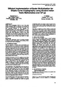
ABSTRACT In conventional full duplex wireline systems digital echo cancellers are commonly used to suppress echo. For applications with asymmetric rates the complexity and performance of the echo canceller depend on the implementation of the rate matching function. When the transmit rate is lower than the receive rate, traditional approach of resampling before filtering is inefficient. We show that efficient implementation can be obtained by reversing the order of resampling and filtering. We propose two new echo canceller structures based on scalar and vector error signals and develop associated adaptive algorithms. 1. INTRODUCTION In conventional wireline communication systems, a passive analog four-to-two wire conversion circuit, called hybrid, is used to achieve full duplex transmission over a single wire pair. If the hybrid circuit is not perfectly balanced, part of the transmit signal, known as the echo signal, leaks into the receive path and severely degrades the system performance. Unfortunately, in any real application the line characteristics are unknown and variable. Thus, there is always some imbalance in the hybrid circuit and the resulting echo signal. Digital echo cancellers (EC) are commonly used to suppress the echo signal. As shown in Figure 1, echo cancellation in digital domain is achieved in two steps: first, the transmit signal is used to generate a reliable copy of echo signal using a finite impulse response (FIR) EC filter; second, the copy of the echo signal is subtracted from the received signal. Note that the EC filter operates between the transmit and receive paths and must accommodate any rate difference between these two paths. For early full duplex wireline systems such as voice band modems, ISDN and HDSL, with symmetric data rates, i.e., identical transmit and receive rates, the implementation of EC filter is straightforward. However, for more recent applications that support asymmetric data rates, such as, ADSL[1] and VDSL[2], EC filter implementation must incorporate rate matching func-
tion. For applications with asymmetric rates, efficient design and overall performance of digital echo canceller depend on the implementation of the rate matching function. Rate R_tx
Transmit Filter (TXF)
Analog Front End (AFE) Single Twisted Wire Pair
Echo Cancellation Filter (ECF)
Analog Hybrid
_ Rate R_rx
Receive Filter (RXF)
+
Analog Front End (AFE)
Fig. 1. Block Diagram of Digital Echo Canceller In the conventional approach, as shown in Figure 2a, the transmit signal is first resampled to match the receive sampling rate before filtering. In this configuration, both the input and output of the EC filter, as well as, the output of the adder, called the error signal, are all sampled at the re���� samples per sec. As a result, conventional ceive rate adaptive algorithms can be used to train and update the EC filter. Moreover, for applications with higher transmit rate than receive rate, the resampling block down-samples the transmit signal and the EC filter operates at the lower receive rate. Thus, for such applications conventional configuration yields efficient design and we do not consider them any further. TXF
To AFE
R_tx
TXF
ECF
ReSampling Block
R_tx
R_rx
ReSampling Block
ECF
_ R_rx
To AFE
R_tx
From AFE RXF
a) Conventional
_ R_rx
From AFE RXF
b) Proposed
Fig. 2. Implementation of Rate Matching Function For applications with higher receive rate than transmit rate the situation is reversed. The transmit signal is up sam-
pled and the EC filter operates at the higher receive rate which results in an inefficient design. An EC filter operating at a higher receive rate increases the complexity of the echo canceller and the use of higher bandwidth error signal for training and update of the EC filter degrades the performance. An increase in the rate of EC filter operation results in a linear increase in the rate of computations for fixed EC filter length, and a linear increase in the length of the EC filter to generate a fixed length echo. The combined effect is quadratic increase in the computational complexity. Moreover, any increase in the EC filter length increases the size of hardware implementation or increases the memory size for software implementation. The increased EC filter length also increases the complexity of adaptive training and update algorithms. Note that the echo signal is a filtered version of the transmit signal and both signals have the same bandwidth which is smaller than that of the receive signal. Hence, it is possible to generate a copy of the echo signal from transmit signal using an EC filter that operates at the lower transmit rate. To achieve this goal, we propose that, unlike the conventional approach, first a copy of the echo signal is generated by the EC filter and then the output of the EC filter is up sampled to match the receive rate. In other words, order of the resampling block and the EC filter is reversed as shown in Figure 2b. This configuration requires the EC filter to operate at the lower transmit rate and thus yields efficient design. Due to the reduction in the overall complexity, we refer to the proposed structure as the Reduced Complexity digital EC (RC-DEC) structure. However, since the error signal needed for adaptation is sampled at the receive rate, conventional implementation of adaptive algorithms cannot be used. We propose two adaptive structures: one based on down sampled scalar error signal and the other based on vector error signal. We also developed associated adaptive algorithms and their efficient implementations. For Discrete MultiTone (DMT) systems there are frequency domain based approaches [3, 4, 5] that make efficient use of the lower bandwidth transmit and echo signals. These methods either assume that the echo channel spread is shorter than the prefix duration, which is not applicable for most real channels, or they make use of an additional multirate time domain filter. Furthermore, FFT unit in DMT demodulator is required to have higher bit resolution due the fact that the input of the FFT contains echo signal as well as the desired signal. In long DSL loops, for example, echo signal may even be greater in magnitude than the desired signal. In addition, these methods cannot be used outside of DMT systems. In contrast, the proposed RC-DEC structure and the associated adaptive algorithms are implemented in time domain and applicable to both DMT and single carrier systems. For the remainder of the paper, we assume that the higher
���
����
��� �
receive sampling rate multiple of the trans� , i.e.,is a��rational �� � where mit sampling rate and for co-prime integers and , which do not share any common factors. Next, we provide details of the proposed structure. The scalar case is presented first followed by the vector case.
� � �� ��
� � �
2. SCALAR STRUCTURE Due to the rearrangement of the EC filter and resampling block, as proposed in Figure 2b, the EC filter operates at the transmit rate but the error signal, the output of the adder, is generated at the receive rate. One approach to solve this problem of rate difference, which precludes the use of conventional adaptive algorithms, is to down sample the error signal. Note that only the echo component of the received signal, which occupies smaller bandwidth, is relevant for adaptation of EC filter and any component outside this band is extra noise. Thus, down sampling with appropriate antialiasing filter yields a new error signal that is sampled at the same rate as the transmit signal and is less noisy. A detailed block diagram of the echo canceller with down sampling is shown in Figure 3. The functions of the two resampling blocks are complementary and the interpolation filter (IPF) and the decimation filter (DCF) operate at the same rate, i.e., � . The decimation filter is used to filter signal times above the echo band.
�
�
x(m) To AFE
TXF
ECF ef (m)
Resampling Block
P
P
DMF (G)
IPF (F)
Q
Q
Resampling Block
_ e(n)
From AFE
y(n) RXF
Fig. 3. EC with down sampled error signal
�� ������� ��������� ��� ��������� �"!$#%�����'&(����� � � � where ������� is down sampled version of ��)$� at the output of the second resamling block, & is the EC filter coefficient
In order to derive an LMS update rule for the proposed stucture, we write the filtered error signal as
3. VECTOR STRUCTURE
vector,
�� ������ � � � ��� � � � ���������� � � � � � � �������� ��� � � � ���� � � � ���������� � .. .. ..
� � �.��� ��� � �!. ����"����. � � � ��#... �������� � � � is the ')(+* input data matrix, and � �-� , . �0/ � � . � � � � . �21 � � . �03 � �546464 . �0' � � �87 ! � &
$ %% %
�
is the filter coefficients vector that represents the combined effect of the interpolation filter 9 , decimation filter , as well as the effects of up-sampling and down-sampling blocks. Using the expression for the filtered error, we write the LMS gradient update equation as
&(���;: � � � &(�����= ��������� #%����� ! � �
where = is the step size. Since, is a Hankel matrix, computation of requires only * multiplications, instead of 0'?: �* , per iteration. Hence, 1@* multiplications are required per iteration for the proposed LMS update. Next, we use an approximation to obtain a simplified LMS update rule that needs only * multiplications.
#%�����
�
� � #%����� ! �
2.1. Simplified LMS Since, both the interpolation filter 9 and the decimation filter are low pass filters, they can be designed to have impulse response similar to sinc function with one dominant coefficient. Moreover, this property is preserved under convolution and inherited by . With that in mind, we make following two changes to : i) we replace the largest magnitude element of with its sign and, ii) set rest of the elements to zero. The first step is the rescaling of which can be absorbed in = . After rescaling, all the remaining elements have magnitude less than one and we approximate them by zero. Without loss of generality, we assume that nonzero element of is 1 and we get
�
�
�
�
Besides downsampling, the problem of rate difference can also be addressed by using a vectored error signal instead of scalar samples. Using vectored error signal, it is possible to utilize all samples of the error signal for training. In this section, we develop a stochastic gradient based training scheme that uses vectored error signal for the echo canceller in Figure 2b. We start with the observation that the rate matching block is a linear periodically time varying system. By defining the polyphase components of its output N 0O as
N
�0O � �
� �
N�PRQ�S �0OUT l � � nn ss � 0] � �>l � � nn ss .. . n C � � � �0] ��*�jp: � ��*�(k �>l � s .. o t . C � �0]q: � � � � � �>l � and & is the EC filter coefficient vector of length *�k . B�\
�
�
�BDA C! %# ����� � C ��� ��E � ��� ��E � � �GF6F6F C ��� ��E ��*H: � ��I � A where � is the approximate � and E is the index of the largest element of � . Using this approximation the LMS update simplifies to, &(���J: � � � &(�������-= ���������LK ��� ��E �MF
The simplified adaptation rule is just the normal LMS update applied to appropriately delayed input vector.
��
Q
O(0)
U (0)
P O(1)
P U
z
-1
Q
z-1
U (1)
R(z) U (Q-1)
z-Q+1
Q
O
O(P)
P
z-P+1
Fig. 4. Polyphase Rate Converter Block
� �0] � � r ss � �0] � � � � s � v"�0] �MF � . � � �0] � � ..� � : � � t
The error signal vector can be written as
u 0� ] �
� o
n
mnn
� ��)$�
As the high rate residual echo signal �� is a wide sense cyclostationary signal with period P, it is reasonable to choose the cost function as the square error function averaged over the period P, i.e., �
�u u � ��&(�0] � � � 0� ] � ! 0� ] �MF
Corresponding to this cost function, the gradient update algorithm for coefficients can be defined as
&(�0]q: � � �� P e S ��&(�0] � � � g u (& �0] �= e ` #%�0] aM� b! ! c 0� ] � � ����
�
�
where
�0] � ��
g
�0] � � B�#%
PRQ�S �0] �
(1)
P e S0f
P TXS �0] � I � (2)
is the��interpolated transmit signal matrix and P MS refers to � � F F F � � � ) phase vector of the signal � �0] � the l ( l�� C
�����
which is obtained by passing through indentical rate matching block that is used for the output of the echo canceller. Using Equation 2, we can rewrite update expression in Equation 1 as
&(�0] : � � � &(�0] �"�-=
T �
Q
��
� P MS �0] � P MS 0� ] �MF
x Resampling Block
Z -1
P
s(1)
s(2)
� � � � � �
�
4. CONCLUSIONS For wireline applications with lower transmit rate than the receive rate, traditional approach is inefficient. This is because resampling of the transmit signal to match the receive rate before filtering requires the EC filter to operate at the higher receive rate. We have shown that an efficient structure that requires the EC filter to run at the lower transmit rate can be obtained by reversing the order of filtering and resampling. However, such structure precludes the use of conventional training algorithms and we developed two new adaptive algorithms for the proposed new structure. We also provided simplified algorithm with complexity equal to the conventional training algorithm.
w
5. REFERENCES
Z -P+1 Resampling Block
P
�����
��
P ^�S �0] �_F6F6F
directions obtained from each C phase of the interpolated ver. The weight for each phase sion of the transmit signal is the corresponding error phase value. In Figure 5 we outline the structure corresponding to the method derived above. We note that this structure contains two identical resampling blocks. With this new structure the length of the adaptive filter is smaller, �� times, than the length of the conventional one. Such reduction in filter length yields: i) significant decrease in the hardware and software complexity; ii) increase in the convergence speed, and therefore, lower MMSE level in a limited training interval; iii) better conditioned input covariance, and therefore, better convergence behavior. The complexity increase due to rate matching blocks are negligible, as they can be implemented with fixed short fil��� with vectors used at each ters. Update rate is update. Therefore, the essential update rate is the same as the conventional approach.
[1] ITU-T G992.1, Asymmetric Digital Subscriber Line (ADSL) Transceiver, ITU-T Series, 1999.
P Z-1
s(P) P e (1) e
(2)
P
Z -P+1
[2] ITU-T G.993.1, Very-high-speed Digital Subscriber Line (VDSL) Transceiver, ITU-T Series, Under Development.
P P
+
P
+
Z -1
y
e (P)
+
P
Z -P+1
Fig. 5. Echo Canceller Structure with Interpolated Reference Signal As a result, the overall search direction in the update equation turns out to be the weighted average of the search
[3] J. Cioffi and J. Bingham, “A data driven multitone echo canceller,” IEEE Trans. on Comm., vol. 42, 1994. [4] D. Jones, “Frequency domain echo cancellation for discrete multitone asymmetric digital subscriber line transceivers,” IEEE Trans. on Comm., vol. 43, 1995. [5] J. Cioffi M.Ho and J. Bingham, “Discrete multitione echo cancellation,” IEEE Trans. on Comm., vol. 44, 1996.