3684
IEEE TRANSACTIONS ON MAGNETICS, VOL. 48, NO. 11, NOVEMBER 2012
Electrodynamic MEMS: Application to Mobile Phone Loudspeakers V. Lemarquand , G. Lemarquand , E. Lefeuvre , I. Shahosseini , R. Ravaud , J. Moulin , M. Woytasik , E. Martinsic , and G. Pillonnet LAPLACE UMR CNRS 5213, Universite de Toulouse, IUT de Figeac, 46100 Figeac, France LAUM UMR CNRS 6613, Universite du Maine, 72085 Le Mans Cedex 9, France IEF UMR CNRS 8622, Universite de Paris Sud, 91405 Orsay Cedex, France WHYLOT, CALFATECH, 46100 Cambes, France INL UMR CNRS 5270, Universite de Lyon, 69616 Villeurbanne Cedex, France This paper presents an electrodynamic MEMS for mobile phone loudspeaker applications. The whole structure of the loudspeaker is a new conception to reach higher performances than in existing devices: a linear behavior to ensure a high acoustic fidelity and a high efficiency to increase the power autonomy. So, the motor is ironless, constituted of permanent magnet only. Several electrodynamic structures are presented and studied with analytical formulations of the magnetic field. The emissive part is a plane silicon surface, very rigid and light, the suspension is achieved by silicon beams, which are not sensitive to mechanical fatigue, the electroplated copper coil is thick and requires a specialist technique to be deposited. The moving part displacements are in a range far larger than in existing MEMS (600 m). The trends for dimensioning the structure are investigated and prototypes realized and tested, with NdFeB ring magnets. As a result, the 70 dB SPL at 10 cm bandwidth reaches up to 100 kHz, and the behavior is particularly linear. Index Terms—Loudspeakers, microelectromechanical systems, permanent magnet motors.
I. INTRODUCTION LECTRODYNAMIC loudspeakers were invented about 100 years ago. Since then, their structure is evolving regularly to ameliorate their performances. The progresses in material properties, for the membrane, the suspensions, or the magnets themselves, contribute largely to the ameliorations. However, the loudspeaker design has been remaining the same since the beginning until the past few years, when the “ironless concept” was proposed [1], [2]. Indeed, the analysis of the sources of nonlinearities in the electrodynamic loudspeaker motors pointed at the iron, which was removed to lead to motors made out of permanent magnets only. A further step was made with the intention of adapting the concept to mobile phone applications. Indeed, the users of such devices require high power microspeakers with a good acoustical quality and a large autonomy. This corresponds to loudspeakers with a high fidelity and a high efficiency. Furthermore, the power required for the application makes the electrodynamic technology the only eligible one and the intended size requires the microelectromechanical systems (MEMS) technology. Thus, this paper presents the conception, study and test of MEMS electrodynamic loudspeakers with ironless motors. This paper is a starting point which shows the feasability of such new devices and their possible performances. Electrodynamic MEMS are a new generation of devices, as MEMS are until now capacitive or piezoelectric. Their major interest lies in the very large range (millimeter) of displacements they allow.
E
II. STRUCTURE The structure (Fig. 1) was conceived to fulfill the requirements of a high electroacoustic conversion efficiency and a high Manuscript received March 01, 2012; revised May 26, 2012; accepted June 04, 2012. Date of current version October 19, 2012. Corresponding author: V. Lemarquand (e-mail:
[email protected]). Color versions of one or more of the figures in this paper are available online at http://ieeexplore.ieee.org. Digital Object Identifier 10.1109/TMAG.2012.2203798
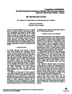
Fig. 1. MEMS loudspeaker cross-section (two magnet structure). Materials: Silicon (grey), silicon oxide (blue), copper (pink), neodymium iron boron magnet (red).
fidelity acoustic quality and the choice was made to look for scientific and technological innovation for each critical element. So, as the efficiency is inversely proportional to the mass, the moving part must be as light as possible. And the emissive surface must be very rigid to avoid vibration modes in the bandwidth and ensure a high acoustical quality. Therefore, the emissive membrane is a plane circular face made in silicon [3]–[5]. A good compromise between rigidity and lightness was met by structuring the back face of the emissive membrane with stiffening ribs [6]. The corresponding study and modal analysis was carried out with finite elements calculation tools. For example, a 7.5 mm radius silicon membrane with a minimum thickness of 20 m and structured with 14 stiffening ribs is a good solution. Moreover, the membrane suspension consists in a set of low stiffness silicon beams. Indeed, the monocrystaline silicon is a material which is insensitive to the mechanical fatigue. It is currently used in MEMS devices, but it is particularly adapted to this special case, as the membrane displacements are far larger than is the usual MEMS: a few hundred micrometers instead of a few micrometers. Furthermore, the coil is a planar copper micro-coil electroplated on the membrane. It was designed in order to be located in the space where the magnetic field is high, so close to the circular membrane edges, and to have the
0018-9464/$31.00 © 2012 IEEE
LEMARQUAND et al.: ELECTRODYNAMIC MEMS: APPLICATION TO MOBILE PHONE LOUDSPEAKERS
required electrical characteristics. So, the coil is rather thick (30 m) and required the development of a special process to deposit it [7]. The electrical supply of the moving coil is achieved thanks to tracks deposited on the suspension beams. Moreover, as the coil weight contributes to the total weight of the moving part, it has to be minimized. Calculations show that the optimum is met when the silicon mass equals the copper one. However, it is technically difficult to deposit thick copper tracks and though the new process developed and the remarkable thickness obtained, the copper mass remains smaller than the silicon one in the realized prototypes. As a consequence of this dimensioning, the moving part has a piston movement and its first normal mode is a drum mode at a frequency rather high in the bandwidth. The static part of the motor is constituted by ring permanent magnets only, which are bonded on the substrate. Their inner radius is chosen to encircle the whole moving part totally. It has to be noted that what is described here is the feasibility of MEMS electrodynamic loudspeakers and the trends and important parameters to do their dimensioning and not a final and fine optimization of the device. III. MOTOR STUDY As said, the motor is designed to achieve a high electroacoustic conversion efficiency and a high fidelity acoustic quality. The transduction efficiency is expressed as follows: (1) where is the air density, the sound celerity in air, the radial induction applied on the coil, the moving face radius, the copper density, the copper electrical resistivity, the copper mass, and the moving part mass. The efficiency is the parameter which would be optimized at the final conception and dimensioning stage. Nevertheless, for the present feasability purpose, (1) shows that the magnetic flux density created by the magnet assembly must be the highest possible. Furthermore, the high acoustical fidelity corresponds to a linear behavior of the transducer. Numerous studies show that the sources of nonlinearities lie in the suspension behavior, in the membrane vibration eigenmodes, in the motor iron [8]–[12]. Both first sources have already been considered and the structure designed accordingly. As to the motor, the suppression of the iron makes the eddy currents and the reluctance force disappear. Moreover, the coil inductance in such structures is very low and above the resonance frequency the impedance is resistive and constant. This enhances the linearity of the behavior with regard to the frequency. Besides, the transduction quality is also better when the coil moves in a uniform radial magnetic field all over its displacement range [13]–[15]. So, several electrodynamic motor structures are considered and studied. The criteria of comparison are the intensity of the magnetic flux density and its uniformity along the displacement range. A. Axially Polarized Ring Magnets The simplest structure consists in a single axially polarized ring magnet surrounding the moving part (Fig. 2). This structure is characterized by the calculation of the mean value of the radial component of the magnetic field created by the magnet all
3685
Fig. 2. Loudspeaker geometry (single magnet structure). Coil: Light grey. Silicon substrate: Dark grey. Magnet: White.
Fig. 3. Radial field mean value created by an axially polarized ring mm, mm, T) versus the coil position magnet ( [mm] for several ring axial heights, and mm.
over the space where the coil is located. This corresponds to the annular region between mm and mm, which are the inner and outer coil radii. Indeed, as the coil is small, each turn of the spiral can be considered as a circle. Furthermore, the calculations are carried out with exact analytical formulations established by using the coulombian model of the permanent magnet [16], [17]. This analytical model enables fast calculations and pre-optimization, but it does not take into account the actual relative magnetic permeability of the magnets, nor the Eddy current phenomena. Of course, the airgap between the coil and the magnet must be as small as possible. Nevertheless, it can not be smaller than 0.5 mm to warrant a good mechanical functioning. Fig. 3 shows how the radial field mean value varies for several values of the magnet height, (dimension along the z axis), and versus the coil position along the z axis. The upper face of the ring magnet is in the plane and the coil is considered to be in the same plane. For each magnet height, meets a maximum that occurs for a coil position along the z axis depending on the magnet height. This special position should be chosen as the coil rest position. This means that a spacer of the corresponding thickness should be added between the magnet upper face and the plane of the coil. Moreover, increases with the magnet height, but not in a linear way. So, compromises have to be made, between a high field mean value and an acceptable magnet height and volume for the application, with regard to cost and packaging constraints. Thus, the ring optimal height is between 2 and 3 mm. The same kind of study is done for the ring radial length, . Fig. 4 shows that a 2 mm long ring magnet would be a good compromise. Indeed, increases nonlinearly with the magnet radial length. So, smaller magnets do not create a strong enough field, while longer ones lead to a large magnet volume. Then, a structure with two stacked axially polarized ring magnets, 1.5 mm high, with opposite polarizations is studied. The mean radial magnetic field created is compared to the one created in a single magnet structure, with a 3 mm high magnet. So, both structures have the same magnet volume. As a result, the
3686
IEEE TRANSACTIONS ON MAGNETICS, VOL. 48, NO. 11, NOVEMBER 2012
Fig. 4. Radial field mean value created by an axially polarized ring mm, mm, T) versus the coil posimagnet ( mm, mm. tion [mm] for several ring radial lengthes,
Fig. 5. Radial field mean value created by two axially (light grey) or radially (dark grey) polarized ring magnets versus the coil position [mm]. mm, mm, The magnets have the same dimensions: T, mm, mm.
calculations show that magnetic field created in the “double” structure is symmetrical with regard to the rest position, which is not the case in the “single” structure. Moreover, it is 12% higher in the double structure. B. Radially Polarized Ring Magnets Motor structures with radially polarized ring magnets are also considered. They are constituted either by one ring magnet or by two stacked rings of same radial polarization. The mean value of the radial magnetic field is calculated [18]. Fig. 5 compares the values obtained in the “double” structures: axially or radially polarized magnets. The axially polarized magnets create a radial field which is more uniform than the radially polarized ones for displacements of mm. However, for the intended coil displacements, which are closer to mm, both structures create approximately the same field. When comparing the force factor, Bl, in each of the four structures versus the coil position along the z axis, the “double” axial structure is the best with a value of 0.35 Tm (N/A) which does not depend on the coil position. As axially polarized magnets are more easily manufactured than radially polarized ones, the preference goes to them. Then, “double” structures are more complicated to assemble than “single ” ones, but they have better performances. From the industrialization point of view, choices have to be done. As for the prototypes, both structures were realized and characterized. IV. PROTOTYPES So, several prototypes were built, with either one or two axially polarized ring magnets. The chosen permanent magnet material is neodymium–iron–boron and the grade is N52, which is the strongest grade easily available on the market, with a residual induction around 1.45T and a maximum energy product
Fig. 6. Loudspeaker prototype with one axially polarized ring magnet. Left: emissive surface and ring magnet. Right: backside with 14 stiffening ribs.
Fig. 7. Acoustic intensity at 10 cm (dB SPL) versus excitation frequency (Hz) for an axially polarized single magnet motor.
around 410 kJ/m . The ring height is 3 mm, the radii are 8 and 11 mm. The deep reactive-ion etched silicon membrane has a 7.5 mm radius, a minimum thickness of 20 m. The first membranes realized were structured with 40 stiffening ribs, the further ones with only 14 ribs (Fig. 6 right), thus decreasing the mass from 32 to 24 mg. The 35 turn micro-coil is 30 mm thick (Fig. 6 left). To comply with the new requirements of the smart phone manufacturers and the mobile phone network operators for high fidelity mobile audio systems, the aim has been set to an acoustic intensity of 70 dB SPL at 10 cm in a bandwidth from 300 Hz to 12 kHz. Then, the peak to peak displacement corresponding to the 300 Hz low frequency is 600 m. This is a very large range, which goes far beyond the usual MEMS ones. Moreover, fatigue tests of the suspension were carried out. The moving part and the suspension beams were submitted to more than one billion cycles at 650 Hz (more than 200 days) with 1 mm maximum displacement without breaking. The prototypes were characterized and tested. The typical measured electrical values are around 13 for the resistance and 10 H for the inductance. As a remark, the measured impedance is a constant resistance in the whole bandwidth. Fig. 7 shows the response when the MEMS is excited with a 1 voltage and the acoustic pressure is measured at a 10 cm distance. The theoretical increase of 12 dB per decade below the low cut off frequency is clearly observed below 400 Hz. The response is then a constant from 300 Hz to 100 kHz. Indeed, the first vibration mode of the membrane, the drum mode, is to be seen at 10 kHz. For higher frequencies, the level seems to increase, but this is not exact, as the loudspeaker is then no longer omnidirectional and the measurements are made directly in front of the device. The second vibration mode is seen for a 80 kHz frequency. So, the loudspeaker bandwidth proves very high and far higher than first required. Moreover, the 70 dB SPL at 10 cm acoustic intensity is obtained for an electric power of 75 mW. This corresponds to
LEMARQUAND et al.: ELECTRODYNAMIC MEMS: APPLICATION TO MOBILE PHONE LOUDSPEAKERS
3687
V. CONCLUSION
Fig. 8. Acoustic intensity at 10 cm (dB SPL) of the output frequency spectrum Hz and Hz for an axially for a two tone excitation: polarized single magnet motor.
Thus, this paper presents an electrodynamic MEMS loudspeaker for mobile phone applications which has rather unparalleled characteristics. Indeed, to reach high performances such as high acoustic fidelity and efficiency, the whole structure (ironless motor analytically optimized, thick electroplated copper coil, rigid silicon emissive surface) is original. Several electrodynamic motor structures are considered and studied: the best among them seems a motor with two stacked axially polarized ring magnets. Moreover, the moving part has displacements far larger than in already existing MEMS (600 m). Eventually, the 70 dB SPL bandwidth reaches up to 100 kHz on the built and characterized prototypes, whose behavior is particularly linear. REFERENCES
Fig. 9. Acoustic intensity at 10 cm (dB SPL) of the output frequency spectrum Hz and Hz for an axially for a two tone excitation: polarized single magnet motor.
82 dB SPL for 1 W at 10 cm. Furthermore, the acoustic quality of a device is characterized by the harmonic and intermodulation content of its output frequency spectrum when it is excited by a two tone stimulus, f1 and f2. It has to be noted that the intermodulation frequencies are the most bothering defects from the acoustic quality point of view. For Hz and Hz, three harmonics of each fundamental appear, but their highest level is more than 30 dB below the fundamental levels. The intermodulation frequencies and are observed with dB levels (Fig. 8). This case is one of the worst possible, as the low fundamental frequency, 400 Hz, is close to one of the system resonance frequency. When Hz and Hz, no harmonic content at all can be measured (Fig. 9). Moreover, only the intermodulation frequencies are observed with dB levels. These measurements show that this MEMS loudspeaker has a very linear behavior and so, a rather high acoustic quality.
[1] M. Berkouk et al., “Analytical calculation of ironless loudspeaker motors,” IEEE Trans. Magn., vol. 37, no. 2, pp. 1011–1014, Feb. 2001. [2] G. Lemarquand, “Ironless loudspeakers,” IEEE Trans. Magn., vol. 43, no. 8, pp. 3371–3374, Aug. 2007. [3] M. C. Cheng et al., “A silicon microspeaker for hearing instruments,” J. Micromechan. Microeng., vol. 14, pp. 859–866, 2004. [4] P. Rangsten et al., “Electrostatically excited diaphragm driven as a loudspeaker,” Sensors Actuat., vol. A 52, pp. 211–215, 1996. [5] S. C. Ko et al., “Micromachined piezoelectric membrane acoustic device,” Sensors Actuat., vol. A 103, pp. 130–134, 2003. [6] I. Shahosseini et al., “Towards high fidelity high efficiency MEMS microspeakers,” in IEEE Sensors Conf., 2010, pp. 2426–2430. [7] M. Woytasik et al., “Copper planar microcoils applied to magnetic actuation,” Microyst. Technol., vol. 14, no. 7, pp. 951–956, 2008. [8] W. Klippel, “Loudspeaker nonlinearities—Cause, parameters, symptoms,” J. Audio Eng. Soc., vol. 54, pp. 907–939, 2006. [9] R. H. Small, Loudspeaker Large-Signal Limitations, AES Australian Regional Convention, no. 2102, 1984. [10] J. Vanderkooy, “A model of loudspeaker driver impedance incorporating eddy currents in the pole structure,” J. Audio Eng. Soc., vol. 37, pp. 119–128, 1989. [11] A. Dobrucki, “Nontypical effects in an electrodynamic loudspeaker with a nonhomogeneous magnetic field in the air gap and nonlinear suspension,” J. Audio Eng. Soc., vol. 42, pp. 565–576, 1994. [12] R. Ravaud et al., “Ranking of the nonlinearities of electrodynamic loudspeaker,” Arch.. Acoust., vol. 35, no. 1, pp. 49–66, 2010. [13] B. Merit et al., “In pursuit of increasingly linear loudspeaker motors,” IEEE Trans. Mag., vol. 45, no. 6, pp. 2867–2870, Jun. 2009. [14] M. Remy et al., “Ironless and leakage free voice-coil motor made of bonded magnets,” IEEE Trans. Magn., vol. 44, no. 11, pp. 4289–4292, Nov. 2008. [15] B. Merit et al., “Performances and design of ironless loudspeaker motor structures.,” J. Appl. Acoust., vol. 71, no. 6, pp. 546–555, 2010. [16] R. Ravaud et al., “Analytical calculation of the magnetic field created by permanent-magnet rings,” IEEE Trans. Magn., vol. 44, no. 8, pp. 1982–1989, Aug. 2008. [17] S. I. Babic and C. Akyel, “Improvement in the analytical calculation of the magnetic field produced by permanent magnet rings,” Prog. Electromagn. Res. C, vol. 5, pp. 71–82, 2008. [18] R. Ravaud et al., “Magnetic field created by tile permanent magnets,” IEEE Trans. Magn., vol. 45, no. 7, pp. 2920–2926, Jul. 2009.