TELKOMNIKA, Vol. 11, No. 7, July 2013, pp. 3699 ~ 3703 e-ISSN: 2087-278X
3699
Electromagnetic Environment and Target Simulator for Radar Test Jurong Hu*, Xuning Zhu, Long Chen Dept. of Electronic and Information Engineering, University of HoHai, Nanjing, Jiangsu Province, China *Corresponding author, e-mail:
[email protected]
Abstract This paper describes the design of a general purpose electromagnetic environment and target simulator which is used to test radar and its components. The simulator was a hardware system controlled by computer software which generated echoes of targets, clutter and jamming for radar electromagnetic environment scenario simulation. It responded to the subject radar’s antenna scan by producing composite echoes in real time. Computer programs were used to management the simulation process and allowed various combinations of electromagnetic environment. Parallel signal generator was exploited to increase the execution speed and achieve real-time performance. Since the simulator could produce video frequency and intermediate frequency echo separately it was used for the test of most components of radar. The capability to accommodate dynamic scenarios of long duration in real time for detailed tracking studies distinguished the simulator from other pulse-by-pulse simulators that had been previously reported. Keywords: simulator, target model, clutter model, real-time simulation, radar test Copyright © 2013 Universitas Ahmad Dahlan. All rights reserved.
1. Introduction In order to evaluate performance of different radar such as signal processing as well as target detecting and tracking, an extensive series of field tests must be conducted. To cover the various conditions of foliage, clutter, weather and terrain characteristics, several test sites must be chosen and even then, the test results apply only to specific and limited set of conditions. Therefore, field tests lack generality and repeatability and it is difficult to estimate the ability of radar under electronic counter measure (ECM). Furthermore, the effect of the electromagnetic environment and ECM on radar performance usually needs to be observed over a relatively long period of time, while radar attempts to execute its normal mode switching sequence to acquire and track detected targets [1]. A high-fidelity multifunction simulator which simulates echoes of the electromagnetic environment and targets can be used to test radar with high accuracy and repeatability [2-5]. The electromagnetic environment and target simulator is designed to test radar in the L, C-, X- and S- band separately. It supports long scenario durations during the simulation run which is particularly important for studying the effects of electromagnetic environment on radar tracking performance. The simulation of electromagnetic environment includes clutter echoes of ground, sea and weather separately along with ECM echoes such as range gate pull-off and velocity gate pull-off. Through the simulating software the simulator can be set up a pattern of parameters for electromagnetic environment scenario. In a simulating run, the simulator interacts with the subject radar by sensing the antenna scan angle and responding in real time with the correct composite backscatter from the electromagnetic environment and target. It is a hardware system controlled by computer and approximates the output of a radar receiver in video frequency (VF) and intermediate frequency (IF) on a pulse-by-pulse basis for arbitrarily long scenario durations. Detailed simulation models and algorithms about target and clutter to simulate large scale radar scenarios are presented in part 2. An overall description and system concepts of the simulator is presented in part 3. A functional diagram shows the relationship between major portions of the simulator. The radar signal generator, management of database and simulation preparing software are discussed too. Some simulation results about the clutter and simulator are presented to demonstrate how the simulator can be used to gain insights into the subject radar performance. Also the conclusion about the simulator is described finally. Received January 28, 2013; Revised April 10, 2013; Accepted April 20, 2013
e-ISSN: 2087-278X
TELKOMNIKA
3700
2. Simulation Model and Algorithm The simulator is developed for the research and development of radar by producing synthetic backscatter echoes which simulate the external electromagnetic world of radar. The synthetic echo generation depends on the model of clutter and ECM as well as simulation algorithm [6-10]. The simulation scenario is assumed to be an annular shaped region, which represents the portion of the battlefield visible to the radar. In Fig. 1, the region is subdivided into concentric rings at constant range from the subject radar and radial columns at constant azimuth with reference to the subject radar. The simulated antenna beam consists of a contiguous subset of m of these azimuth columns. The intersection of range rings and azimuth columns defines a subdivision of the scenario into four-sided cells, which will hereafter be called simulation cells. The concept of the simulation cell is useful for the simulator in defining the scenario. The simulation algorithm in this simulator includes target and clutter models. 2.1. Target Simulation Model The target transmits are assumed to be omni-directional for the purposes of the simulation and Swerling models are used for the radar cross section of targets [1]. During scenario definition, parameters of target consist of target’s movement definition and a schedule of events. The target signal strength is apportioned between two adjacent range rings. Assume that the target’s signal strength is s and the target is located at the center of range ring rm and rm1 . Let d0 and d1 denote the respective distances between the target and the centers of range rings rm and rm1 . Then the backscatter from the target is represented as d1s / ( d 0 d1 ) and d0 s / (d0 d1 ) for range ring rm and rm1 respectively. This technique eliminates an abrupt discontinuity as the target crosses the boundary between range rings. 2.2. Clutter Model and Simulation Algorithm In the clutter simulation model, a smooth spherical earth surface is divided into simulation cells over a desired region as shown in Figure 1 and all the samples at the same range are added together (azimuth integration). The result is a range profile -one value for each range ring .The sample values of range and azimuth are automatically consistent with the achievable range and Doppler resolution of the subject radar. Studies have investigated the statistical nature of ground clutter and sea clutter observed near grazing incidence for a heterogeneous scene [1]. The clutter scenario of various types under different conditions provides the information required for the simulation algorithm. The simulation algorithm converts random numbers into complex scattering matrices, which are statistically appropriate for the clutter being modeled with given probability distribution function (PDF) and power spectral density (PSD). A zero-memory nonlinearities method is employed to complete this conversion. As shown in Figure 2, clutter is synthesized by applying zero-mean unit-variance complex Gaussian random numbers x ( t ) with PSD of x ( ) and PDF of f ( x ) to the filter h1 (t ) at first. Through linear transform the output PDF of
f ( p)
. Then
p (t )
p (t )
is Gaussian random variable with PSD of p ( ) and
is applied to filter h2 (t ) to do nonlinear transform and the output
y (t )
will be random numbers with given PDF of f ( y ) and PSD of y ( ) . The output from the filters has spectra and amplitude distributions that are controllable by functions of the filter parameters. The computed samples representing returns from simulation cells at the same range are coherently summed and placed in the appropriate range gates within each pulse repetition interval.
3. Concepts and Description of the Simulator The simulator is developed for the research and development of radar by producing synthetic backscatter echoes which simulate the external electromagnetic world of radar. The synthetic echo generation depends on the model of clutter and ECM as well as simulation algorithm [6-10]. A functional diagram in Figure 3 shows the relationship of major portions of the simulator.
Electromagnetic Environment and Target Simulator for Radar Test (Jurong Hu)
3701
e-ISSN: 2087-278X
z
Simulation cell
x(t)
x
y
m
m+1
p(t)
x ( )
h1() ( ) p
f (x)
f (p)
h2 ()
y(t)
y ( ) f (y)
Figure 2. Block diagram of simulation algorithm for clutter
Figure 1. Sketch map of simulation cells According to the simulation algorithm and model, the simulator generates the output data about clutter and target which are formed into database stored in the work station. During a simulation run, the database is used to produce the simulated scenario accordingly when the radar’s antenna reaches a specified azimuth, which increases the repeatability of the simulator experiments. The work station is responsible for resource management and process monitoring of the simulator. The model simulation computer initiates a simulation run by defining simulation scenario which includes the model parameters of targets, clutter and jamming. The control computer processes the data about scenario information according to the parameters transferred by the radar work parameters interface. The signal generator responds to the antenna's azimuth by generating the VF and IF signals. The output of the radar signal generator for a given coherent processing interval (CPI) represents a coherent summation of the echoes of targets, clutter and jamming by the appropriate models. 3.1. Simulation Preparing Software The simulation preparing software consists of a graphical user interface (GUI) and a radar simulating data generator (RSDG). The GUI contains all the variable declaration sections for the entire model and acts as a framework linking all the processing blocks together. Using this system, new processing blocks can be introduced into the simulator easily. Through GUI, the flexible simulator can control types and parameters of target, clutter and jamming. With the parameters of simulation scenario defined through GUI, RSDG retrieve simulation data from the database on workstation to form into a sub-database and computes the phase and magnitude of echoes from targets, clutter and jamming on a pulse-by-pulse basis according the simulation model. All the scenario information and simulation results are stored on model simulation computer. The RSDP is designed to process the echoes sets according to the radar working parameters and send them to the radar signal generator automatically. Each target, clutter and jamming data set is in the form of I and Q pairs. 3.2. Management of Database Echoes of the clutter are simulated in advance and the simulation data and reference information are then formed into a database for storage, further processing or display. During a simulation run, according the initialization parameters of the subject radar, the corresponding simulation scenario data are read into the control computer and form a sub-database for realtime simulation. The clutter database includes many kinds of terrestrial clutter at incidence angles close to grazing for L-, S- ,C-and X-bands. Besides the simulation data, the clutter database also includes numerous measurements collected by a certain graduate school. 3.3. Radar Signal Generator Radar signal generators produce VF and IF synthesized signals of the simulation scenario. They are mounted in the PCI slots in control computer. To achieve real-time performance, the execution speed of simulator is increased by exploiting three parallel signal processors for the multiple target and electromagnetic environment scenario. Three VF hardware components are used to generate the signal of target, clutter and jamming separately. TELKOMNIKA Vol. 11, No. 7, July 2013 : 3699 – 3703
e-ISSN: 2087-278X
TELKOMNIKA
3702
The flow of data between these components is illustrated in Figure 4. In a simulation run, the control computer retrieves data from model simulation computer according to antenna bore sight direction and wavelength of radar received from the subject radar. The signal processor calculates the bearings of the targets, clutter and jamming relative to the transmit antenna’s bore sight and applies the antenna gain in that direction to each pulse record. The generator is triggered by the time impulse from subject radar and generates the VF signal incorporating the subject radar's transmitter modulations. Then the signals are synthesized into one which is sent to the IF hardware to simulate the transmitter modulation of the subject radar. All the data are retrieved at the pulse repetition frequency (PRF) and several repetitions of the same data are used in one CPI.
Figure 4. Data flow of signal generator
Figure 3. Functional diagram of the simulator
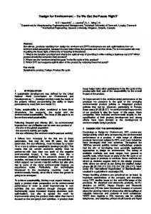
4. Simulation Results The simulator is developed to address many kinds of radars. To illustrate the operation of the simulator and its ancillary programs, a number of the simulation runs are performed for scenarios that involve the major categories supported by the simulator. Typical application studies where severe near-launch tracking problems for the subject radar have been done. Those studies demonstrate the capability of the simulator for a particular situation. Figure 5 and 6 show the simulation results of clutter and Key performance characteristics of this simulator are presented in Table 1. The simulator concept and hardware implementation possess the flexibility to permit realistic generation of synthetic radar backscatter for a variety of radars.
probability distribution function
1
power spectral density
0 simulation result theoretical value
0.9
simulation result theoretical value -5
0.8
-10
0.7 Spectrumamplitude(dB)
-15
pdf
0.6
0.5
0.4
-20
-25
-30 0.3 -35
0.2
-40
0.1
0
0
5
10
15
20 N
25
30
35
-45
0
100
200
300
400
500 600 frequency
700
800
900
1000
Figure 5. Log-norm PDF and Guassian PSD clutter simlation result
Electromagnetic Environment and Target Simulator for Radar Test (Jurong Hu)
e-ISSN: 2087-278X
3703
probability distribution function
1
power spectral density
0 simulation result theoretical value
0.9
simulation result theoretical value -5
0.8
-10
0.7 Spectrumamplitude(dB)
-15
pdf
0.6
0.5
0.4
-20
-25
-30 0.3 -35
0.2
-40
0.1
0
0
5
10
15
20
25
30
35
-45
0
100
200
300
N
400
500 600 frequency
700
800
900
1000
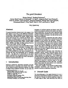
Figure 6. Weibull PDF and Guassian PSD clutter simlation result Table 1. Performance characteristics of simulator PRF pulse width IF(user choose) Maximum number of target’s flights Bandwidth response time in real-time simulation phase noise of IF signal spurious spectrum range resolution
300Hz---20KHz 1us---500us 30MHz、32MHz、70MHz 100 ≤10MHz ≧250μs -105/1Hz/@1KHz 70dBC 1.5m
5. Simulation Results This paper presents a simulator developed to test many kinds of radars. The simulator draws on simulation models and algorithms to create radar electromagnetic environment scenario. The simulator is based on a highly modular structure which allows new function blocks to be included easily. The results presented in this paper illustrate the versatility of the simulator in modeling target and clutter. The simulator is instrumental in reducing the time required for radar system checkout and verification of processing algorithms. Future applications should also help prove the viability of simulator as an alternative or adjunct to field test programs. Therefore this simulator will continue to evolve as a tool, with increased emphasis on its use as a simulation test bed for new radar.
References [1] MI Skolnik. Radar Handbook. McGraw-Hill. 1990. [2] Hai Si, Wen Zhang, Zhan Liu, Zhao-Du Wei, He and Li, Jingliang. Design on radar signal simulator of automotive ACC. Proceedings of the 2009 IEEE International Conference on Automation and Logistics, ICAL. 2009: 1450-1453. [3] Wakabayashi, Nobukazu Makino, Hidenari, Mori, Kenji; Shiotani and Shigeaki: Development of radar simulator software using AIS data for ship data. OCEANS'10 IEEE Sydney. [4] Zhao Zhiyong, Chang Wenge, Li Xiangyang and Yan Feifei. Design and realization of wideband radar signal simulator. Proceedings of 2011 IEEE CIE International Conference on Radar, RADAR 2011. 2011; 2: 1280-1283. [5] Flores-Tapia Daniel, Thomas Gabriel, Sabouni Abas, Noghanian Sima and Pistorius Stephen. Breast tumor microwave simulator based on a radar signal model. Sixth IEEE International Symposium on Signal Processing and Information Technology, ISSPIT. 2007; 17-22. [6] Liu JinHui, Liao Gui-Sheng and Li Ming: Modeling and analysis of ground clutter for long baseline bistatic airborne radar. Systems Engineering and Electronics. 2011; 33(3): 523-527. [7] Ward KD and Watts S. Use of sea clutter models in radar design and development. IET Radar, Sonar and Navigation. 2010; 4(2): 146-157. [8] Luo Xiaobo, Liu Zheng, Lu Zaiqi and Fu Qiang. Modeling and simulation of sea clutter for missileborne radar. Proceedings of SPIE - The International Society for Optical Engineering. 2011; 8191. [9] Kiriazi, John E, Boric-Lubecke, Olga; Lubecke and Victor M. Considerations in measuring vital signs cross section with doppler radar. 2011 IEEE Radio and Wireless Symposium, RWS. 2011; 426-429. [10] Krolik Jeffrey, Mecca Vito, Kazanci Oguz and Bilik Igal. Multipath spread-Doppler clutter mitigation for over-the-horizon radar. 2008 IEEE Radar Conference.
TELKOMNIKA Vol. 11, No. 7, July 2013 : 3699 – 3703