IEEE TRANSACTIONS ON MAGNETICS, VOL. 46, NO. 2, FEBRUARY 2010
563
Electromagnetic Modeling of Ethernet Transformers David Bowen1 , Isaak Mayergoyz1 , and Charles Krafft2 ECE Department, UMIACS, and the Center for Applied Electromagnetics, University of Maryland, College Park, MD 20742 USA Laboratory for Physical Sciences, College Park, MD 20740 USA The unique features of Ethernet transformers are reviewed, and novel testing techniques for identification of lumped parameters of equivalent circuits are presented. To account for the distributed nature of the cross-winding and intrawinding capacitances, novel distributed models for electromagnetic analysis of Ethernet transformers are presented. Index Terms—Common-mode, differential-mode, Ethernet transformer, open-circuit test, short-circuit test.
I. INTRODUCTION IDEBAND ferrite core Ethernet transformers are widely used for interfacing communication networks with computers. The main functions of these transformers are to suppress common-mode (noise) signals and transmit with minimal distortions differential-mode (information carrier) signals in the high frequency range of 0.1 MHz–1 GHz. To achieve these functions, the design of Ethernet transformers appreciably deviates from the design of conventional power transformers [1]–[3]. In the conventional transformers, the primary and secondary windings have different numbers of turns to step up (or step down) the voltage or for impedance matching purposes. These windings are separately wound and displaced with respect to one another. In wideband Ethernet transformers, on the other hand, the primary and secondary windings usually have the same number of turns, and they are wound together (in bifilar manner) around ferrite cores. This winding arrangement is used on purpose in order to minimize leakage inductances of the primary and secondary windings. This is essential to make the performance of Ethernet transformers closely replicate the performance of an ideal transformer, which has flat transfer characteristics for differential-mode signals. However, the close proximity of the primary and secondary windings results in appreciable cross-winding capacitance, which is usually beneficial to the bandwidth of differential-mode transfer characteristics at very high frequencies. At the same time, this cross-winding capacitance serves as a channel for common-mode (noise) signals. To suppress this channel and filter out common-mode signals, the midpoints of the primary and secondary windings are grounded. This midpoint grounding results in low impedances of the primary and secondary windings to common-mode signals. It is clear from the above discussion that the design of Ethernet transformers is tailored to achieve two primary goals: flatness of differential-mode transfer characteristics in the desired frequency range and discrimination of common-mode
W
Manuscript received June 19, 2009; revised September 07, 2009; accepted September 17, 2009. Current version published January 20, 2010. Corresponding author: D. Bowen (e-mail:
[email protected]). Color versions of one or more of the figures in this paper are available online at http://ieeexplore.ieee.org. Digital Object Identifier 10.1109/TMAG.2009.2033203
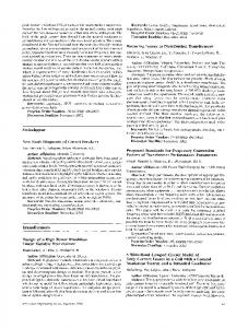
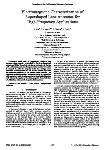
Fig. 1. 1-Gb/s Ethernet link measured signal spectrum. (a) Common-mode; (b) Differential-mode.
and differential-mode signals. Fig. 1 presents spectra of common-mode and differential-mode signals measured for unshielded twisted pair (UTP) cables for a 1-Gb/s network interface by using magnetic clamp current probes. These measurements have been performed in the 5 Hz–1 GHz range. The UTP cable was connected to two PCs exchanging data in a laboratory environment with the usual level of background electromagnetic interference. The figure reveals that the common-mode signals are most appreciable in the low-frequency region (below 0.1 MHz), while the differential-mode signals are concentrated in the 0.1 MHz–1 GHz frequency range. It is in this frequency range that the differential-mode transfer characteristic of Ethernet transformers must be flat in order to avoid the distortion of transmitted information. This paper is concerned with the characterization, testing, and modeling of Ethernet transformers. First, the lumped parameter equivalent circuit of Ethernet transformers for differential-mode signals is discussed, and novel testing techniques for empirical identifications of parameters of this equivalent circuit are presented. The conventional testing techniques (such as open- and short-circuit tests) used for power (low-frequency) transformers are not applicable to Ethernet transformers because winding currents and ac powers are not easily measurable. Special modifications of these techniques that rely only on peak values voltage measurements are advocated in the paper. Since the primary and secondary windings of Ethernet transformers are closely intertwined, the cross-winding and intrawinding capacitances are distributed in nature. In the paper, novel distributed models for Ethernet transformers are presented, and explicit formulas for differential-mode transfer characteristics are derived and numerically illustrated. Finally, the case for an air-core Ethernet transformer is made. These transformers are attractive because
0018-9464/$26.00 © 2010 IEEE
564
IEEE TRANSACTIONS ON MAGNETICS, VOL. 46, NO. 2, FEBRUARY 2010
ferrite cores are problematic due to their high-frequency core losses, frequency degradation of their magnetic permeability, and intrinsic incompatibilities of magnetic and silicon technologies that inhibit miniaturization of Ethernet transformers and their integration with electronic circuits. II. LUMPED PARAMETER EQUIVALENT CIRCUIT OF ETHERNET TRANSFORMERS The primary and secondary terminal voltages of Ethernet transformers have three distinct components: voltage drops due to resistances of primary and secondary windings, voltage drops due to leakage inductances of primary and secondary windings caused by magnetic field lines that partially (or entirely) go through air, and finally, voltages induced in the primary and secondary windings by the time-varying flux in the ferrite core that is formed by magnetic field lines that are entirely confined to the core. By taking into account that primary and secondary windings of Ethernet transformers are practically identical, this can be expressed mathematically as follows:
(1) Here, and are the phasors of the primary and secondary voltages, and are the phasors of the primary and secondary are resistance and leakage reactance of currents, and the windings, respectively, while is the phasor of the voltage induced in each winding by the flux formed by the magnetic field lines entirely confined to the ferrite core. We shall next derive the expression for . By using Ampere’s Law (2) and usual reasoning, we obtain (3) is the where is an average length of the ferrite core and number of turns of each winding. By multiplying formula (3) of the by the complex magnetic permeability ferrite core, by the cross-sectional area of the core and by , we arrive at the expression for the flux linkages of the primary and secondary windings (4)
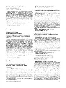
Fig. 2. Transformer equivalent circuit. (a) without capacitances (b) with capacitances.
By substituting formulas (5)–(6) into (1), we arrive at the following form of the coupled-circuit equation: (8) (9) It is apparent that (8)–(9) coincide with the KVL equations for the electric circuit shown in Fig. 2(a). In this sense, this circuit can be construed as an equivalent circuit for Ethernet transformers. At high frequencies, the cross-winding (C) and capacitances are quite pronounced and must intrawinding be taken into account. This leads to the equivalent circuit shown and in Fig. 2(b). As customary in transformer theory, the in Fig. 2 can be replaced by the equivalent resistance and connected in parallel. In this case, and are inductance and by the formulas related to (10) By using formula (7) in (10), the following expressions for and are obtained:
(11)
By using the last formula, we find that (5) where (6)
(7)
Next, we consider the experimental identification of and by using only peak-value voltage measurements. This can be accomplished by using the so-called “quasi-open circuit test” (QOCT) in which the terminals of the secondary windings are open, while the primary winding is connected to a voltage source through two known resistances connected in series. Since and , this test can be represented by a circuit shown in Fig. 3(a). and can be found by We intend to demonstrate that , and using the measurements of peak values of voltages
BOWEN et al.: ELECTROMAGNETIC MODELING OF ETHERNET TRANSFORMERS
Fig. 3. Quasi-open circuit test (QOCT). (a) Circuit model; (b) phasor diagram.
565
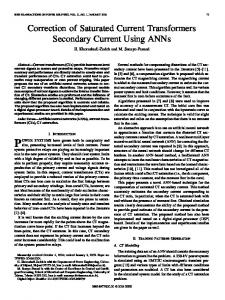
Fig. 4. QOCT extracted core inductance and resistance.
. To this end, consider the phasor diagram (see Fig. 3) for the circuit shown in Fig. 3(a). From this phasor diagram, we derive (12) (13) (14) By solving these equations, we obtain (15)
Fig. 5. Low-frequency quasi-short circuit test (QSCT). (a) Equivalent circuit; (b) phasor diagram.
(16) (17) It is apparent that (18) which leads to the formulas (19) Thus, by using the measured values of , and and and can be formulas (15)–(17) and (19), the values of found at any frequency at which the measurements are percan be neformed provided that intrawinding capacitance glected. By recalling formula (7), we can determine, in this way, and . The experimental rethe dispersion relations and are shown in Fig. 4. It is apparent from Fig. 4 sults for and formulas (8) and (9) that appreciably degrades above assumes its maximum value at about 800 kHz. 1 MHz, while This is consistent with experiments reported in [4]–[6]. Next, we shall discuss the experimental identification of leakage inductance by assuming that the dc winding resistance has been measured and is known. This resistance may change with frequency due to the skin effect. These changes can be easily accounted for by using the analytical expression for the ac resistance in terms of Bessel functions. The experimental identification of leakage inductance can be performed by using
the so-called “quasi-short circuit test” (QSCT). In this test, the terminals of the secondary winding are connected to a known small (approximately equal to ) load resistance . Since the branch, which, load resistance is small, it shunts the consequently, can be neglected. The cross-winding capacitance can be neglected if the test is performed at relatively low frequencies. Thus, we arrive at the electric circuit shown in Fig. 5(a) The corresponding phasor diagram is shown in Fig. 5(b). From this diagram, we find (20) In addition, the following equalities are valid: (21) By using the last two formulas (20) and (21), we derive (22) Thus, by measuring the peak values of voltages and and by using formula (22), we can find the leakage inductance . The experimental results for in the frequency range 3–6 MHz are practically constant and equal to 160 nH. The QSCT can be further modified to determine the cross-winding capacitance . In this modification, the test is performed at sufficiently
566
IEEE TRANSACTIONS ON MAGNETICS, VOL. 46, NO. 2, FEBRUARY 2010
By using the last equation, the cross-winding capacitance can be determined. It turns out that this cross-winding capacitance can be also determined from the observation of resonance in the loop formed by the cross-winding capacitance and leakage inductances [see Fig. 2(b)]. There are two possible scenarios for the manifestation of this resonance. In the first scenario, the impedance due to the is much larger than the secondary intrawinding capacitance - branch and can be neglected. In this impedance of the case, the resonance occurs in the loop formed by the parallel branches connected to the nodes 1 and 2. In the second scenario, branch is much larger than the the impedance of the impedance of the secondary intrawinding capacitance , and the former can be neglected. In this scenario, the resonance occurs in the loop formed by the parallel branches connected to the nodes 1 and 3. It turns out that due to the smallness of the resonance frequencies for these two scenarios are practically the same and given by the formula Fig. 6. High-frequency QSCT for cross-winding capacitance determination. (a) Circuit; (b) phasor diagram.
(26) At the resonance frequencies, the total impedance of parallel branches is purely resistive and, with high accuracy, it is given by the formulas, respectively and
Fig. 7. Transfer characteristic with resonance.
high frequencies, and peak values of voltages and [see Fig. 6(a)]are measured. The phasor diagram corresponding to the circuit shown in Fig. 6(a) is given in Fig. 6(b), where two equal angles are identified. It follows from the above phasor diagram that (23) and (24) By using expressions for , and in terms of and , (24) can be transformed into the following quadratic equation for :
(25)
(27)
For the typical case of sufficiently small and , the resocan be quite large and comnance value of the impedance parable to the impedance of the - branch or the impedance due to . This may result in the dip of the peak value of and, consequently, in the dip of the measured transfer characteristics. This resonance dip may be enhanced by the decrease in due to the decrease in in the frequency range around . The performed calculations have shown that the experimental data is better replicated by the second scenario and that may have the prothe secondary intrawinding capacitance found effect on the transfer characteristics near the resonance frequency. In our experiments, we observe that some Ethernet transformers exhibit strong resonance behavior around 60 MHz (see Fig. 7), which corrupts the pass-band of the transfer characteristic. Similar resonance behavior of transfer characteristics of the Ethernet transformer (see Fig. 7) is predicted by the equivalent circuit shown in Fig. 2(b). This transfer characteristic was pF computed by using the cross-winding capacitance identified through formula (26) and the intrawinding capacipF identified through numerous simulations to tance achieve the matching of the spike and dip in the transfer characteristics near the resonance. There are other ways to directly measure the cross-winding and intrawinding capacitances. For instance, the cross-winding can be measured by using low-frequency tests capacitance illustrated by a circuit shown in Fig. 8(a). The phasor diagram of this test is presented in Fig. 8(b). From this diagram, we find
(26)
BOWEN et al.: ELECTROMAGNETIC MODELING OF ETHERNET TRANSFORMERS
567
This means that magneto-motive force (mmf) is uniformly distributed along a ferrite core, and formula (3) as well as subsequent formulas (6) and (7) are fully justified. Next, by applying KVL to two adjacent infinitesimally small elements of the primary and secondary windings at the y-location, we derive (31) (32) Fig. 8. Schematic for the cross-winding capacitance measurement. (a) Circuit; (b) phasor diagram.
(27) which yields (28)
pF. InThe performed experiments resulted in trawinding capacitance can be determined from the opencircuit test performed for sufficiently high frequencies when completely shunts the - branch. Our impedance due to pF. Care must be preliminary experiments yielded exercised when using circuit models to determine small capacitances due to parasitic effects of the fixtures. For intrawinding capacitance, a measurement with the device absent (calibration data) will reveal parasitic capacitance that will sum with the device capacitance when placed in parallel. The calibration capacitance can then be subtracted from the measured capacitance to find intrawinding capacitance.
Here, is the per-unit length impedance of the primary (or secondary) winding consisting of series connected per-unit length resistance and leakage inductance, which are in parallel with is the the per-unit length intrawinding capacitance , while per-unit length impedance . In other words, the second terms on the right-hand sides of (31) and (32) represent voltages per unit length induced in each winding by the magnetic flux formed by magnetic field lines entirely confined to the ferrite core, while the first terms account for the voltage drops per unit length due to other winding parameters unrelated to the ferrite core. Differential equations (29) and (31)–(32) must be complemented by the boundary conditions at the winding terminals. and are odd For differential-mode signals, voltages functions of measured with respect to midpoints of the windings. This implies that (33) (34) where is the length of the primary (and secondary) winding. The boundary conditions at the terminals of the secondary winding depend on its loading. We shall first compute transfer in the case when the secondary terminals are relation open. In this case, the following boundary condition is valid:
III. ANALYTICAL MODELING OF ETHERNET TRANSFORMERS The lumped parameter equivalent circuit for Ethernet transformers shown in Fig. 2(b) does not take into account the distributed nature of cross-winding capacitances. Distributed models of these transformers can be developed along the lines discussed below. Consider two infinitesimally small adjacent elements of the primary and secondary windings. By applying KCL to these elements, we find
(35) By adding (31) and (32) and taking into account formula (30), we obtain (36) By integrating the last equation and taking into account formula (33), we derive (37)
(29) By subtracting (31) from (32), we find where and are currents through the primary and secondary windings at the location defined by coordinate and are the voltages of infinitesimally small elements of the primary and secondary at the same location, while is the cross-winding capacitance per unit length. The last equation implies that (30)
(38) By differentiating the last equation with respect to and then by using (29), we obtain the following differential equation: (39)
568
IEEE TRANSACTIONS ON MAGNETICS, VOL. 46, NO. 2, FEBRUARY 2010
where (40) The solution of (39) that satisfies (33) is given by the formula (41) By solving (37) and (41) with respect to find
and
, we
(42) (43) By taking into account the boundary condition (34) and the fact , from the last two formulas, we derive that (44) Next, by using the boundary condition (35), we derive the expression for in terms of . Indeed, from (32) and (43), we obtain (45) which yields (46) Now, by using the boundary condition (35), we find (47) By substituting the last formula into (44) and canceling simple transformations. we derive
after
(48)
The last formula enables one to compute the transfer relation as a function of frequency. If it is desirable to investigate how the loading of the secondary winding affects the transfer relation, then the boundary condition (35) must be replaced by the following one: (49) where is the loading impedance. By substituting formulas (43) and (46) into the last equations, after simple algebraic transformations, we derive (50)
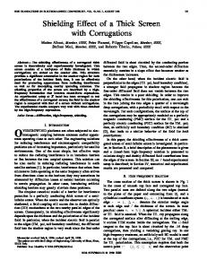
Fig. 9. Simulated distributed model transfer characteristics.
By substituting the last formula into (44) and canceling , after simple algebraic transformations, we obtain the following expression for the transfer function of Ethernet transformers: (51) It is apparent that the last formula is reduced to the expression , i.e., the secondary winding (43) in the case when is not loaded. It is also clear that the last formula, which takes into account the distributed nature of the cross-winding and intrawinding capacitances, can be used for the evaluation of accuracy of the lumped parameter equivalent circuit shown in Fig. 2(b). More importantly, the derived formulas (48) and (51) can be used for the design of air-core Ethernet transformers. These transformers are very attractive as far as their miniaturization and integration with electronic circuits are concerned. The possibility for the design of air-core Ethernet transformers is implied by the fact that the magnetic permeability of ferrite cores substantially and rapidly degrades (see Fig. 4) at frequencies above 1 MHz. This clearly suggests that the differential-mode pass-band of these transformers for frequencies above 50 MHz is a result of the cross-winding capacitance. This crosswinding capacitance coupling between the primary and secondary windings can be enhanced by increasing winding resistances. The latter can be naturally accomplished by using the existing thin-film silicon fabrication technologies extensively used in MEMS designs. For air-core Ethernet transformers with sufficiently large winding resistances, the following inequality will be naturally satisfied: (52) This leads to the following simplifications of the formulas (48) and (51), respectively: (53)
(54)
BOWEN et al.: ELECTROMAGNETIC MODELING OF ETHERNET TRANSFORMERS
For large winding resistances, leakage reactances can be neglected, and can be construed as a parallel connection of and . By taking this into account and by using formula (35) for , the following expressions can be derived: (55) (56) Fig. 9 presents the transfer characteristics for certain values , and . It is clear from Fig. 9 that flat transfer characteristics are achievable in the desired frequency range (0.1 MHz–1 GHz) and . The for certain values of the design parameters distributed model indicates that a nonmagnetically coupled thin-film transformer can have the required behavior to act as an Ethernet transformer. of
569
REFERENCES [1] M. Xu, T. M. Liakopoulos, and C. H. Ahn, “A microfabricated transformer for high-frequency power or signal conversion,” IEEE Trans. Magn., vol. 34, no. 4, pp. 1369–1371, Jul. 1998. [2] H. Kurata, K. Shirakawa, O. Nakazima, and K. Murakami, “Study of thin film micro transformer with high operating frequency and coupling coefficient,” IEEE Trans. Magn., vol. 29, no. 6, pp. 3204–3206, Nov. 1993. [3] D. Bowen, I. Mayergoyz, C. Krafft, D. Kroop, and M. Beyaz, “On design of air-core Ethernet transformers,” J. Appl. Phys., vol. 105, pp. 07A307–, 2009. [4] T. Tsutaoka, T. Kasagi, and K. Hatakeyama, “Magnetic field effect on the complex permeability for a Mn-Zn ferrite and its composite materials,” J. Eur. Ceramic Soc., vol. 19, pp. 1531–1535, 1999. [5] R. Huang, D. Zhang, and K. Tseng, “Determination of dimension-independent magnetic and dielectric properties for Mn-Zn ferrite cores and its EMI applications,” IEEE Trans. Electromagn. Compat., vol. 50, no. 3, pt. 2, pp. 597–602, Aug. 2008. [6] M. I. Rosales, O. Ayala-Valenzuela, and R. Valenzuela, “Microstructure dependence of AC magnetic properties in Mn-Zn ferrites,” IEEE Trans. Magn., vol. 37, no. 4, pt. 1, pp. 2373–2376, Jul. 2001.