VIII International Conference on Computational Plasticity COMPLAS VIII E. Oñate and D. R. J. Owen (Eds) CIMNE, Barcelona, 2005
ELEMENT-SPLITTING FOR SIMULATION OF FRACTURE IN 3D SOLID CONTINUA Peter R. Johnson*, Nikica Petrinic† and Endre Süli* *
Numerical Analysis Group Oxford University Computing Labaratory, University of Oxford, UK e-mail:
[email protected], web page: www.comlab.ox.ac.uk †
Solid Mechanics and Materials Engineering Group Department of Engineering Science, University of Oxford, UK e-mail:
[email protected], web page: www.eng.ox.ac.uk
Key words: Constitutive Modelling, Strain Localisation, Adaptivity, Element Splitting, Fracture, Impact Engineering. Summary. Algorithms for simulation of strain localisation and fracture in 3D solid continua subjected to impact loading are presented. The methodology relies upon the classical continuous Galerkin Finite Element Method for spatial semi-discretisation and the leap-frog central difference scheme for temporal discretisation of the governing partial differential equations. The material behaviour is represented using a rate and temperature dependent hypoelastic-viscoplastic constitutive model with coupled damage and regularised softening. The results presented in this paper are obtained using the constant strain tetrahedral elements. The crack initiation and propagation are modelled using an element splitting method which relies upon quasi-non-local criteria assessed at nodal positions thus allowing for mesh-independent solutions to be achieved. The proposed method uses an efficient local adaptive re-meshing technique in which the elements are divided along the emerging discontinuity using piece-wise planar segments. 1 INTRODUCTION Design of structures threatened by impact-loading requires the ability to predict the emergence of discontinuities at different scales. In the case of design to withstand impact one of the most important design objectives is to improve the ability of given materials to dissipate kinetic energy possessed by colliding solid bodies. The ability of solids to dissipate energy is related to their capacity to deform irreversibly and/or to their capability to fragment and slide along thus created multiple interfaces. Modelling of the material response to impact loading by means of the finite element method has been traditionally performed involving some form of non-linear constitutive model with limiting strain1,7, mesh refinement and element removal technique for representation of fracture. Simulation of strain localisation and fracture in solid materials still represents the challenge as the computational frameworks which rely upon the principles of continuum mechanics are not well suited for problems with inhomogeneous fields within the
Peter R. Johnson, Nikica Petrinic and Endre Süli
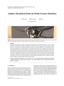
representative volume elements under consideration. Several approaches have been proposed2,3,4,5,6,8 all of which have provided motivation for this work. In this paper, a computationally efficient, numerically consistent, yet pragmatic and industrially relevant methodology is presented which relies upon a combined continuum mechanics and discontinuity analysis virtually unaffected by the underlying finite element discretisation. 2 THE ELEMENT-SPLITTING METHOD The main shortcomings of the element removal approach lie in the crack tip blunting and highly mesh-dependent predictions of crack propagation both in terms of crack orientation and velocity of crack propagation thus resulting in inaccurate overall solutions. In addition, removing elements strongly affects the results as the accurate modelling of crack closure and energy dissipation due to sliding along the created contact surfaces becomes unattainable. In explicit solutions of partial differential equations describing the dynamic equilibrium of solid continua and which rely upon constant strain or reduced-integration finite elements, the extreme values of all fields (e.g. displacement, velocity, strain, stress, etc.) are found at nodal positions of the underlying finite element discretisation. Consequently, it is appropriate to assume that at the locations of these extreme values the discontinuities (cracks) should first emerge. In the proposed methodology, when the employed constitutive model reports that a crack is due to appear, the failed elements are split using piece-wise planar segments while the remaining affected elements are adapted by connecting all newly generated nodes at the crack front (no hanging nodes are allowed at the crack front) and updating element topologies. A non-local technique is used for determining crack orientation at nodal points by averaging the material states from the relevant elements using the node at the point under consideration. In the approach presented in this paper the decision to initiate or propagate a crack is made at a node by checking if all elements intersecting the plane of the prospective crack surface have ceased to resist further to continuing deformation. In the case of a ductile metallic alloy investigated recently it has been shown that the onset and direction of cracks can be predicted reasonably well using a damage mechanics based constitutive model in which the evolution of damage is a proportional to the triaxiality of the material stress state and effective rate of plastic deformation. A characteristic length was used to regularise the evolution of damage and consequent softening as discussed recently9. For the material in question this characteristic length was considered to be the size of the element in the direction of maximum principal rate of plastic deformation. The direction of the crack is also calculated at the node using the information provided by the constitutive model in the adjacent elements as illustrated in Figure 1.
2
Peter R. Johnson, Nikica Petrinic and Endre Süli
Figure 1: Plane of localisation appearing at Gauss point, in left picture. This plane is mapped to node and averaged with other directions from neighbouring elements, on the right hand side.
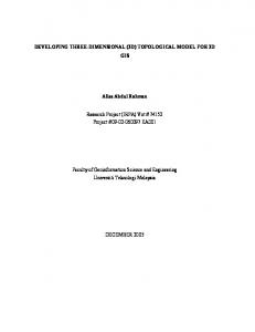
Once the crack plane has been defined the affected elements are split by inserting new nodes where the crack plane intersects element edges. Subsequently, the topology of elements affected by introducing the discontinuity is updated and any newly created outer element faces are added onto the list of contacting entities, as shown in Figure 2. Crack tips created at crack front
Decision is made to start from this node
Node duplicated and element topologies reconnected
Figure 2: Element splitting.
However, the application of the proposed method can easily result in the generation of a large number of small (thin sliver) elements if the crack plane falls near the existing nodes. As a result either the crack plane is “snapped” to that node or the node can be moved to the crack plane aided by a simple local adaptive mapping algorithm. Currently, the snapping parameter is typically a user-defined fraction of the total edge length. It controls the mesh quality at the expense of a small loss of accuracy in the direction of the crack. Other techniques2 are being investigated in which a combination of element based constitutive modelling and discontinuity based cohesive modelling is employed.
3
Peter R. Johnson, Nikica Petrinic and Endre Süli
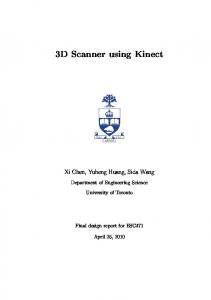
3 DATA MANAGEMENT FOR CRACK INITIATION AND PROPAGATION Following the assumption that a crack will initiate at the node (or propagate from it) when the criteria for crack initiation or propagation are met, the first data management task is to find the intersection between the crack plane and edges of all affected elements. These are the elements sharing the “starting” node as well as all elements which neighbour them. In order to perform these operations efficiently the information on elements sharing edges and faces is kept together with element topologies, and lists of elements using nodes. When the intersections between the crack plane and the element edges are found, the nodes are inserted and the starting node is duplicated (Figure 3). In order to avoid generation of sliver elements nodes are snapped to any existing nodes closet than the user specified tolerance. Subsequently, all affected elements are adapted and hanging nodes are removed by further adapting the affected neighbouring elements. All newly created outer element faces along the crack plane are added onto the list of contacting entities, and finally all the information about elements sharing edges and faces is updated and patched into the existing tables.
Figure 3: Crack initiation at a node, fracture surface in blue, only outer faces of the solid body are shown. Snapping to nodes close to a cut edge is enabled, and is shown here (hence the non-planar appearance of the crack surface.
The stresses and material states of newly created smaller elements have to be interpolated from the results of the larger elements which they replace in the domain by extrapolating them to the nodes, averaging, and then interpolating back to the new Gauss points. This has the effect of healing the elements which have been created from the splitting on the surface of the fracture plane, so that in subsequent time steps they are no longer flagged as failed.
4
Peter R. Johnson, Nikica Petrinic and Endre Süli
Figure 4: Crack propagation from tips of initiated crack. Surface of crack is nearly planar in this example, with snapping to nodes.
In order to extend (or propagate) the cracks further the criteria for crack propagation at nodes along the crack tip front are enhanced. The criteria are modified to take into account the fact that elements along the crack surface behind the crack tip front have been healed. These elements therefore need to be flagged during cracking operation in order to prevent the extensive appearance of secondary cracks. This part of the algorithm is currently under development and needs to be further enhanced in order to allow for better simulation of crack bifurcation and onset of secondary cracks spawning from the fracture surface. 4 CONCLUSIONS An element-splitting methodology for mesh-independent simulation of cracking and fracture of solid continua has been described which allows cracks to initiate and propagate through 3D domains discretised using tetrahedral finite elements. The failure criteria used is node-based thus qualifying as quasi-non-local, and enabling the crack initiation and orientation to be calculated using the averaged damage and averaged directions of the principal rate of plastic deformation within elements using the node. Data management behind the element splitting method is elaborate but essentially straightforward and modular in view of parallel processing. Further work is underway to refine the crack initiation criteria. A combined continuumbased constitutive modelling and discontinuity-based cohesive zone modelling is being investigated such that the mesh can be split and adapted but rather than allowing for the crack to open-up freely a cohesive zone model is employed that describes the behaviour of the discontinuity itself. This method is being compared against a similar method for the simulation of fracture in solid materials based upon the Discontinuous Galerkin Finite Element Method (DGFEM)2 between the two potential fracture surfaces. Further work is also underway to split hexahedral finite elements. It is well known that hexahedral finite elements can more accurately represent the non-linear behaviour of solids and is as such essential that these elements are included into the software.
5
Peter R. Johnson, Nikica Petrinic and Endre Süli
The element splitting method is being extensively used in simulations of laboratory experiments in which the materials are tested at different rates of strain. The method provides a very promising framework for a more elaborate mathematical treatment of fracture by combining the principle of fracture mechanics for brittle materials and error control for the adaptive re-meshing around a crack tip front. ACKNOWLEDGEMENTS The work is supported by a UK EPSRC grant GR/S31761/01. Receipt of this funding is gratefully acknowledged. REFERENCES [1] ABAQUS Theory Manual [2] A. Arranz, N. Petrinic, E. Süli: “Discontinuous Galerkin Finite Element Approximation of Dynamic Fracture”, VIII International Conference on Computational Plasticity COMPLAS VIII, E. Oñate and D. R. J. Owen (Eds), Barcelona, (2005) [3] J. Dolbow, N. Moës and T. Belytschko: “An extended finite element method for modeling crack growth with frictional contact”, Int. J. Num. Meth. Engng, 37, pp. 3323-3341, (1994). [4] R. de Borst, “Numerical aspects of cohesive-zone models”, Engineering Fracture Mechanics, 70, pp. 1743–1757, (2003). [5] C.G. Hwang, P.A. Wawrzynek, A.K. Tayebi and A.R. Ingrafea, “On the Virtual Crack Extension Method for Calculation of the Rates of Energy Release Rate”, Engineering Fracture Mechanics, 59, No. 4, pp. 521542, (1998) [6] E. Kuhl, E. Ramm and K. Willam, “Failure analysis of elasto-plastic material models on different levels of observation”, International Journal of Solids and Structures, 37, 48-50, pp. 7259-7280. (2000) [7] LS-DYNA Theory Manual [8] N. Moës, T. Belytschko, “Extended finite element method for cohesive crack growth”, Engineering Fracture Mechanics, 69, Issue 7, pp. 813-833 (2002). [9] H. Sarsfield, L. Wang, N. Petrinic, “Experimental Investigation of Failure in Ti-6Al-4V”, Third MIT Conference on Computational Fluid and Solid Mechanics, Boston (MA), (2005).
6