USB is used to remote control the test process in compliance with the Universal ... through its own communication channel. ..... components' identification codes.
Embedded test controller for board and system level remote testing Jari Hannu, Tuomas Happonen, Markku Moilanen Optoelectronics and Measurement Techniques Laboratory and OPME Research Group of Infotech Oulu Department of Electrical and Information Engineering, University of Oulu, Finland [jari.hannu, tuomas.happonen, markku.moilanen]@ee.oulu.fi
Abstract—This paper presents an embedded test controller, which can be used for board and system level testing. In addition to controlling IEEE 1149.1/.4 test busses, the test controller can also generate and measure analog test signals. To demonstrate its capabilities, two test cases will be presented. USB is used to remote control the test process in compliance with the Universal Test Communication Standard, which will also be briefly outlined here.
I.
Test communication
Master
Agent
Existing HW interface
Existing HW interface
Protocols
Protocols
Test messages
Test messages
Master SW
Agent embedded SW
INTRODUCTION
achieve good quality and reliable operation over the Towhole life-cycle of an electronic product, requires conducting continuous testing and health monitoring. CostEffective Life-Cycle Testing (LCT) with high fault coverage and advanced diagnostics may be achieved with embedded testing, which also provides test reusability during a product’s life cycle. Embedded test solutions may rely on such designfor-test (DfT) standards as the IEEE 1149.1 and 1149.4, which provide standardized test access to devices and their components. Remote testing enables new possibilities for the testing of electronic devices. For example, maintenance staff will be able to check a device’s condition without transferring the necessary equipment or the device itself from place to place. Remote testing requires both test access to the device and measurement equipment, including test control, which should be embedded in the product. Because embedding full measurement equipment is not a feasible alternative, other test methods must be used. Test access to the device should be established through its own communication channel. This paper introduces an embedded test controller for board and system level testing. In addition to being capable of executing both digital and mixed-signal boundary-scan tests, this controller generates and measures analog test signals and communicates with remote test hosts in conformance with the emerging Universal Test Communication Standard (UTCS) [1]. Although there are solutions for remote embedded testing operations, such as those described in Ref. [2], UTCS aims at being a generally applicable test communication procedure that is independent of the device under test (DUT) and its embedded testing capabilities. The test set-up presented in this paper is the first to demonstrate the operation of UTCS.
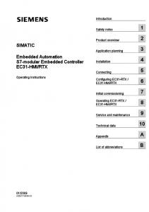
Embedded tests / status information Figure 1. Test communication between a master and an agent
This paper is organized as follows: Section 2 introduces the concept of UTCS, and Section 3 describes the test controller and its components. Section 4 then presents test cases and provides a discussion on the results. The final section of the paper presents our conclusions and outlines future work. II.
UNIVERAL TEST COMMUNICATION STANDARD
Universal Test Communication Standard (UTCS) aims to enable modern electronic devices to perform embedded testing operations both locally and remotely. By utilizing already existing HW interfaces, the test communication procedure facilitates the running of embedded tests as well as retrieval of device status information. The objective of UTCS is to provide a generally applicable communication procedure for the testing of modern electronic devices. It implements test communication between devices using a standardized test message set. Moreover, generally applicable test communication is enabled independently of the HW interface in use. UTCS-based test communication between devices is performed by hierarchical masters and agents. Masters are superior to agents and are used to control them. Agents are embedded SW elements, implemented in electronic devices. Agents are utilized to run embedded test solutions and to
TABLE 1 SUMMARY OF TEST MESSAGES SPECIFIED IN THE UNIVERSAL TEST COMMUNICATION STANDARD
Message
Sender
Service list request
Master
Service list response Run test request Run test response Get result request Get result response Set / Get mode request Mode response Set / Get test parameter request Parameter response Test abort request Test abort response
Agent Master Agent Master Agent
Short description Request for available tests, modes, test parameters and accessible status information Returns the service list or a fail report Request to run an available test with defined attributes Returns the test result based on attributes or a fail report Request for a test result or status information Returns requested information or a fail report
Master
Requests to change or retrieve a used mode
Agent
Returns the requested information or a fail report
Master
Requests to change or retrieve a test parameter
Agent Master Agent
Returns the requested information or a fail report Request for aborting a test operation Returns “operation done” or a fail report
provide device status information or the results of executed tests, based on test messages sent by their masters. From the agents’ point of view, running an embedded test requires the ability to start and execute test operations. Other necessary properties include returning, saving and logging of test results. Figure 1 clarifies the idea. The UTCS test message set consists of request / response type messages sent between masters and agents. Universal applicability dictates that the same messages must be utilizable regardless of the device under test (DUT). This requirement is solved by a device specific service list, which contains available embedded test solutions as well as accessible status information defined by the device manufacturer. As a result, running a test or retrieving status information can be performed DUT independently by generic test messages using identification information defined in the service list. Designed to take advantage of existing protocols, UTCS protocols are preliminary based on Internet Protocol (IP) technology. However, below the internet layer, any suitable network access layer protocol is permitted. At the application layer, several protocols can be exploited, such as the Simple Network Management Protocol (SNMP), which enables requesting status information. In addition, UTCS has similarities with other specifications. For example, parallels can be found with [3], [4] and [5]. However, the idea with UTCS is to use existing solutions to design a novel protocol, comprising a simple, but universally applicable test message set. Using this set allows running any
Figure 2. Test controller block diagram
existing embedded test measure on any DUT and retrieving status information about it. Moreover, these DUT-independent operations can be conducted through any communication link, either locally or remotely, throughout the device’s life-cycle. It is worth mentioning that UTCS is not meant to standardize the embedded test solutions which need to be implemented in devices. It is intended to utilize only such test solutions as are already built into devices. III.
TEST CONTROLLER
The test controller is capable of performing both digital and analog boundary scan tests and diagnosing the measured data. Consisting of three main components, the test controller comprises a microcontroller, analog signal generation unit and analog signal measurement unit. A block diagram of the controller can be seen in Figure 2. Remote control of the test controller is accomplished by LabVIEW via USB using UTCScompliant test messages. Although UTCS is mainly based on IP, this early experiment is conducted using USB. A. Microcontroller The main functions of the microcontroller are: to control the boundary scan bus, to control signal generation and measurement units, to monitor test communication through USB and to diagnose the measured test data. In our tests, the microcontroller was an eight-bit AVR with an USB function (AT90USB1287 [6]). Microcontroller software, as shown in Figure 3, consists of USB control software, test applications and measurement components. The USB control software handles all communication between the test master and agent. A typical test flow is as follows. First, the master runs a test command
Figure 4. State diagram of the test application Figure 3. Microcontroller software components
through USB, launching a test application in the agent. The test application uses measurement components (boundary-scan control and measurement equipment control) to perform the tests and processes the acquired test data. After running the test, the test application sends the result from the agent to the master via USB when needed. While the test is running, the test application sends “Test Running” status to the master. While conducting a test, the application also handles all UTCS control. Figure 4 presents a state diagram of the test application, illustrating the procedure described above. Single test runs are test application functions and may comprise boundary-scan test vectors, analog test-signal requirements, calculation rules and/or expected test results. Shown in Figure 3, the measurement components represent the functions that the test application uses to control tests. Boundary scan control is performed with simple I/O-control, the TMS, TCK, TDI and TRST pins are driven by the software and the TDO pin is used to read test data. Simple I/O is also used to control measurement equipment, while serial control is used in the Serial Peripheral Interface (SPI) and InterIntegrated Circuit (I2C). B. Test Signal Generation and Measurement Commercial components were used to build the test signal generation and measurement units, whose main components can be seen in the block diagram in Figure 2. Based on a programmable waveform generator (AD9833), the test signal generation unit produces sine signals with an accurate frequency. Signal amplitude is determined by an amplifier equipped with a digital potentiometer (DS1804), and the required offset level of the test signal is generated with an 8-bit digital-to-analog converter (MAX5512). The offset voltage and amplified signal are then summed using an amplifier. Finally, the waveform generator and DAC are programmed through an SPI-equivalent port, and the digital potentiometer is programmed through two wire connections. The electrical characteristics of test signal generator are shown in Table 2. The test signal measurement unit consists of two analog switches (TS5A3157), an RMS-to-DC converter (LTC1968) and a 16-bit analog-to-digital converter (ADS1100). The measured test signal is routed through the switches on the following principle: If the test signal is DC, it is routed straight
TABLE 2 ELECTRICAL CHARACTERISTICS OF TEST SIGNAL GENERATOR UNIT fout DC – 500 kHz Voffset (AC)
0–5V
Vpp (AC)
0.1 – 5 V
V (DC)
0–5V
Zout
12 Ω
TABLE 3 ELECTRICAL CHARACTERISTICS OF TEST SIGNAL MEASUREMENT UNIT fin DC – 1 MHz Vin (DC)
0–5V
Vin (AC)
0 – 1.2 V
Zin (DC)
8 MΩ
Zin (AC)
100 MΩ
to the ADC, but if the test signal is AC, it is routed to the ADC via the RMS-to-DC converter. The input of the RMS-to-DC converter is DC-blocked, and its output is low-pass filtered to enable more accurate measurement results to be achieved. The ADC is read through the I2C port, and the switches are driven with a single I/O-pin from the microcontroller. Table 3 shows the electrical characteristics of the test signal measurement unit. C. Test Software for the Master LabVIEW was used to create the test software for the master. To run predefined test cases, the software uses a driver created for the test controller, together with UTCS-accordant messages. In this work, the following messages were applied to control test operations: Service list request and response, run test request and response and get result request and response. To get a service list, the master sends a request message to the agent. In successful operation, the agent returns the requested list in a response message. However, if the requested operation fails, the response message includes an indication of failed operation. The service list may contain available embedded test solutions, modes, test parameters and status information. In this early experiment, the service list includes only available tests. Based on hierarchically listed test solutions, the desired test operation is initiated by a Run Test message. The master sends the message to the agent, requesting it to run a test with a
certain TestID, stated in the service list. Other message attributes are ResultType to determine the format of the test result (“pass/fail” or “raw data”), ResultReturn to determine the return procedure of the test result (“immediately” or “to be stored”) and ResultStore to determine the storage procedure of the result. In successful operation, the response message from the agent returns the test result in a predetermined data format, if requested to do so immediately. If the requested operation is successful, but the test result is requested to be stored, the response message contains a ResultID by which the result can be retrieved with a separate message, when needed. Again, should the operation be unsuccessful, an indication of failed operation is included in the response message. When requesting a test result from the agent, a Get Result message is sent by the master. By sending it, the master requests the agent to return a test result based on its ResultID and ResultType attributes. In successful operation, the requested result is returned, while a failure results in an indication of unsuccessful operation. IV.
TEST CASES
Two test cases were developed to demonstrate the test controller’s capabilities. In the first test case, tests were developed for a boundary scan demo board from Goebel Electronics (Scan Trainer II), for 1149.1 tests. In the second test case, a simple 1149.4 test board was developed to demonstrate the controller’s capabilities for discrete component measurements. A. 1149.1 tests Digital boundary-scan tests were made on a Goebel Electronics Scan Trainer II, which has five components in one scan chain and has the ability to emulate faults on the board. Of the several different tests on the trainer board, we selected Infrastructure and Interconnect tests in order to demonstrate the controller’s capabilities. The boundary-scan control software on the microcontroller contains a set of functions to handle the TAP controller, write data into the instruction or boundary register and read and compare data from the TDO pin. Test vectors are automatically generated by the Goebel Electronics software and stored in the microcontroller’s memory. Infrastructure tests are conducted to verify the test chain’s integrity. In an Infrastructure test, the instruction registers (IR) of the boundary-scan components are connected between the TDI and TDO pins. By default, these registers contain the components’ identification codes. The data from the IRs are shifted out through the boundary-scan chain and compared to the expected result. Also an eight-bit test vector is shifted through the scan chain to verify that there are no errors between the controller and the first boundary-scan component. A dedicated microcontroller software function was developed for infrastructure testing. As input, the infrastructure test function requires the length of the scan chain and the expected test vector and, as output, it gives the test result. In case of error, the function gives the number of the clock cycle when error was recognized.
In general, the procedure for the Interconnect test is as follows. First, an initial state is generated by loading the CAPTURE instruction to the IR of each boundary-scan component, and the initial values of the boundary-scan cells are loaded to the boundary registers (BR). Then, the EXTEST instruction is written to the IR to enable interconnect tests. After this, the state of the boundary cells is captured, read through the TDO pin and compared to the expected result, while next test vector is uploaded to the BR. This procedure is iterated until the final results are read and compared. Two functions were developed for the microcontroller: the first one loads test vectors to the IR, whereas the second one loads the vectors to the BR and compares the results to the expected vectors. As input, the function loading IR data needs the instruction vector and the length of the IR, and it does not produce any output. The function for loading vectors to the BR requires the length of the BR, the input test vector and two vectors for expected results. The first vector contains information about significant bits and the other one their values. Two vectors are used, because they take less memory. As output, the function gives the result of the test, in the same way as the infrastructure test. The test function is repeated consecutively, until the last vector is uploaded and the result is checked. Before each iteration, the result of the previous one is always checked. These interconnect testing functions are so generic that they can be used for any boundary-scan test, provided that the test vectors are changed. Test results can be processed in various ways at a higher software level. In our application, the test results show the underlying reason for each fault as exactly as possible, such as open solder connection on a particular pin. This requires a lot of manual coding. In the 1149.1 tests, the largest problem turned out to be the memory consumption of the test vectors. The test vectors in the interconnection tests alone take about 10% of the microcontroller’s 128 kilobyte memory. Thus, some external memory will be required depending of the size of the boundary-scan chain and the number of different tests. B. 1149.4 tests To demonstrate the test controller’s capability in 1149.4 tests, a simple test circuit, shown in Figure 5, was designed. Adopted from [7], the circuit’s main component is a 1149.4 compatible STA400, manufactured by National Semiconductor. This test circuit allows the measurement of the discrete resistor and capacitor and the component values of the peak detector and the resistive delta network. Customarily, analog test signals are routed through the sense resistor Rs to the analog test pin AT1, from where they are then directed through the AB1 internal bus on the STA400 to the desired pin. The AB2 internal bus is connected to the AT2 pin for voltage measurement. AB2 can be connected to any of the pins on the STA400 for voltage measurements. As the exact value of Rs is known, it is connected between pins A0 and A1, which enables measuring the current flowing to the circuit under test. Measurements on the test controller were similar to the conventional measurement with external measurement
component
TABLE 4 MEASUREMENT RESULTS nominal External err% values Equipment
Test controller
err%
D1 (VF)
0.65
0.65
0
0.61
6.9
R1 (Ω)
66972
66704
0.4
65856
1.67
C1 (nF)
242
213
11.6
383
-58
R2 (Ω)
11769
11761
0.1
11642
1.1
C2 (nF)
10.8
10.3
5
10.4
3.7
R3 (Ω)
503.1
499.7
0.7
381.7
24
R4 (Ω)
502.6
512.5
-2
502.9
-0.1
R5 (Ω)
502.2
511.6
-1.9
460.4
8.3
Figure 5. Simple circuit for 1149.4 tests
equipment. Both single component and block measurements were performed as individual functions. First, the measurement function sets the configuration of the STA400 using the same boundary-scan control functions as the digital boundary-scan tests. After that, a test signal is set in the signal generator unit and the voltage is measured. Then, the next ST400 configuration is set and the voltage measured. After the last measurement, the result is calculated and compared to the expected value. The measurement result constitutes the function’s output. Three measurements were made on each component. First, its nominal values were measured, followed by component measurements using external equipment, including a signal generator, multimeter and boundary-scan controller. Finally, each component was measured using the developed test controller circuitry. Results of these measurements are presented in Table 4. As can be seen from the results, the error is greater with the measurements using presented test controller compared to the measurement using external equipment. It was found that the error is caused by the test measurement unit. The biggest error source in the measurements was probably external offset on the measurement bus which caused measurement at low voltages. This can be seen when the resistances R1 and R2 are measured; the voltage stays quite high during the measurement and the error stays low. Besides the error at low voltages, another problem with the measurements is the time required for ACmeasurements, which is caused of the long rise time of the required filter connected after RMS-to-DC converter. For example, the measurement time of a discrete capacitor can rise up to 1.5 seconds.
into a design called Remote Access Testing Platform, which is under development at the University of Oulu. This platform is intended to emulate real products with such embedded test solutions as BISTs, boundary-scan structures and health monitoring. It will also support UTCS-compliant test communication through Ethernet, Bluetooth or USB. Ethernet access will enable test communication based on IP. The platform’s main test control will be located on its main processor, while the controller presented here will function as a supporting controller. VI.
The authors would like to thank the Technology Development Centre of Finland (TEKES), Nokia, Elektrobit Group, Polar Electro and NetHawk for funding the Remote Access Testing Platform and Basis for Universal Test Communication Standard projects, under which this work was carried out. Warm thanks are also extended to the Foundation of Nokia Corporation for funding. In addition, the authors would like to thank Atmel Corporation for providing samples of the AT90USB. REFERENCES [1]
[2]
[3] [4]
V.
CONCLUSIONS AND FUTURE WORK
An embedded test controller offers the possibility to perform remote test operations on a device throughout its lifecycle. Although the presented test controller supports the 1149.1 and .4 standards, it can also be used to control and execute other embedded test solutions at board or system level. The next step for improving the embedded test controller is to solve the problem of memory requirements for the boundary-scan test vectors and to simplify the test signal measurement unit for more accurate and faster measurements. In the future, the embedded test controller will be implemented
ACKNOWLEDGEMENTS
[5]
[6]
[7]
T. Happonen, T. Koivukangas, and M. Moilanen, “Concept for LifeCycle Testing of Electronic Devices by Means of Universal Test Communication Standard,” Nordic Test Forum 2006, Tuusula, Finland, November 2006. P.Collins, I.Reis, M.Simonen and M. van Houcke, “A Transparent Solution for Providing Remote Wired or Wireless Communication to Board and System Level Boundary-Scan Architectures,” International Test Conference 2005, Austin, USA, November 2005. Open Base Station Architecture Initiative, Reference Point 1 Test Messages, Version 1.0, 21 April, 2005 3rd Generation Partnership Project Telecommunication Management; Test management Integration Reference Point; Requirements, V7.0.0, 2006-09 European Telecommunications Standards Institute; Methods for Testing and Specification; Test synchronization architectural reference, V4.2.4, 2000-09 Atmel Inc., AT90USB1286 – 8 bit AVR Microcontroller with 64/128K Bytes of ISP Flash and USB controller, online data at http://www.atmel.com/dyn/resources/prod_documents/doc7593.pdf, February, 2007. T .Saikkonen, J. Voutilainen, M. Moilanen, “Some Methods to Calculate the Values of Passive Components from the Measurements Made with an 1149.4 Compliant Device”, 2nd IEEE International Board Test Workshop, 2003