ceivers at the optical line termination (OLT) to the maximum sustainable multiplexing gain. This paper, however, focuses on one of the major goals of the project ...
2592
JOURNAL OF LIGHTWAVE TECHNOLOGY, VOL. 22, NO. 11, NOVEMBER 2004
End-to-End QoS Resource Management for an IP-Based DWDM Access Network Brecht Vermeulen, Jeroen Wellen, Member, IEEE, Frank Geilhardt, Erik Weis, Carmen Mas, Bart Dhoedt, Member, IEEE, and Piet Demeester, Senior Member, IEEE
Invited Paper
Abstract—The ever-increasing use of broad-band Internet and complex multimedia applications is pushing fiber closer and closer to the homes. Within the European project IST HARMONICS (Hybrid Access Reconfigurable Multi-wavelength Optical Networks for IP-based Communication Services), an optical access feeder network and resource management framework were developed that tackle this demand for bandwidth and the desire to stimulate the convergence of last-mile access technologies. To cope with the lack of bandwidth in the access and last-mile networks and the different needs of applications and users, the developed management system provides end-to-end quality of service (QoS) while integrating multiple technologies. In this paper, a detailed overview of the end-to-end QoS management framework and novel time slot/wavelength MAC protocol for the optical feeder network is given. End-to-end QoS is based on Differentiated services (DiffServ) at layer 3, various QoS supporting technologies at layer 2, and QoS mappings between both layers. The paper will also focus on the field trial results of the HARMONICS project and give some guidelines for possible problems and solutions in this area. Index Terms—Access networks, common object request broker architecture (CORBA), differentiated services (DiffServ), end-to-end quality-of-service (QoS) management, Internet-protocol-over-wavelength-division multiplexing (IP-over-WDM), medium access control (MAC), optical packet switching (OPS).
I. INTRODUCTION AND MOTIVATION
T
HE growing widespread use of advanced multimedia and interactive real-time applications is setting forth new challenges such as end-to-end quality-of-service (QoS) and broadband Internet access. A variety of emerging advanced network technologies, such as xDSL (digital subscriber line), wireless Hiperlan/2 or IEEE 802.11a,b,g tackle those issues for the lastmile or in-home network. In the broad-band access feeder network which interconnects the Internet core networks and the Manuscript received December 31, 2003; revised August 21, 2004. This work was supported in part by the European Community through the IST research program under the IST-1999-11 719 project HARMONICS. B. Vermeulen, B. Dhoedt, and P. Demeester are with the Ghent University, Interuniversity MicroElectronics Center (IMEC), Department of Information Technology, Gent B-9000, Belgium. J. Wellen is with Bell Laboratories, Advanced Technologies, Lucent Technologies, Hilversum NL-1221 CN, The Netherlands. F. Geilhardt and E. Weis are with T-Nova Systems, Berlin D-10589, Germany. C. Mas is with the Athens Information Technology Center (AIT), Athens 19002, Greece. Digital Object Identifier 10.1109/JLT.2004.837288
last-mile networks (LMNs), wavelength-division multiplexing (WDM) seems ideally suited to provide the necessary bandwidth. The HARMONICS (Hybrid Access Reconfigurable Multiwavelength Optical Networks for IP-based Communication Services) [1] project studied a dense-WDM (DWDM)-based access feeder network carrying IPv4/IPv6 traffic with QoS guarantees. HARMONICS stimulates the convergence of access networks by supporting a variety of LMN technologies. Differentiated services (DiffServ) is used as an end-to-end QoS mechanism at layer 3, supported at layer 2 by a novel wavelength/time slot medium access control (MAC) protocol in the passive optical network (PON) and novel QoS mappings in the various last-mile technologies. To set up and manage end-to-end QoS flows, HARMONICS uses a distributed flow management software architecture. Users or applications who require a prioritized flow send a request, for example, a Resource reSerVation Protocol (RSVP) message, to the management architecture. The network management checks whether the necessary resources are available, negotiates service level agreements (SLAs) with neighboring networks, and makes the necessary configuration changes to support this new flow. Within the project, different scenarios were studied for the optical access feeder ranging from 64 optical node units (ONUs), serving a total of 3200 very-high-bit-rate digital subscriber line (VDSL) subscribers, to 1024 ONUs for fiber-to-the-home/fiber-to-the-building (FTTH/FTTB). The concept allows for migration, where the number of wavelength channels can be increased, while adapting the number of transceivers at the optical line termination (OLT) to the maximum sustainable multiplexing gain. This paper, however, focuses on one of the major goals of the project, namely the support of end-to-end QoS with strict guarantees. Both laboratory trials and a field trial were organized to evaluate the developed solutions in a quantitative and qualitative way. The remainder of this paper is structured as follows: Section II describes the HARMONICS network architecture in detail. Section III discusses how end-to-end QoS is achieved within HARMONICS, while Section IV elaborates on the distributed QoS management software architecture. Finally, Section V presents an overview of the field trial followed by some issues, solutions, and conclusions in Sections VI and VII.
0733-8724/04$20.00 © 2004 IEEE
VERMEULEN et al.: IP-BASED DWDM ACCESS NETWORK RESOURCE MANAGEMENT
2593
Fig. 1. HARMONICS network architecture.
II. HARMONICS NETWORK ARCHITECTURE The HARMONICS broad-band access feeder network consists of two main parts, as shown in Fig. 1: 1) the optical feeder network (OFN) and 2) the LMN, which supports multiple-access networks based on various technologies. Interconnection of the various parts is accomplished by Interet protocol (IP) routers with extra functionality. HARMONICS leaf routers (HLR) connect LMNs to the OFN, while a HARMONICS edge router (HER) connects the OFN to the core network Internet IP backbones . A. Optical Feeder Network The OFN is basically an IP-over-WDM network. From an IP point of view, the OFN is completely transparent—only the edge router at the core side and the leaf routers at the user side are visible. As such, it provides fiber-to-the-curb (FTTC) and fiber-to-the-cabinet (FTTCab), supporting various last-mile technologies. Residential or small-office users can also use leaf routers for FTTH/FTTB configurations. At the optical layer, the PON provides the connectivity between the edge and leaf routers. It is composed of a tree-andbranch PON connecting an OLT to an ONU. There is a dedicated HARMONICS leaf router for every ONU, while the OLT is connected to the sole HARMONICS edge router. Different multiplexing schemes are deployed to provide sufficient bandwidth across an area with a 20-km radius [2]. Space-division ,multiplexing (SDM) is used at local splitting center 1 (LSC 1) by using a separate fiber for each arrayedwaveguide grating (AWG), WDM at LSC 2 by AWGs, and timedivision multiplexing (TDM) by power splitters at LSC 3. The PON design in Fig. 1 tries to minimize the hardware dimensioning at the main exchange (ME) by time-sharing multiple WDM channels. Especially for large-scale access deployment and moderate multiplexing gains, this may considerably
save on costs of components and fiber handling in main exchanges. The proposed architecture reduces the number of components in two ways: on the physical layer by sharing multiple OLT transceivers and on the MAC layer by integrating the time-division multiple access (TDMA) and QoS effectuation of different channels in a single scheduler. The reduction of required OLT transceivers does, however, require a high-speed optical cross connect (OXC), which enables dynamic reallocation of network capacity at the ME. The to a number of OXC maps the wavelength channels of the OLT. Moreover, switching in the optical transceivers domain allows for multiple line rates in the system and the possibility to bypass a particular transceiver in the case of maintenance or other service disruptions. To provide a cost-effective solution, however, this OXC, which consists of semiconductor optical amplifiers (SOAs) and AWGs, should be implemented as an integrated device. Network path protection between the OLT and the LSC 2 is achieved by using a multifiber-ring architecture to connect the AWGs to the OLT, where a dedicated fiber is used for each AWG. At the OLT location, protection switches are present, each selecting either the clockwise or counterclockwise direction in the ring. This configuration corresponds to a distributed LSC 1 power splitter. A more detailed description of the optical components can be found in [3]. B. Last-Mile Network The LMN provides a variety of access networks, each connected to at least one leaf router. Within HARMONICS, both fixed (VDSL, Ethernet, or polymer optical fiber) access technologies and wireless (Hiperlan/2, IEEE 802.11a) access technologies are studied for their seamless integration with the OFN. A detailed description of these LMNs and their QoS possibilities, however, falls outside the scope of this paper.
2594
JOURNAL OF LIGHTWAVE TECHNOLOGY, VOL. 22, NO. 11, NOVEMBER 2004
III. END-TO-END QoS Performing basically the same role as the IP—currently the layer 3 best-effort (BE) internetworking protocol—DiffServ has the added value of being able to offer end-to-end layer 3 QoS while offering scalability and compatibility with the existing IP. Of course, if end-to-end QoS is to be guaranteed, shared layer 2 networks have to be QoS enabled and a QoS mapping between layers 2 and 3 has to be provided. Shared layer 2 networks involved in HARMONICS are the PON and the various lLMNs. Details on QoS implementation in the PON and QoS mapping between DiffServ and the PON can be found in Sections III-B and III-C. QoS at layer 2 and the QoS mapping for the LMNs are also investigated in HARMONICS but fall outside the scope of this article. The core networks (Internet backbones) are typically some layer 3 routers interconnected by constant bit rate (CBR) point-to-point links or circuits (which can be provided by a variety of layer 2 technologies). As such, there is no need to map layer 3 QoS parameters and flows to layer 2 QoS in the core networks. QoS matching between layers 2 and 3 is needed, however.1 A. QoS at Layer 3: Differentiated Services To cope with a variety of layer 2 technologies while providing end-to-end QoS, DiffServ is used at layer 3. DiffServ [4], [5] is the technique standardized by the Internet Engineering Task Force (IETF) to upgrade the existing BE IPv4 and the future IPv6 protocol to a QoS-enabled protocol. This is done by reusing an existing, currently unused—or rarely used—field in the IP header: 6 b of the IPv4 type-of-service (ToS) octet or 6 b of the IPv6 traffic class octet named the DiffServ code point (DSCP), [6]. All traffic marked with the same DSCP, called a behavior aggregate (BA), receives the same per-hop behavior (PHB) and thus the same QoS. Hence, DiffServ is very scalable regarding the number of flows, as only a limited number (a maximum of 64) of QoS classes are supported, and the core routers only have to know about those DSCPs and their associated PHB. All intelligence and computational intensive jobs (per flow or per BA classifying for DSCP (re-)marking, policing, shaping, etc.) are moved to the edges of the networks where the number of flows can be handled. Those DiffServ edge and leaf routers2 have to be configured dynamically as they contain elements (markers, shapers, policers, etc.) which are BA or flow dependent. The HER and HLR described in previous sections have, besides the DiffServ functionality, also HARMONICS-specific features such as interworking. Currently, the following DiffServ PHBs are standardized: expedited forwarding (EF) [7] guarantees the highest QoS and can be compared with a virtual leased line with such properties as assured bandwidth, low delay, low loss, and low jitter. Assured forwarding (AF) [8], on the contrary, is less stringent and only assures that the IP packets will be forwarded and not dropped if they are in profile. There are no guarantees on delay and jitter. 1Typically, a CBR point-to-point link is provided with an upper bound on the delay (and eventually jitter). Those upper bounds can be used to see which layer 3 QoS classes can be supported (matched) by these layer 2 links. 2Edge routers are the routers at the boundaries of DiffServ domains working on a BA scale, while the leaf routers are the first routers on the path from a host to the destination. The latter work on a per-flow base.
Of course, classical BE traffic remains possible and does not need any special treatment in the routers. However, configuration management of DiffServ networks has been and is still under large investigation without very much standardization. Today, only a few solutions for static (longterm) configuration management are specified. Dynamic configuration management (meaning on a much shorter time scale) is more vague, particularly the networkwide and interdomain management and admission control. This dynamic configuration was specifically studied in the project and will be discussed in more detail in Section IV. B. A Novel MAC to Support QoS at the WDM Access Feeder The HARMONICS OFN is dominated by the characteristics of a conventional (single-channel) PON system. In contrast, the presence of the OXC prevents the employment of familiar MAC schemes, at least at the OLT. When a number of single-channel ATM PONs are connected to the core network by means of an external ATM switch, they can operate their own MAC. By incorporating a switch between the OLT and ONUs, the HARMONICS system is able to exchange the capacity between different channels, but it has to perform the MAC for all wavelength channels, as well as for the switch itself. 1) Optical Packet Switching: An important issue is the choice of packet size. For network protocols using variable packet sizes (e.g., IP), it would be preferable to map these directly to optical packets. However, the use of variable packets at the optical layer restrains the switching flexibility at the OXC considerably, since switching is only allowed at moments when gaps occur. In addition, the allocation of resources would involve an extra dimension that complicates scheduling and introduces considerable protocol overhead. By using fixed packet sizes, the MAC allows for flexible bandwidth allocation. Optical packet switching facilitates optimal resource utilization in both upstream and downstream directions for the HARMONICS architecture. The bandwidth changes in time and geographic distribution are likely to differ mainly in size, not in fluctuations. The implementation of downstream packet switching is less attractive. Multiwavelength transmitters at the OLT and, more important burst-mode receivers at the ONUs stand in the way of cost-effective operation. For now, HARMONICS restricts itself to fixed WDM deployment downstream, using synchronous transmission. Because the switch speed is limited to a few nanoseconds and because of small delay variations, e.g., due to chromatic dispersion, gaps have to be maintained between packets. 2) Segmentation and Reassembly: A consequence of using fixed optical packets to transport IP packets is the need for segmentation and reassembly of network layer packets. Layer 3 packets are simply cut into the appropriate optical payload size. This requires additional overhead for packet boundary information, but it allows for arbitrary payload types such as ATM cells or IP packets. It also simplifies the choice of packet size since mismatch taxes are avoided. The optical packets should be small to enable flexible allocation: the size of the smallest IP packet. The HARMONICS demonstrator uses 200–100-B packets for downstream and upstream respectively, corresponding to 1.28
VERMEULEN et al.: IP-BASED DWDM ACCESS NETWORK RESOURCE MANAGEMENT
s at line speeds of 1.25 Gb/s and 625 Mb/s. This keeps the relative overhead low enough to allow for a usable bandwidth of 950 Mb/s downstream (152 data bytes) and 537 Mb/s upstream (86 data bytes). Unfortunately, different segments of a single packet still need to be transmitted to the same OLT receiver; otherwise extra switching functionality is required to reroute all the segments to the same reassembly unit. 3) MAC in PON Systems: In the downstream direction, power splitting PONs implement the TDM allocation scheme in a relatively simple way by using a broadcast-and-select mechanism. The OLT attaches the destination ONU address to each data packet when it is transmitted, and the ONUs monitor the downstream data for their packets. The multichannel WDM PON can perform the same, but here, the MAC also needs to actuate the switch to connect the channel of the destination ONU to a particular transmitter. The most delicate aspect of access control in TDM PON systems occurs in the upstream direction in the power combiner. To avoid collisions of packets from different ONUs, very accurate synchronization is required between their transmitters. This alignment is complicated by the different distances at which the individual ONUs are located in the field. To solve this, the ONUs observe a transmission delay that is established during an initial measurement procedure (“ranging”). During a silent period, no ONU is allowed to transmit packets, while new ONUs are allowed to announce themselves. From the time period between the ranging notification and the response from the ONU, the delay is calculated by the OLT, which is then notified to the particular ONU. This ranging can be performed through the optical switch. The fact that TDMA occurs at two locations in the HARMONICS system is not a problem: the alignment avoids collisions both at LSC3 and the OXC. 4) Upstream Access Control: Because development of the MAC is most challenging for the upstream case, we will focuss on this in more detail. Power splitting PONs, spanning several kilometers, demand a central controller to efficiently assign the time slots. Distributed approaches such as collision-detection mechanisms used in Ethernet LANs introduce excessive loss of bandwidth due to the delays involved. Access control can be seen as a continuous process involving three stages. 1) Assessment: The central controller must be informed when an ONU demands access. 2) Scheduling: The controller determines which ONU is granted access. 3) Notification: The ONUs that are granted access are informed. 5) Notification Via Permits: Several mechanisms can be implemented to notify ONUs when they are granted access. Most out-of-band signaling methods require additional resources, which are often comparable to the system resources supporting the (cash generating) user plane. The broadcast nature of the downstream traffic in PONs makes it attractive to apply in-band signalling. Even when no packet is addressed to it, an ONU can read every transmitted packet (which illustrates the need for encryption in PONs). By attaching a second address to the downstream packets, the OLT is capable of submitting permits for every upstream packet. When an ONU receives a permit,
2595
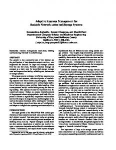
it is granted to transmit a packet upstream, observing the time delay that was established during the ranging procedure. Of course, this requires synchronization between upstream and downstream packet rates. For the HARMONICS PON, this can be generalized to a symmetry restriction: in-band signaling is only possible if the upstream channel can be identified from the downstream channel containing the permit. Obviously, the granted ONUs must be able to receive this “control” channel. In HARMONICS, the upstream and downstream channels are related one on one, but the available bandwidth downstream is twice the amount upstream. Synchronization is preserved by using 1.28- s packets in both directions. The access control for the optical switch is decoupled from the user plane, since this device only operates at the physical layer. 6) QoS Assessment: In the HARMONICS OFN, two classes of upstream traffic are possible: traffic with dynamic allocation of bandwidth in the OFN as, e.g., BE and traffic with a static allocation with better guarantees and a reserved bandwidth. Both differ in the manner they receive permits from the OLT. For dynamically allocated traffic, ONUs can indicate their demand for access by attaching requests to the upstream packets after which the central controller can decide which ONU can send packets. Unlike the OLT, however, the ONUs first need to have access in order to transmit a packet in the first place. To solve this problem, PONs often use minislots—special packets allowing a number of ONUs to submit their requests. By frequently issuing permits for these minislots, the OLT can poll the ONUs. An ONU can submit subsequent requests by means of piggybacking, attached to packets that were granted previously. This method is especially useful for bursty traffic. Minislots must be assigned frequently to enable small delays, which introduces considerable overhead. Yet, a request may not automatically result in a permit, especially under high-load situations. This is resolved by keeping track of outstanding requests from each ONU. These shadow counters, which need to be synchronized with the request/permit balance of every ONU, complicate the access controller. Because of the large number of ONUs in the OFN, HARMONICS uses this kind of dynamic requests only for BE services where delay is less critical. Forstatically allocated traffic, the controllersends permits with a fixed rate to the ONUs based on reservations (these are made via the flow management framework, which will be explained subsequently. As such, this traffic receives a fixed reserved upstream bandwidth and can be used for services that need higher QoS than BE. The rationale behind this choice is that even under moderate traffic loads, bursts from a number of ONUs can—and in practice will—overload the system. This forces the controller to spread out the permits in time, effectively resulting in a CBR service. This fundamentally prohibits PONs, or any other shared medium, from giving any guarantees for bursty traffic, unless it is allocated at peak rate. To reduce the loss of unused permits, the ONUs can transfer these to the dynamic service class (BE). Obviously, the efficiency is highly improved when traffic is already shaped to a CBR (by the HLRs which police the incoming traffic based on the active reservations). Fig. 2 shows a comparison of the traffic dynamics at the ONUs for the dynamic method (BE) that was described previously [Fig. 2(a)] and the static allocation [Fig. 2(b)]. The
2596
JOURNAL OF LIGHTWAVE TECHNOLOGY, VOL. 22, NO. 11, NOVEMBER 2004
Fig. 2. Dynamic versus static allocation of upstream optical packets. (a) Dynamically requested permits by the ONUs. When a packet is received from the HLR, requests are sent upstream and the central controller sends permits when bandwidth is available. (b) Statically reserved permits. The central controller sends permits to the ONUs based on the reserved bandwidth. Requests for permits are not sent by the ONUs.
Fig. 3.
QoS classification and queuing at the ONU for upstream traffic.
major benefit of static allocation is that it allows for service guarantees, independent from the traffic in the rest of the optical network. 7) Queuing in the ONUs: When packets arrive at the ONU from the HLR (Fig. 3), they are classified according their QoS class (see Section III-C) and stored in a first-in-first-out (FIFO) queue and segmented. A slave controller transmits a segment upon receiving a permit from the central controller. Although data is transmitted connectionless, e.g., to an arbitrary receiver at the OLT, the MAC must ensure that all segments from one IP packet end up at the same receiver to avoid extra switching at the OLT side to reassemble the IP packet. To avoid interrogations to establish the length of each packet, which would cause round-trip delays, the packets are stored in different queues, each dedicated to a particular receiver. The master controller at the OLT can address permits to the different queues in a
round-robin order, ensuring that the queues are serviced equally. The ONU ensures that a load balancing function evenly fills the queues with packets coming from the HLR. To ensure that each queue experiences a sufficient permit rate, the OLT can signal the ONU to use a smaller number of queues. The same would be necessary when an OLT receiver requires maintenance or is used for ranging on another channel. 8) QoS Scheduling: The HARMONICS OFN shares the same functionality as an optical network switch. All data is buffered electronically at the ONUs, resulting in a queueless optical switch fabric at the OXC. The main task of the scheduler is to ensure that both reserved IP flows (static traffic) and BE (dynamic) traffic are processed according to their priorities and without introducing additional delays. Because the HARMONICS PON behaves like a two-stage switch, rather than several single-wavelength PONs in parallel,
VERMEULEN et al.: IP-BASED DWDM ACCESS NETWORK RESOURCE MANAGEMENT
Fig. 4.
2597
Access control architecture for the PON for the upstream case.
it is not possible to adopt conventional time-spacing schedulers such as global FIFO [9]. Because of the OXC, the different TDM schemes are dependent. To enable flexible switching, allocation is performed on a per-packet basis, which needs to be coordinated globally. The overview in Fig. 4 shows a series of virtual queues (VQs), which contain permits for each ONU queue in the system. The static VQs are programmed by the resource manager (via the flow management framework) and administer the permits sent to the ONUs for the static PON traffic. The dynamic VQs are triggered by requests from the ONUs for dynamic traffic, such as BE. Additional VQs are configured for PON operation and maintenance (OAM) and ranging. The scheduler performs the selection of all the VQs, accounting for the priority from I to IV. The permits that remain are broadcasted on the proper transmitter, and the OXC is updated. The challenge of the scheduler, as with all fine-grain packet switches that operate at gigabit speeds and beyond, is to deal with a large amount of queues. The number of ONU queues , with being the number of ONUs, equals the number of service classes, and the number of receivers. For the reference architecture with eight receivers at , 1024 ONUs , and two the OLT classes (statically allocated and dynamically allocated), this results in 16 384 queues. Load balancing of incoming permits in the ONUs among the different receiver queues reduces this number to 2048, which is still a formidable amount. Here is an example to illustrate this challenge: a conventional PON scheduler, allocating microsecond time slots on a single medium channel to one of 16 ONUs has to consult requests at a rate of 60 ns when a simple round-robin mechanism is used. For a system of the proposed scale, a round-robin scheduler would require subnanosecond 1.28 s 16 384 78 ps clock cycles, which is very hard and expensive to realize with conventional hardware. For this reason, a self-routing scheduler architecture has been designed.3 The scheduler is capable of evaluating the 3“Distributed scheduler for packet switches and passive optical networks,” U.S. Patent 2002/0 075 884 (pending).
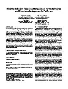
requests, originating from either dynamic or static traffic, for many queues in parallel. It reduces the complexity from an order (virtual output queues per time slot) to , which results in a cycle time of 45.7 ns. 9) Simulation Results: Simulations (Fig. 5) of the OFN discrete-event simulator MAC were done in the OMNeT [10] for upstream traffic with a large number of constant bit rate and variable bit rate sources connected to the ONUs and a sink connected to the OLT. The static traffic, for which bandwidth is reserved, has a low delay with almost uniform distribution (guaranteed quality), while the dynamic traffic has larger delays with a bigger variation. C. Mapping DiffServ QoS (L3) to the Optical Feeder QoS (L2) The HARMONICS architecture is DiffServ-based at layer 3 to allow applications and users to select the network service that best suits their needs. DiffServ defines node services in terms of the forwarding behaviors (PHB) of which EF, AF, and BE are standardized (see also Section III-A). The MAC at layer 2 in the OFN, on the other hand, considers only two kinds of traffic: traffic with certain QoS constraints which has to be reserved by means of the flow management framework and traffic for which dynamic permits are requested by the ONUs and for which no QoS can be guaranteed. The former is traffic such as EF and AF, which needs fast service and has resources reserved to avoid losses, high delays, and jitter. The latter is traffic (such as BE), which does not have QoS constraints and can be served whenever there is a wavelength and time slot available. Note that for the downstream case, EF, AF, and BE traffic receive the same QoS once they are in the PON, but a differentiation is made at the HARMONICS edge router, which has DiffServ functionality and as such prioritizes EF over AF over BE. For the upstream case, however, EF and AF traffic is queued in the static queues (Fig. 3) for which permits are generated automatically, while BE traffic is stored in the dynamic queues for
2598
JOURNAL OF LIGHTWAVE TECHNOLOGY, VOL. 22, NO. 11, NOVEMBER 2004
Fig. 5. Histograms showing the simulated probability density function dP and cumulated density function P for the delay of upstream traffic in the OFN for static traffic (with reservation, left) and dynamic traffic (BE, right).
which permit requests have to be sent. Hence, upstream, differentation between EF, AF, and BE is made both at the HARMONICS leaf router and in the PON. The leaf routers map the IP packets to the right L2 QoS class and mark the packets so they can be classified in the ONUs.
less performing than CORBA. Because of the importance of the traffic between the different management components, we have adapted omniORB [11] and Orbacus [12] ORB implementations so that CORBA messages are IP packets marked with the DiffServ EF DSCP. A. Layer Networks and Layer Network Coordinators
IV. END-TO-END QoS FLOW MANAGEMENT To set up end-to-end flows with strict QoS guarantees, all networks along the path should be informed and queried (admission control) if a new flow can be provided. e.g., for DiffServ domains, this encompasses the configuration of leaf routers (classifiers, DSCP markers, shapers, policers, etc.) upon a positive response of the admission control for that domain. For the OFN, admission control and the subsequent configuration of the MAC protocol has to be fulfilled. This functionality has not been standardized yet for DiffServ and is certainly not standardized to support end-to-end QoS over networks of multiple technologies. A major achievement of the project was the design and specification of a distributed management framework which fulfills these tasks. In addition, a prototype of this framework was developed. Note that this flow setup and tear-down phase is only needed for flows with a higher QoS than BE traffic and will only be needed for the minority of the traffic. Details about scalability issues and feasibility will be provided further on in this section. The communication between the management components is based on the common object request broker architecture (CORBA). Key motivations for using CORBA are the following: CORBA provides an object-oriented framework with a superior distribution paradigm in which every object could be potentially distributed. This feature comes in very handy when we want to build an architecture based on logically centralized but physically distributed components. CORBA exhibits also standard mappings to multiple object-oriented programming languages based on a common language for the definition of the interfaces, namely interface definition language (IDL). This feature makes it really easy to mix multiple languages and platforms into one system. Recent technologies as .NET or J2EE are comparable in functionality but are less mature and
To ease the end-to-end coordination and management of different administrative domains and technologies, a generic layering and hierarchy model was introduced following the divide et impera concept. The architecture and used terminology is aligned with proposals by the Telecommunications Information Networking Architecture (TINA) Consortium [13]–[16] but adapted to be more consistent and applicable. The most important concept is the layer network (Fig. 6). A layer network is a network consisting of a single technology (e.g., DiffServ or VDSL) and is restricted to a single administrative domain (e.g., an operator). One domain can contain several layer networks, each with another technology, as shown in the figure. Within the TINA Consortium, the term layer network is used to describe all network equipment of one technology in the whole world, but this is not a useful definition because of scalability issues. Separate layer networks can have various relationships with each other, as shown in Fig. 6. In the figure, both network layers 2 and 3 have the same administrative domains, which is only not to overload the figure. It would be perfectly possible, e.g., that administrative domains 1 and 2 at L3 are only one administrative domain owned by one provide, and as such there would be only one DiffServ layer network. The white arrows depict a possible user-to-user flow as studied in the HARMONICS project. At layer 3, only DiffServ is used, while at layer 2 a variety of technologies exist. Because the core networks are generally using point-to-point links at layer 2, they are described as “optical core networks” in the figure, as their layer 2 (QoS) management falls outside the scope of this paper and a QoS mapping between L2 and L3 is not needed, as already noted in Section III. The figure shows that there are two types of interworking between two peer-to-peer layer networks of a different technology: if one of the higher layers (e.g., layer 3) in a peer-to-peer
VERMEULEN et al.: IP-BASED DWDM ACCESS NETWORK RESOURCE MANAGEMENT
2599
Fig. 6. Layers, administrative domains, layer networks (LN), and their relationships.
Fig. 7. Layer networks and LNCs within the HARMONICS project with Hiperlan/2 as an example of a last-mile technology.
layer network interworking relationship (e.g., OFN and VDSL) does not need interworking, because it is a federation context (e.g., DiffServ at Layer 3) or because it concerns only one layer network, then the higher layer network equipment (e.g., an IP router) can have two different lower layer interface cards (e.g., VDSL termination and optical). If the higher layers are also interworking (e.g., layer network 5 and 6), then a new piece of equipment [an interworking unit (IWU) or gateway] has to be developed. In this project, the HARMONICS leaf and edge routers are interworking units of the first type. A logical next step in the concept of layer networks is to introduce the layer network coordinator (LNC) as a software entity responsible for the coordination of flow setup and teardown in a single layer network and the negotiation with neighboring layer networks. Here, we see why this terminology as used in the TINA specifications—one LNC for the whole world—is not very logical, in view of the structure of the Internet with the different domains. The LNCs are technology dependent and are
only logically a single component. Practically, they can be distributed by advanced distributed software techniques and loadbalancing algorithms, which make a scalable approach possible. Applied to the HARMONICS project, Fig. 7 shows the different layer networks with their respective LNCs. This is the reference architecture that will be described in detail in the following sections. On top of the LNCs, optionally a service management architecture as described in [17] can be used to negotiate QoS matching at the application level (e.g., videoconferencing codec parameters). B. DiffServ Layer 3 Multiple-Domain Management As already slightly described in Section III-A, there are three types of DiffServ routers of which the functionality and location in the network is shown in Fig. 8. From the listed functionality, it seems logical to define a long-term policy management and a short-term flow management.
2600
Fig. 8.
JOURNAL OF LIGHTWAVE TECHNOLOGY, VOL. 22, NO. 11, NOVEMBER 2004
DiffServ leaf, edge, and core routers: location and functionality.
The policy management comprises the policies of a particular domain (e.g., which DiffServ classes have to be supported in the core routers), the rather static SLAs between the different administrative domains (e.g., peering agreements for each DiffServ class), and the SLAs with customers in the access domains (e.g., the customer can set up flows with a particular Diffserv class till max. 15 Mb/s with a blocking probability less than 0.01). These policies and SLAs are thus longer term contracts and affect the network dimensioning and the configuration of edge routers between domains. The flow management on the contrary is per-flow based, is time critical, and is much more dynamic than policy management. To set up a flow, two things have to be done at the DiffServ layer: end-to-end flow admission control (FAC)4 and configuration of the first leaf router on the path of the new flow (e.g., a DSCP marker, policer, and, if desired, a shaper, but this can be an extra service). Edge routers do not have to be configured as they work on a behavior aggregate level and are configured by long-term policy management. However, the SLA at the edge of the domain has to be checked if a new flow can be accepted. The LNC (layer network coordinator for DiffServ)
coordinates this in its own domain and also contacts LNC s of peering layer networks if necessary. Fig. 9 shows a typical end-to-end situation and the federation relationships from a DiffServ layer 3 viewpoint (for simplicity, LMNs are not drawn explicitly). Of course, instead of a backbone of only one provider, multiple backbones (and, hence, multiple layer networks) could be drawn5. The LNCs for the access feeder networks (domains 1 and 3) are logically and physically centralized in their respective domains as this imposes no scalability problems. The LNC for the core network, however, is physically distributed, as will be explained hereafter.
Per-flow management immediately triggers some possible scalability alarms. However, we cope with the issues in the same way as DiffServ tackles them, namely by moving the processing to the edges. Therefore, instead of using one LNC component in the core domains, several components are installed, each responsible for one or more ports on the edge routers. Those components do FAC for their edge ports only (without any configuration of the router) and not for the core
4IP is in se connectionless, so connection admission control (CAC) is a bad term. However, there is always a concept of flow, which means a stream of closely related packets, e.g., for a videoconferencing session.
5Note, however, that an average flow through the current Internet crosses about one or two backbones and two access networks, which can be checked on various traceroute websites.
C. Scalability of Flow Management
VERMEULEN et al.: IP-BASED DWDM ACCESS NETWORK RESOURCE MANAGEMENT
2601
Fig. 9. End-to-end layer 3 flow management: an LNC for each layer network (PoP = point of presence = edge router).
network itself as the peering contracts for QoS classes are likely (or can be chosen as such) to be much smaller in capacity than the core network. Of course, FAC for the core bandwidth itself would also be possible, but here throwing in more bandwidth seems to be more cost efficient than doing, e.g., bandwidth monitoring and FAC per flow. This is, of course, not true for access domains, which were studied within HARMONICS. A typical flow setup scenario might look like this (Fig. 9): a user in domain 3 wants to start a videoconferencing session with a user in domain 1 and requests his LNC [by means of, e.g., RSVP or CORBA, which can be integrated in the application or via a separate graphical user interface (GUI)] for an end-to-end flow. The latter looks up its routing information [typically this routing information will be gathered from the border gateway protocol (BGP)] to know which component in the core domain has to be contacted, which will in turn contact the LNC component of the outgoing port of the core domain. This component then contacts the LNC of domain 1. Each LNC performs FAC, and the first LNC configures the leaf router near the user. In case of an underlying network (client–server relationship), which has to be configured to cope with the new flow, e.g., in case of the access feeder networks, the underlying LNC has to be contacted, which will take care of the configuration in its layer network (Fig. 7). (For more detailed scenarios and IDL interfaces, we refer to [18].) Because applications such as videoconferencing and video-on-demand (VoD) cannot be used on a large scale today, no detailed numbers are known on QoS traffic demand, and thus it seems difficult to estimate scalability. However, we can take the public-switched telephone network (PSTN) as an example, for which a lot of dimensioning expertise exists [19]. The PSTN is circuit switched with circuits of 64 uncompressed voice . Typical peering connections in kb/s today’s Internet (http://www.mae.net, http://www.euro-ix.net) are based on 100-Mb/s, 1-Gb/s, OC-3, OC-12, OC-48 Ethernet, frame relay, or ATM connections.
Imagine that we would use all that bandwidth for voice calls. 100 Mb/s equals 1562 circuits of 64 kb/s. With a typical grade-of-service (blocking probability) of 0.01, the Erlang-B formula [19] says that 1562 circuits can support a load of 1533 Erlang.6 With a typical call holding time of 150 s, this results in 36 792 voice calls/h = 10.22 calls/s. only 1533 3600/150 Therefore, the management framework should be able to cope with ten flow setups and teardowns per second. To give an idea, a business user generates approximately 0.03–0.06 erlang during the busy hour; therefore, 1533 erlang would equal the load of 51 000 business users. For 1 Gb/s, this gives 15 620 circuits with 15 702 erlang (approximately 500 000 business users) and 105 voice calls/s. 10 Gb/s gives approximately 1000 voice calls/s and equals the telephone traffic of a group of 5 million business users during the busy hour. Measurements (see further) with the developed prototype of the management framework running on modest workstations (AMD 1.6-GHz single processor) show that 1500 flows/s can be set up, resulting in the processing of approximately 750 voice calls/s, which means that approximately 7.5 Gb of typical voice traffic could be set up and torn down by our prototype (and thus also by each component individually for its domain). However, typical broad-band and multimedia applications such as videoconferencing, VoD, and virtual private networks will have the following characteristics: 1) use more bandwidth than 64 kb/s; 2) take longer than 150 s; 3) be only a fraction of the total Internet traffic (BE traffic will still be the largest part). Therefore, for the same used bandwidth, less flows will have to be set up and torn down. If we, e.g., suppose that a videoconferencing call takes 1 Mb/s in one direction, lasts about 10 6Erlang is a unit without dimension, accepted internationally for measuring the traffic intensity. This unit is defined as the aggregate of continuous occupation of a channel for 1 h (3600 s). An intensity of 1 erlang means the channel is continuously occupied.
2602
JOURNAL OF LIGHTWAVE TECHNOLOGY, VOL. 22, NO. 11, NOVEMBER 2004
min, and 50% of all Internet traffic is used for QoS traffic, then a load of 750 video calls/s on one component means a total load 450 000 erlang which needs, with a blocking of 750 600 probability of 0.01, approximately 450 000 circuits of 1 Mb/s or 450 Gb/s, and this is only 50% of all traffic, so that one component on one workstation could be responsible for peering ports on edge routers, which total 0.9 Tb/s of traffic. As such, it seems reasonable to say that this approach of per-flow admission control is scalable enough by introducing multiple components that make up one logical LNC , up to one component per port on the edge routers. D. Optical Feeder Resource Management As described in Section III-B, the HARMONICS optical access feeder also supports QoS and a mapping from DiffServ QoS to the OFN dynamic and static class has been defined. Three entities are responsible for the flow management in the OFN (Fig. 7). takes control of the OFN specific policy conThe LNC figuration of the HARMONICS edge and leaf routers and converts the L3 IP addresses to L2 ONU numbers before forwarding new flow requests to the resource manager (RM). The HARMONICS edge router has to be configured with a forwarding table in which the destination ONU number is mentioned so that the edge router can mark the downstream packets for the OLT. The HARMONICS leaf router has a configurable table with a mapping from DiffServ DSCPs to the OFN QoS classes, which is needed for marking upstream packets with the right QoS class so that the packets can be queued accordingly in the ONUs. The DiffServ-specific configuration of the HARMONICS edge and leaf routers is done by the LNC of course. For downstream flow setup, the LNC does nothing, because admission control is fully done by the LNC , and if the HARMONICS edge router can cope with a new flow, then the OFN will also accept it without any configuration in the OFN. Upstream flow setup or teardown requests are forwarded to the RM. The RM has a link-oriented control of the OFN. The RM performs the FAC for the OFN by accepting/rejecting new upstream prioritized flows (BE traffic is handled by dynamic permit requests by the ONUs) according to the QoS, the available re. The RM sources, and the requests received from the LNC communicates the allocation of resources needed for the prioritized flows to the MAC, which performs the actual assignment of wavelength channels and time slots by transmitting static permits. The MAC has a packet-oriented control of the OFN and was described in more detail in Section III-B. V. FIELD TRIAL SETUP AND RESULTS A field trial was organized to test the overall system with real applications and real users. The field trial was especially addressed to the functionality and performance of the management framework and the impact of QoS between multiple technologies. The optical components were tested separately in a laboratory trial [3] because not all components were developed in the project.
The system used in the HARMONICS field trial is depicted in Fig. 10. Three different locations in Germany are used: a small DiffServ network in Darmstadt which is administrative domain 1, the Winterfeldstrasse location in Berlin containing an edge router and an OFN emulator, and the Atrium in Berlin containing the LMNs connected to the leaf routers. The latter two locations are part of administrative domain 2 and are located in an area of which the size could be covered by a real HARMONICS system. The connection between Darmstadt and Berlin (a distance of 750 km) is made up of two MAN environments in Berlin and Darmstadt, which are connected over a wide-area network (WAN) using Ethernet over WDM technology. Both MANs were designed with optical-switched Ethernet technology and consist of Ethernet-carrier-class equipment. The connections between the two locations in Berlin (a distance of about 7 km) are based on single-mode optical fiber with gigabit Ethernet. The OFN emulator is an emulation of the OFN and the MAC which behaves to the outside (edge, leaf routers, control plane) as a real system, and which is internally implemented on a perslot basis (e.g., for delay emulation). As the field trial only contains two ONUs (in the OFN emulator emulated as they are sharing the same wavelength, which is the most challenging from a MAC viewpoint) and two leaf routers, Gb/s Ethernet can provide the same bandwidth as a wavelength channel in a real system. The platforms used for the OFN emulator and the routers are high-end dual processor (1.266-GHz) Linux PCs running Click. The Click Modular Router Project [20] is Open Source software developed by the MIT and can be used to easily develop routers (or, more in general, packet processing entities) in a modular way with the needed functionality based on off-the-shelf PC hardware. On top of this modularity, the performance is also very high (in comparison to Linux) because of the use of adapted polling network drivers. The aforementioned PC hardware can, for example, forward 1.4 Gb/s in a QoS aware router configuration. This platform was used since commercial routers did not support the DiffServ technology in a standardized manner during the project (especially from a management viewpoint, e.g., through SNMP [21]). The latter also could not be extended with extra functionality as needed for the OFN. The routers in the field trial supported both IPv4 and IPv6, but all used multimedia applications were still IPv4. The OFN itself is a layer 2 technology and as such can support both IPv4 and IPv6. Management components were distributed over five Linux management stations (AMD 1900 1.6 GHz) and are implemented in C++/omniORB [11] with JAVA/Orbacus [12] GUIs. Fig. 10 also shows flow setup times and rates for flows from the VoD server in domain 1 to a VDSL terminal in domain 2. Higher setup rates than 1500 flows/s are impossible due to the CPU load on the management stations. The figure shows the CPU load of MS 2. The field trial setup contained six different last-mile technologies (Fig. 10), and several applications were tested. VoD was possible from two different servers and in several qualities (DVD MPEG 2 at 8–10 Mb/s, DivX at 1 Mb/s, MPEG 2,
VERMEULEN et al.: IP-BASED DWDM ACCESS NETWORK RESOURCE MANAGEMENT
2603
Fig. 10. Functional overview of the field trial setup and performance of the management framework for setting up flows from the VoD server in domain 1 to a VDSL terminal in domain 2.
Fig. 11.
End-to-end one-way QoS measurement with four BE and three EF flows.
and MPEG 1). One of the VoD servers was multicasting live television channels captured from the DVB-T project in Berlin. Online gaming was an ideal delay critical application. Further on, Microsoft Netmeeting and web browsing could be used. Because all these applications are closed source, a separate web-based GUI made it possible for the users to reserve bandwidth for the applications they wanted to use. Both quantitative experiments with Spirentcom Smartbits packet generators and qualitative experiments with friendly users were performed during the field trial.
Performance and QoS measurements were done with Smartbits devices, and Fig. 11 shows a typical setup in which upstream QoS between multiple flows with congestion is tested as shown in the figure. In total, seven flows are used, three times BE and EF flows (in total 300 Mb/s) from the leaf routers to domain 2 in Darmstadt and back via a separate network and one flow (1 Gb/s) from LR2 to LR1. As expected, when bandwidth is reserved for EF traffic, the packet loss is zero for EF, and only BE traffic is dropped, as can be seen in Fig. 12. Without reservations, all flows are treated equally.
2604
Fig. 12.
JOURNAL OF LIGHTWAVE TECHNOLOGY, VOL. 22, NO. 11, NOVEMBER 2004
Upstream packet loss in case of congestion. (a) Without bandwidth reservation. (b) With bandwidth reservation for the three EF flows.
Feedback from the friendly users says that QoS is useful in times of congestion and works very good, but it seems that the manual reservation of bandwidth via a dedicated GUI is too complex. The flow setup should be integrated with the applications, which is not straightforward as most applications are closed source. Another interesting result of the questionnaire was that only half of the users were interested in, for example, VoD or videoconferencing if they would have to pay. VI. PROBLEMS AND SOLUTIONS During the field trial, some other problems were discovered as well. The initial problem was that packets of single flows were reordered in the upstream direction in the OFN because the packets were queued in different queues at the ONUs and sent to different burst-mode receivers (BMRs). Although IP does not guarantee that packets arrive in order, it is better to avoid reordering, as it has a serious negative impact on, for example, transport control protocol (TCP) throughput (because of retransmits, among others) or user datagram protocol (UDP) applications, which have to buffer the packets to reorder them. A possible solution is to reorder the packets at the OLT. Another possible solution would be to send all packets of one flow to the same queue by means of, for example, a hash function in the ONU, but flows are characterized at L3, so this would mean layer violation. Another problem is that statically allocated large upstream packets can have a considerable delay: e.g., with a reservation of 250 kb/s, permits for 86-B upstream slots are sent by the OLT every 2.75 ms, resulting in, for example, a delay of 49.5 ms for a 1500-B packet. However, this is odd if, for example, a voice-over-IP (VoIP) application first waits until 1500 bytes of samples are collected, and then it takes another considerable amount of time until the packet reaches the receiver. It would be better that a 1500-B packet is sent at line speed and that the interpacket time is adjusted to 250 kb/s. This is, of course, a consequence of the use of 100-B slots. However, two workarounds are possible: use smaller packets (which is not possible for TCP traffic as the application has no control over the packet size, although most time-critical applications use UDP) or reserve more bandwidth. It was also noted during the field trial that some multimedia applications such as VoD are still not robust enough to cope with
some packet loss or delay variations and thus are only really stable in unloaded networks. VII. CONCLUSION This paper described the network architecture and the accompanying end-to-end QoS resource management framework as studied in the HARMONICS project in the context of the European Union IST Program. HARMONICS aims at addressing the following challenges: convergence of today’s access networks, the increasing demand for more capacity, pushing fiber deeper into access networks, and the possibility to have strict guarantees about the quality of the network. To tackle these issues, a novel DWDM-based OFN and a flow management framework are designed and developed, providing end-to-end QoS by using IPv4/IPv6 DiffServ at layer 3. At layer 2, a novel MAC protocol is proposed for the HARMONICS OFN, supporting both time slot and wavelength allocation while guaranteeing QoS. A description of the QoS mapping between DiffServ and the OFN is also given. For the LMNs, advanced technologies such as VDSL or Hiperlan/2, which support QoS, are used but their layer 2 QoS and the QoS mapping are not addressed in this paper. The flow management framework is able to generically support a very wide variety of network technologies, both in peer-to-peer as in client–server relationships, not only restricted to optical networks as demonstrated in this paper. A prototype was developed, and it was shown that per-flow reservation of resources is feasible and scalable with the proposed approach. Finally, a field trial with experiments and users has proven the feasibility with real applications and has also revealed some issues that have been solved or can be worked around. It was concluded from the project that overprovisioning can be a solution for core networks, but that QoS in access networks or in access feeder networks offers big advantages and possibilities. REFERENCES [1] HARMONICS Project [Online]. Available: http://ist-harmonics.atlantis.UGent.be [2] K. Steenbergen, F. Janssen, J. Wellen, R. Smets, and T. Koonen, “Fast wavelength-and-timeslot routing in hybrid fiber-access networks for IP-based services,” presented at the IEEE LEOS Symp., Delft, The Netherlands, Oct. 2000.
VERMEULEN et al.: IP-BASED DWDM ACCESS NETWORK RESOURCE MANAGEMENT
[3] A. Geha and J. Wellen, “Harmonics, a novel optical system,” presented at the IEE Photonic Access Technologies 2002, London, U.K., Dec. 17–18, 2002. [4] K. Nichols, V. Jacobson, and L. Zhang, “A Two-Bit Differentiated Services Architecture for the Internet,” in Internet Engineering Task Force RFC 2638, July 1999. [5] S. Blake et al., “An architecture for differentiated services,” presented at the Internet Engineering Task Force RFC 2475, Dec. 1998. [6] K. Nichols, S. Blake, F. Baker, and D. Black, “Definition of the differentiated services field (DS field) in the IPv4 and IPv6 headers,” presented at the Internet Engineering Task Force RFC 2474, Dec. 1998. [7] V. Jacobson, K. Nichols, and K. Poduri, “Expedited forwarding PHB,” presented at the Internet Engineering Task Force RFC 2598, June 1999. [8] J. Heinanen et al., “Assured forwarding PHB group,” in Internet Engineering Task Force RFC 2597, June 1999. [9] C. Blondia, O. Casals, and J. Garcia, “A cell based MAC protocol with traffic shaping and a global FIFO strategy,” presented at the RACE Open Workshop Broadband Access, Nijmegen, The Netherlands, June 1993. [10] OMNeT++ Discrete Event Simulation System. [Online]. Available: http://www.omnetpp.org [11] omniORB C++ ORB. [Online]. Available: http://omniorb.sourceforge.net [12] Orbacus C++ and JAVA ORB. [Online]. Available: http://www.orbacus.com [13] M. Lapierre et al., The TINA Book, A Co-Operative Solution for a Competitive World. Englewood Cliffs, NJ: Prentice-Hall, 1999. [14] M. Yates et al., TINA Business Model and Reference Points Version 4.0: TINA-C document, May 1997. [15] C. Abarca et al., Network Resource Architecture Version 3.0: TINA-C document, Feb. 1997. [16] N. Natarajan et al., Network Resource Information Model Specification Version 3.0: TINA-C document, Dec. 1997. [17] F. Vandermeulen, F. Steegmans, B. Vermeulen, S. Vermeulen, and P. Demeester, “An end to end QoS discovery architecture embedded in a TINA based multimedia platform,” presented at the 5th IEEE Symp. Computers Communications (ISCC 2000), Antibes, France, July 2000. [18] B. Vermeulen, S. Vanhastel, J. Wellen, C. Mas, F. Scholaert, B. Dhoedt, and P. Demeester, “A generic end-to-end distributed QoS management architecture and its application to IP-diffserv over a WDM access feeder network,” presented at the IEEE Network Operations Management Symp. (NOMS 2002), Florence, Italy, Apr. 2002. [19] S. Keshav, An Engineering Approach to Computer Networking: ATM Networks, the Internet and the Telephone Network. Reading, MA: Addison-Wesley, 1997. [20] E. Kohler, R. Morris, B. Chen, J. Jannotti, and M. F. Kaashoek. (2000, Aug.) The click modular router. ACM Trans. Comput. Syst.. [Online], pp. 263–297
2605
[21] F. Baker, K. Chan, and A. Smith, “Management information base for the differentiated services,” in Internet Engineering Task Force RFC 3289, May 2002.
Brecht Vermeulen, photograph and biography not available at the time of publication.
Jeroen Wellen (M’98), photograph and biography not available at the time of publication.
Frank Geilhardt, photograph and biography not available at the time of publication.
Erik Weis, photograph and biography not available at the time of publication.
Carmen Mas, photograph and biography not available at the time of publication.
Bart Dhoedt (M’01), photograph and biography not available at the time of publication.
Piet Demeester (M’89–SM’98), photograph and biography not available at the time of publication.