Jan 21, 2003 - In Chapter 3 we describe the results from the analysis of the ionization and calibration ...... the Strips. A complex chain of readout lines is in charge to carry the signals from the MB ..... the nonâuniformity origin and to suggest a solution. In Section 2.3.2 the ...... Manuals and reference books ... Schaum, 1965.
` degli Studi di Milano Universita ` di Scienze Matematiche, Fisiche e Naturali Facolta
Dottorato di Ricerca in Fisica
21/01/2003
CERN-THESIS-2003-033
Energy reconstruction and calibration algorithms for the ATLAS electromagnetic calorimeter
Coordinatore: Prof. Rodolfo Bonifacio
Tutore: Prof. Luciano Mandelli
Tesi di Dottorato di
Marco Delmastro XV Ciclo
Anno Accademico 2001-2002
Energy reconstruction and calibration algorithms for the ATLAS electromagnetic calorimeter by
Marco Delmastro A Thesis Submitted in Fulfillment of the Requirements for the Degree of
“Dottore di Ricerca” (Doctor of Philosophy) in the Department of Nuclear and Subnuclear Physics University of Milano
This thesis has been defended on January 24th 2003 in Milano in front of the jury composed by: Prof. L.Mandelli. Supervisor. Dipartimento di Fisica, Universit` a degli Studi di Milano
Prof. S. Centro. Referee. Dipartimento di Fisica, Universit` a degli Studi di Padova
Prof. W. E. Cleland, Third Member. Department of Physics and Astronomy, University of Pittsburgh
c Marco Delmastro, 2002
` degli Studi di Milano Universita All rights reserved. This thesis may not be reproduced in whole or in part, by photocopying or other means, without the permission of the author.
Introduction ATLAS (A Toroidal LHC ApparatuS) [2] is a general purpose detector presently under construction. It will operate on the proton–proton collider, the Large Hadron Collider (LHC) [1], that will be installed in the LEP tunnel at CERN. LHC will provide a 14 TeV center of mass energy collision at a luminosity up to L ' 10 34 cm−2 s−1 , with a bunch crossing frequency of 40 MHz. ATLAS is a multi–purpose detector, with a large discovery potential for new physics such as Higgs bosons and Supersymmetric particles (SUSY) [5]. In most of these channels a crucial role in energy and position reconstruction of electrons and photons is played by the electromagnetic calorimeter (EMC). This is the case for example in the decay channels of the Standard Model (SM) Higgs boson H → γγ and H → e + e− e+ e− . The LHC experimental framework will impose severe constraints on the detectors in term of spatial coverage, response speed, radiation tolerance, background rejection capability, noise handing and time stability. The ATLAS EMC is a lead–liquid Argon (LAr) sampling calorimeter with an accordion geometry: this particular structure guarantees the full azimuthal coverage, while the LAr used as ionizing medium is intrinsically radiation tolerant and has a sensitivity that does not degrade in time. The system is provided with a fast readout that can cope with the LHC rate, and has been optimized to minimize the noise contributions coming from both electronics and pile–up. Each readout cell of the EMC can be calibrated with an embedded electronic system, that will be complemented at the LHC with a physics–based procedure. It has been shown [3] that a relevant contribution to the performances of the EMC comes from the precision achievable by the calibration procedure and the signal reconstruction technique. The work of this thesis has been devoted to the study, development and optimization of the algorithms of energy reconstruction and calibration of the EMC. A deep study of the electrical characteristics of the detector and of the signals formation and propagation is conduced: an electrical model of the detector is developed and analyzed through simulations; a hardware model (mock–up) of a group of the EMC readout cells has been built, allowing the direct collection and properties study of the signals emerging from the EMC cells. We study the existing multiple–sampled signal reconstruction strategy, namely the one used for the energy reconstruction of the EMC barrel prototype module data of 2000 test– beam. By comparing the results with the mock–up observations and the model simulations, we show the need of an improvement in order to reach the needed performances in terms
i
Introduction
of energy resolution and response uniformity. The optimal filtering (OF) technique is studied and implemented, taking into account the differences between the ionization and calibration waveforms as emerging from the mock–up analysis. A new calibration procedure that does not need any informations from the ionization signals as collected from the physics events in the EMC is proposed; its feasibility is investigated and discussed. An energy weighting technique is proposed to improve the EMC resolution and uniformity by recovering the energy lost by the developing electromagnetic shower in the upstream material and because of longitudinal leakage. The signal reconstruction and calibration procedures, together with the energy weighting technique, are extensively applied to the EMC production modules test–beam data of 2001 and 2002. Results, future improvements and the application to the full ATLAS experimental framework are discussed.
Outline of the work The LHC operating conditions and the ATLAS detector characteristics are reviewed in Chapter 1. Therein a short summary of the ATLAS physics program is given. The physics requirements on the EMC performances are discussed, mainly as driven by the Standard Model Higgs boson search. The EMC characteristics and operating features are discussed in Chapter 2. In Chapter 3 we describe the results from the analysis of the ionization and calibration signal formation and propagation through the EMC cells and readout chain. The multiple– sampled signal reconstruction techniques are discussed in Chapter 4, together with the connected electronics calibration strategies. The new calibration and signal reconstruction procedure is developed and discussed in Chapter 5. The energy weighting technique is exposed in Chapter 6. Results from extensive test–beam data analysis are presented and discussed in Chapter 7.
ii
Contents Introduction
i
Contents
iii
List of Figures
vii
List of Tables
xvii
1 The ATLAS detector at the LHC 1.1 The Large Hadron Collider . . . . . . . . . . . . . . . 1.1.1 Proton–proton collisions characteristics . . . . 1.1.2 LHC experimental challenges . . . . . . . . . . 1.2 The ATLAS Detector . . . . . . . . . . . . . . . . . . 1.2.1 Inner Detector . . . . . . . . . . . . . . . . . . 1.2.2 Calorimetry . . . . . . . . . . . . . . . . . . . . 1.2.3 Muon spectrometer . . . . . . . . . . . . . . . . 1.2.4 Magnets system . . . . . . . . . . . . . . . . . 1.2.5 Trigger and DAQ . . . . . . . . . . . . . . . . . 1.2.6 A short outline of the ATLAS physics program 2 The 2.1 2.2 2.3
2.4
liquid Argon electromagnetic calorimeter General description . . . . . . . . . . . . . . . . Segmentation and granularity . . . . . . . . . . Readout system . . . . . . . . . . . . . . . . . . 2.3.1 Signal generation . . . . . . . . . . . . . 2.3.2 Ground reference . . . . . . . . . . . . . 2.3.3 Readout lines . . . . . . . . . . . . . . . 2.3.4 Readout electronics . . . . . . . . . . . 2.3.5 Calibration strategy . . . . . . . . . . . LHC physics requirements overview . . . . . . .
. . . . . . . . .
. . . . . . . . .
. . . . . . . . .
. . . . . . . . .
. . . . . . . . . .
. . . . . . . . . .
. . . . . . . . . .
. . . . . . . . . .
. . . . . . . . . .
. . . . . . . . . .
. . . . . . . . . .
. . . . . . . . . .
. . . . . . . . . .
. . . . . . . . . .
. . . . . . . . . .
1 . 1 . 1 . 3 . 4 . 6 . 7 . 8 . 9 . 10 . 12
. . . . . . . . .
. . . . . . . . .
. . . . . . . . .
. . . . . . . . .
. . . . . . . . .
. . . . . . . . .
. . . . . . . . .
. . . . . . . . .
. . . . . . . . .
. . . . . . . . .
. . . . . . . . .
. . . . . . . . .
13 13 17 20 20 21 21 22 23 23
3 Electrical properties and signal shapes in the EMC 27 3.1 Foreword: the 2000 test-beam results . . . . . . . . . . . . . . . . . . . . . . 27 3.2 Detector models . . . . . . . . . . . . . . . . . . . . . . . . . . . . . . . . . 29
iii
Contents
3.3
3.4
3.5
3.6
3.7
3.2.1 Basic detector electrical model . . . . . . . . . . . . . 3.2.2 Detailed electrical model of an electrode channel . . . Hardware model of the EMC: the mock–up . . . . . . . . . . 3.3.1 General system layout . . . . . . . . . . . . . . . . . . 3.3.2 Injection circuits . . . . . . . . . . . . . . . . . . . . . 3.3.3 Electronic instrumentation and measurement methods Electrical parameters measurements on the mock–up . . . . . 3.4.1 Extraction of effective L and C values from impedance 3.4.2 Results from L and C measurements . . . . . . . . . . Signal measurements on the mock–up . . . . . . . . . . . . . . 3.5.1 Single physics injection . . . . . . . . . . . . . . . . . 3.5.2 Multiple physics injection . . . . . . . . . . . . . . . . Signals simulation . . . . . . . . . . . . . . . . . . . . . . . . 3.6.1 Effective detector description for simulation . . . . . . 3.6.2 Inductive ground return estimate . . . . . . . . . . . . 3.6.3 Results and comparison with measurements . . . . . . 3.6.4 Multiple physics injection . . . . . . . . . . . . . . . . Summary and perspectives . . . . . . . . . . . . . . . . . . .
4 Signal reconstruction algorithms study 4.1 Analysis of the “parabola” SR algorithm . . . . . . . . . . 4.1.1 Algorithm working principles . . . . . . . . . . . . 4.1.2 Test on mock–up signals . . . . . . . . . . . . . . . 4.2 Injection point correction . . . . . . . . . . . . . . . . . . 4.2.1 Basics . . . . . . . . . . . . . . . . . . . . . . . . . 4.2.2 Injection point correction on mock–up signals . . . 4.3 Electronic calibration using the optimal filtering technique 4.3.1 Basics . . . . . . . . . . . . . . . . . . . . . . . . . 4.3.2 Test-beam OF4 SR implementation . . . . . . . . 4.4 Summary and perspectives . . . . . . . . . . . . . . . . .
. . . . . . . . . .
. . . . . . . . . .
. . . . . . . . . . . . . . . . . . . . . . . . . . . . . . . . . . . . . . . . . . . . . . . . . . . . . . . . measurements . . . . . . . . . . . . . . . . . . . . . . . . . . . . . . . . . . . . . . . . . . . . . . . . . . . . . . . . . . . . . . . . . . . . . . . . . . . . . . . .
29 31 33 33 37 38 39 39 44 49 49 55 57 57 60 63 63 66
. . . . . . . . . .
. . . . . . . . . .
69 69 69 71 77 77 77 81 81 81 83
. . . .
85 85 86 88 89
. . . . . . . . . .
. . . . . . . . . .
. . . . . . . . . .
. . . . . . . . . .
. . . . . . . . . .
. . . . . . . . . .
5 A stand–alone SR and calibration procedure for the ATLAS EMC 5.1 Possible improvements in the OF SR procedure . . . . . . . . . . . . . . . 5.2 Ionization signal prediction . . . . . . . . . . . . . . . . . . . . . . . . . . 5.3 Parameters extraction from the calibration waveform . . . . . . . . . . . . 5.3.1 Calibration output transformation strategy . . . . . . . . . . . . . 5.3.2 Calibration pulse parameters through the step–response transformation . . . . . . . . . . . . . . . . . . . . . . . . . . . . . 5.3.3 Detector cell characteristic frequency through the cosine transformation . . . . . . . . . . . . . . . . . . . . . . . . . . . . . 5.3.4 Detector contact resistance through the injection–point correction residual oscillation minimization . . . . . . . . . . . . . . . . . . . 5.4 Parameters extraction from mock–up signals . . . . . . . . . . . . . . . . . 5.5 Parameters extraction from the test–beam 32–samples delay waveforms .
iv
. 91 . 93 . 99 . 102 . 107
Contents
5.6
5.5.1 5.5.2 5.5.3 5.5.4 Open 5.6.1 5.6.2
Master Waveform computation . . . . . . . . . . . . . . . . . Parameters extraction results . . . . . . . . . . . . . . . . . . Ionization signal prediction and OF coefficients computation A possible EMC calibration scenario at the LHC . . . . . . . questions . . . . . . . . . . . . . . . . . . . . . . . . . . . . . . Ionization signal prediction . . . . . . . . . . . . . . . . . . . Signals normalization and readout gain . . . . . . . . . . . .
. . . . . . .
. . . . . . .
. . . . . . .
. . . . . . .
107 111 120 126 127 127 128
6 Energy calibration using a layer–weighting technique 6.1 Energy losses estimate using a “toy” MC . . . . . . . . . . 6.2 Energy resolution minimization . . . . . . . . . . . . . . . . 6.3 Statistical fluctuations on the weights . . . . . . . . . . . . 6.4 Application to the EMB test-beam data samples . . . . . . 6.4.1 Normalization strategies . . . . . . . . . . . . . . . . 6.4.2 Weights patterns and symmetries . . . . . . . . . . . 6.4.3 Resolution improvements and measurement accuracy 6.5 Summary and perspectives . . . . . . . . . . . . . . . . . .
. . . . . . . .
. . . . . . . .
. . . . . . . .
. . . . . . . .
. . . . . . . .
. . . . . . . .
. . . . . . . .
. . . . . . . .
129 . 130 . 135 . 139 . 140 . 140 . 141 . 141 . 149
7 Energy response uniformity of the EMC 7.1 Energy response non–uniformity sources . 7.2 EMB modules test–beam setup . . . . . . 7.3 Data sample selection and analysis outline 7.3.1 Event selection . . . . . . . . . . . 7.3.2 Run and cell selection . . . . . . . 7.4 Uniformity of the production modules . . 7.5 Summary and perspectives . . . . . . . .
. . . . . . .
. . . . . . .
. . . . . . .
. . . . . . .
. . . . . . .
. . . . . . .
. . . . . . .
. . . . . . .
. . . . . . .
Conclusive remarks
. . . . . . .
. . . . . . .
. . . . . . .
. . . . . . .
. . . . . . .
. . . . . . .
. . . . . . .
. . . . . . .
. . . . . . .
. . . . . . .
151 151 152 154 154 160 163 165 167
A Signals description 171 A.1 Ionization signal . . . . . . . . . . . . . . . . . . . . . . . . . . . . . . . . . 171 A.2 Calibration signal . . . . . . . . . . . . . . . . . . . . . . . . . . . . . . . . . 172 A.2.1 A more detailed description of the calibration signal . . . . . . . . . 173 B Optimal filtering 177 B.1 About the need of additional filtering . . . . . . . . . . . . . . . . . . . . . . 177 B.2 Coefficients computation . . . . . . . . . . . . . . . . . . . . . . . . . . . . . 178 B.3 Transfer function of the OF . . . . . . . . . . . . . . . . . . . . . . . . . . . 181 Bibliography
183
Errata Corrige and Addendum
189
v
List of Figures 1.1
Layout of CERN LEP tunnel, including the future LHC infrastructures. . .
2
1.2
Tridimensional cut–away of the full ATLAS detector. . . . . . . . . . . . . .
5
1.3
Tridimensional cut–away view of the ATLAS inner detector system. . . . .
6
1.4
Tridimensional cut–away view of the ATLAS calorimetry system. . . . . . .
7
1.5
Tridimensional cut–away view of the ATLAS muon spectrometer system. .
9
1.6
Tridimensional pictorial view of the ATLAS magnets coils system. The central cylindrical coil of the superconducting solenoid is visible, surrounded by the air–core barrel and end–caps toroids coils. . . . . . . . . . . . . . . . 10
1.7
Operating principles of the ATLAS Level 1 trigger: informations flow from the ATLAS main sub-detectors (left); “Regions Of Interest” (ROI’s) (right); 11
1.8
Scheme of the ATLAS DAQ pipelines, along with the trigger levels. . . . . . 11
2.1
View of one half on the EMB cryostat. . . . . . . . . . . . . . . . . . . . . . 14
2.2
Detailed view of a EMB LAr gap section. . . . . . . . . . . . . . . . . . . . 15
2.3
Sketch of the ATLAS LAr electromagnetic calorimeter accordion structure (left); GEANT simulation of an electromagnetic shower developing in the EMC. . . . . . . . . . . . . . . . . . . . . . . . . . . . . . . . . . . . . . . . 16
2.4
Sampling segmentation and granularity of the EMB. . . . . . . . . . . . . . 18
2.5
View of the signal layer of the EMB readout electrodes A and B. The readout pads for the different samplings are shown. . . . . . . . . . . . . . . 18
2.6
View of the front side of the accordion, showing the placement of the Strips summing boards (SB) and the mother board (MB). Similar connection for the Middle and Back sampling are present on the back side of the accordion. 19
2.7
Ionization signal with amplified–and–shaped signal superimposed. Sampling points are shown. . . . . . . . . . . . . . . . . . . . . . . . . . . . . . . . . . . . . . 21
2.8
Detail of the EMB electrode back connector. The termination of the striplines in charge of the ground (gnd), Middle (M) and Back (B) cells connections with the summing board are shown. . . . . . . . . . . . . . . . 22
2.9
Schematic view of the EMC front–end electronics locate in the FEC. . . . . 24
vii
List of Figures
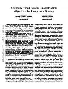
2.10 Expected significance of the SM Higgs boson signal in the ATLAS detector, as function of the Higgs mass, for an integrated luminosity of 30 pb −1 (left) and 100 pb−1 (right), for several decay channels The significance of a channel signal is defined as the ratio √SB between the signal S and the √ poissonian RMS of the corresponding background B. . . . . . . . . . . . . 25 3.1
3.2 3.3 3.4
3.5 3.6 3.7 3.8 3.9 3.10
3.11
3.12
3.13
Energy response of the EMC barrel prototype “Module 0” to 245 GeV electrons, from data taken during the year 2000 test–beam session (see text for details). . . . . . . . . . . . . . . . . . . . . . . . . . . . . . . . . . . . . Basics electrical model of a LAr cell with schematic readout chain and simplified calibration network. . . . . . . . . . . . . . . . . . . . . . . . . . . Complete schematics of an electrode Middle channel (a) and a reasonable simplification (b) . . . . . . . . . . . . . . . . . . . . . . . . . . . . . . . . . Picture of the mock–up during assembling. The two bottom gaps (3 rd and 4th in our numbering scheme) are complete, the 2 nd is open and the PP Strips and physics injection cables are visible. . . . . . . . . . . . . . . . . . Detail view of the mock–up system in its final layout; the accordion structure of the detector is visible. . . . . . . . . . . . . . . . . . . . . . . . . . . . . . View of the mock–up system in its final layout; the Faraday cage is visible on top of the detector model. . . . . . . . . . . . . . . . . . . . . . . . . . . Detail of one physics injector. . . . . . . . . . . . . . . . . . . . . . . . . . . Electric scheme of a “physics” injector (see text for details). . . . . . . . . . Simple schematics of a single LAr cell, as seen at the SB level (left), and simplified equivalent circuit (right). . . . . . . . . . . . . . . . . . . . . . . . Typical measurements of Cs and |Z| as functions of frequency for: (top) 4 gaps connected by the SB, and (bottom) single gaps nn. 1, 2, 3. The horizontal scale is logarithmic between 1 kHz and 100 MHz. In the bottom plot, the gap with anomalous trend (the “knee” at ≈ 15 kHz) is n. 2, where the physics injection is applied. . . . . . . . . . . . . . . . . . . . . . . . . . Simulation of the Strips and Back effect on C s and X = Im(Z) for: (top) 4 gaps connected by the SB, and (bottom) a single gap. The four curves describe the predicted trend for Middle only (solid), Middle+strips (dashed), Middle+back (dotted) and Middle+strips+back (dash-dotted). In the simulation, typical values for the detector parameters are used. . . . Simulation of the physics injector effect on C s and X = Im(Z) for: (top) 4 gaps connected by the SB, and (bottom) a single gap. The solid line is the trend without injector; the dashed line is the distortion due to the presence of the 4 kΩ - 100 pF physics injector (i.e. the one in use); the dotted line shows that decreasing R while keeping RC constant, increases the distortion. Measurements of the L,C values for single Middle gaps in the region η = 0.8 ÷ 1.2, corresponding to Middle cells 32÷47. Only connector 4 has one ground spring. . . . . . . . . . . . . . . . . . . . . . . . . . . . . . .
viii
28 29 32
34 35 36 37 38 39
41
42
43
45
List of Figures
3.14 Measurements of the L,C values for single Back gaps in the region η = 0.8 ÷ 1.2, corresponding to Middle cells 32÷47. Only connector 4 has one ground spring. Back cells numbering refer to the corresponding “even” Middle cell. . . . . . . . . . . . . . . . . . . . . . . . . . . . . . . . . . . . . 3.15 Measurements of the L,C values for Middle cells with SB, in the region η = 0.8 ÷ 1.2, corresponding to Middle cells 32÷47. Connector 4 has one ground spring. For connector 2 the measurement has been performed both with two and one ground spring (squares and stars, respectively). . . . . . . 3.16 Measurements of the L,C values for Back cells with SB, in the region η = 0.8 ÷ 1.2, corresponding to Middle cells 32÷47. Connector 4 has one ground spring. For connector 2 the measurement has been performed both with two and one ground spring (squares and stars, respectively). Back cells numbering refer to the corresponding “even” Middle cell. . . . . . . . . 3.17 Comparison of L measurements with and without summing board. . . . . . 3.18 Comparison of C measurements with and without summing board. . . . . . 3.19 Typical waveforms shaped at τsh = 15 ns, for a physics (black) and a calibration (red) signal, acquired on the same cell (middle 39 with two ground springs). . . . . . . . . . . . . . . . . . . . . . . . . . . . . . . . . . 3.20 Correlations among signal amplitudes and C, L cell parameters. Measurements are displayed both for two ground springs (solid circles) and one ground spring (open squares). . . . . . . . . . . . . . . . . . . . . . . . 3.21 Physics and calibration signal measured as a function of η. The plots on the left show the peaks of the output shaped signals for “physics”and “calibration” injection in cells 32÷39 from Middle sampling, and the ratio between the two. Solid circles (open squares) refer to measurements performed with two (one) ground springs per connector. The corresponding plots on the right show the relative deviation between the two ground configurations. . . . . . . . . . . . . . . . . . . . . . . . . . . . . . . . . . . 3.22 Signal amplitudes, measured as a function of η, for calibrated cluster obtained by injecting 80% of the signal in the central cell and 10% in each of the side cells. In the top figure, solid circles (open squares) refer to measurements performed with two (one) ground springs per connector. The bottom figure displays the relative variation between the two configurations. 3.23 Complete equivalent circuit describing six cells (four from Middle and two from Back sampling) sharing the same SB. The inductive ground return path and the cross capacitances between neighbor cells are shown. . . . . . 3.24 Simplified equivalent circuit used for the SPICE simulation, describing six cells (four from Middle and two from Back sampling) sharing the same SB. 3.25 Effective L values of mock–up cells 36÷39 of the Middle sampling and 36 and 38 of the Back sampling, versus their relative position on the SB itself (M36, B36, M37, M38, B38, M39). On top the values measured with and without the second ground connection, on bottom the difference between the two series. . . . . . . . . . . . . . . . . . . . . . . . . . . . . . . . . . . .
ix
46
47
48 50 51
52
53
54
56
58 59
61
List of Figures
3.26 Results of simulation using the detector SPICE model. The plots on the left show the peaks of the output shaped signals for “physics”and “calibration” injection in cells 32÷39 from Middle sampling, and the ratio between the two. The two series in each plot refer to two-grounds (solid circles) and one-ground (open squares) configurations on the second connector. The corresponding plots on the right show the relative deviation between the two ground configurations. . . . . . . . . . . . . . . . . . . . . . . . . . . . 3.27 Percentage variation on the output signal peaks (“physics”, “calibration”, ratio between the two) on cell 39 from Middle sampling, between the configuration with one and two ground connections. . . . . . . . . . . . . 3.28 Signal amplitudes, predicted for calibrated cluster obtained by injecting 80% of the signal in the central cell and 10% in each of the side cells. In the top figure, solid circles (open squares) refer to measurements performed with two (one) ground springs per connector. The bottom figure displays the relative variation between the two configurations. . . . . . . . . . . . . 3.29 Ground connection spring modification on the EMB readout electrodes: (top) missing–spring old layout; (bottom) new symmetric layout. . . . . . 4.1 4.2
4.3 4.4
4.5
4.6
First step of the “parabola” SR algorithm: a “raw” timing information is computed interpolating 3 sampled points of the signal. . . . . . . . . . . . Reference signal waveform after the shaping filter. In the “parabola” SR algorithm the shape of this reference waveform is assumed to be perfectly known. . . . . . . . . . . . . . . . . . . . . . . . . . . . . . . . . . . . . . . “Parabola” SR algorithm time (top) and amplitude (bottom) correction functions. . . . . . . . . . . . . . . . . . . . . . . . . . . . . . . . . . . . . “Parabola” SR algorithm performances, when the correction functions obtained from a mock–up calibration waveform are used to reconstruct the same sampled calibration signal: difference between “true” and reconstructed peak time, as a function of the signal delay value (left); percentage difference between “true” and reconstructed signal amplitude, as a function of the signal delay value (right). . . . . . . . . . . . . . . . . “Parabola” SR algorithm performances, when the correction functions obtained from a mock–up calibration waveform are used to reconstruct the sampled “ionization” signal from the same cell: difference between “true” and reconstructed peak time, as a function of the signal delay value (left); percentage difference between “true” and reconstructed signal amplitude, as a function of the signal delay value (right). . . . . . . . . . . . . . . . . “Parabola” SR algorithm performances, when the correction functions obtained from a mock–up calibration waveform are used to reconstruct the a sampled calibration signal from a different mock–up cell: difference between “true” and reconstructed peak time, as a function of the signal delay value (left); percentage difference between “true” and reconstructed signal amplitude, as a function of the signal delay value (right). . . . . . .
x
. 62
. 64
. 65 . 67
. 70
. 71 . 72
. 73
. 73
. 74
List of Figures
4.7
“Parabola” SR algorithm performances, when the correction functions obtained from a mock–up calibration waveform are used to reconstruct the sampled “ionization” signal from a different mock–up cell: difference between “true” and reconstructed peak time, as a function of the signal delay value (left); percentage difference between “true” and reconstructed signal amplitude, as a function of the signal delay value (right). . . . . . . . 74
4.8
Comparison between “parabola” (empty symbols) and “true” (full symbols, corresponding to a polynomial fit on the peak region) peak reconstruction of the mock–up signals, in case of multiple “physics” injection (cluster 10%/80%/10%): “ionization” vs. Middle cell position (top); calibration (middle); “ionization” over calibration ratio (bottom). Red symbols refer to the mock–up having only 1 ground returns connected in the second connector; black symbols to 2 ground returns connected. . . . . . . . . . . . 76
4.9
Injection–point correction on the mock–up M39 cell signals: measured “ionization” signal (black) and corrected “ionization”signal (red) comparison (top left); measured calibration signal (black) and corrected “ionization” signal (red) comparison (bottom left); measured “ionization” signal peak detail (top right); corrected “ionization” signal peak detail (middle right); measured calibration signal peak detail (bottom right). . . . 79
4.10 Mock–up “calibrated” signals with and without injection–point (LC) correction. . . . . . . �. . . . . . . . �. . . . . . . . . . . . . . . . . . . . . . . 80 - 2 gnds) in the second mock–up connector 4.11 Response variation (1 gnd 2 gnds (Middle cells M36÷M39) adding the second ground spring, with and without injection–point (LC) correction. . . . . . . . . . . . . . . . . . . . . 80 4.12 Energy response of the EMC barrel prototype “Module 0” cells line φ cell = 10 to 245 GeV electrons, from data taken during the year 2000 test– beam session: signal reconstructed and calibrated using the “parabola” SR method (full black dots) and with the OF4 SR method (open red squares).
82
5.1
Basic detector cell equivalent circuit, taking into account the resistive component r of the connection between the electrodes and the readout line. . . . . . . . . . . . . . . . . . . . . . . . . . . . . . . . . . . . . . . . . 88
5.2
Calibration waveform collected from the mock–up cell M32 (black). The extracted parameters and the relative transformed waveforms are shown: step–response transformation (red); cosine–response transformation (green); injection–point–correction residual oscillation (blue). The tail starting point is tmin = 600 ns for all the transformed waveform tail minimizations (see text for details). . . . . . . . . . . . . . . . . . . . . . . . 90 � 0 , f0 Surface (left) and contour (right) plot of the function log Q2 (τcali step ) 0 ,f 0 in the (τcali step ) parameters space. The “saw–teeth” structure around the minimum in left plot is not real, being due to the chosen number of points in the plot. . . . . . . . . . . . . . . . . . . . . . . . . . . . . . . . . . . . . 92
5.3
xi
List of Figures
5.4
5.5 5.6 5.7 5.8 5.9 5.10 5.11
5.12
5.13
5.14 5.15
5.16
5.17
5.18
Step–response minimization final parameters τ cali and fstep correlation with the signal tail starting point value t min . The region of tmin for which the final τcali and fstep values are stable is show. . . . . . . . . . . . . . . . . . Profile of Q2 (ω) (top) and Q02 (ω, τsh ) (bottom) as a function of the frequency ω. . . . . . . . . . . . . . . . . . . . . . . . . . . . . . . . . . . . Cosine–response minimization final parameter ω 0 correlation with the signal tail starting point value tmin . . . . . . . . . . . . . . . . . . . . . . . . . . � Surface (left) and contour (right) plot of the function log Q2 (τ00 , τr0 ) in the (τ00 ,τr0 ) parameters space. . . . . . . . . . . . . . . . . . . . . . . . . . Step–response minimization final parameters τ cali and fstep correlation with the signal tail starting point value t min . . . . . . . . . . . . . . . . . . . . Mock–up system setup, complemented with the full calibration–injection and signal–readout cables chains. . . . . . . . . . . . . . . . . . . . . . . . Calibration–injection and signal–readout cables, kept in a LN 2 dewar from the MB connection up to the warm–to–cold pin carrier. . . . . . . . . . . Mock–up calibration pulse injection circuit. The exponential decay time is obtained as τcali = (rint + Z)C, Z being the effective characteristic impedance of the calibration cables chain. . . . . . . . . . . . . . . . . . . Calibration pulse characteristic parameters f step (top) and τcali (bottom), as extracted by the step–response transformation algorithm applied to the mock–up Middle cells M32÷M39. Empty points refer to signals collected at warm, full points at cold. . . . . . . . . . . . . . . . . . . . . . . . . . . 1 as extracted by the cosine– Detector cell characteristic frequency ω 0 = √LC response transformation algorithm applied to the mock–up Middle cells M32÷M39 calibration signals: results and relative uncertainties (top); comparison with the direct measure (bottom) are shown. Empty points refer to signals collected at warm, full points at cold. . . . . . . . . . . . . 32–samples delay curves for different DAC values, acquired from the EMB module M10 Middle cell ηcell = 16, φcell = 1 in Medium gain. . . . . . . . Examples of the (5.42) fit on the DAC-dependent delay curves values at different time t. The values are taken from the delay curves shown in Figure 5.14 . . . . . . . . . . . . . . . . . . . . . . . . . . . . . . . . . . . Master Waveform values m(t) (top) and residual signal DAC0(t) (bottom), computed for the EMB module M10 Middle cell η cell = 16, φcell = 1 in Medium gain. . . . . . . . . . . . . . . . . . . . . . . . . . . . . . . . . . . Calibration pulse characteristic parameters f step (top) and τcali (middle) distributions, as extracted from the EM barrel production module M10 Middle cells 32–samples MW, in the region {η cell ∈ [16, 23], φcell ∈ [0, 7]}. The parameters correlation is shown in the bottom plot. . . . . . . . . . . Calibration pulse characteristic parameters f step (top) and τcali (middle) distributions, as extracted from the EM barrel production module P15 Middle cells 32–samples MW, in the region {η cell ∈ [0, 55], φcell ∈ [8, 15]}. The parameters correlation is shown in the bottom plot. . . . . . . . . . .
xii
. 94 . 97 . 98 . 100 . 101 . 102 . 103
. 104
. 105
. 106 . 108
. 109
. 110
. 112
. 113
List of Figures
5.19 Calibration pulse characteristic parameters f step (top) and τcali (bottom) as a function of the calibration board line number. The values refers to the Middle cells of Sector 4 of the EM barrel production module M10 (24 ≤ ηcell ≤ 31). The weighted means of each line groups of values are shown superimposed (black triangle) with the relative uncertainties. . . . . 114 5.20 Calibration pulse characteristic parameters f step (top) and τcali (bottom) as a function of the calibration board line number. The values refers to the Middle cells of Sector 1 of the EM barrel production module P15 (0 ≤ ηcell ≤ 7). The weighted means of each line groups of values are shown superimposed (black triangle) with the relative uncertainties. . . . . . . . . 115 5.21 EM barrel production module M10 Middle cells characteristic frequencies 1 values, as a function of ηcell for the different φcell lines. The values ω0 = √LC have been extracted from the 32–samples MW with the cosine–response algorithm. . . . . . . . . . . . . . . . . . . . . . . . . . . . . . . . . . . . . . 116 5.22 EM barrel production module P15 Middle cells characteristic frequencies 1 ω0 = √LC values, as a function of ηcell for the different φcell lines. The values have been extracted from the 32–samples MW with the cosine–response algorithm. . . . . . . . . . . . . . . . . . . . . . . . . . . . . . . . . . . . . . 116 5.23 EM barrel production module M10 Middle cells characteristic frequencies 1 values, as a function of φcell for the different ηcell positions, and ω0 = √LC averaged along η. The values have been extracted from the 32–samples MW with the cosine–response algorithm. . . . . . . . . . . . . . . . . . . . . . . 117 5.24 EM barrel production module P15 Middle cells characteristic frequencies 1 values, as a function of φcell for the different ηcell positions, and ω0 = √LC averaged along η. The values have been extracted from the 32–samples MW with the cosine–response algorithm. . . . . . . . . . . . . . . . . . . . . . . 117 5.25 EM barrel production module P15 Middle cells characteristic frequencies, as a function of ηcell for 8 different φ lines. The cosine–response extracted cold and with the ω ω0 values are compared with the direct measure ω meas OF4 values obtained through the OF4 fit procedure on the ionization pulses. . . 119 5.26 EM barrel production module P15 Middle cells characteristic frequencies, as a function of φcell for 8 different η lines. The cosine–response extracted cold and with the ω ω0 values are compared with the direct measure ω meas OF4 values obtained through the OF4 fit procedure on the ionization pulses. . . 121 5.27 Ionization pulse prediction computed for the EMB module M10 Middle cell ηcell = 18, φcell = 1, using the parameters {τcali , fstep , ω0 } extracted from the 32–samples calibration MW, and the nominal value of the drift time Td = 450 ns. The calibration MW (black), the ionization pulse prediction (red) and its derivative (blue) are shown on the full 800 ns interval (top), and in the restricted 125 ns zone of the positive lobe that is to be used for the OF coefficients computation (bottom). . . . . . . . . . . . . . . . . . . . 122
xiii
List of Figures
5.28 Ionization pulse predictions dependence on the T d drift time value (top). The pulse are computed for the EMB module M10 Middle cell η cell = 18, φcell = 1, using the parameters {τcali , fstep , ω0 } extracted from the 32– samples calibration MW, together with the nominal value of the drift time Td = 450 ns (black), or the test values T d1 = 430 ns (green) and Td2 = 470 ns (red). The percentage differences between the “nominal” and the two test predicted signal (middle), the zone of the signals peaks (bottom left) and of the signals tails (bottom right) are shown. . . . . . . . . . . . . . . . 123 5.29 OF coefficients sets computed for the EMB module M10 Middle cell ηcell = 18, φcell = 1 in the Medium gain region, using the ionization pulse prediction shown in Figure 5.27. The {a i } coefficients are shown in the left column of plots, as a function of the possible delay values. The {b i } coefficients are shown in the right column. . . . . . . . . . . . . . . . . . . . 124 5.30 Test of the OF SR iterative procedure. The peak of the “normalized” ionization waveform used to compute the coefficients is reconstructed using the OF SR system itself: number of iteration distribution (top left); number of iterations as a function of the delay value (top right); reconstructed peak distribution (middle left); reconstructed peak as a function of the delay value (middle right); reconstructed time distribution (bottom left); reconstructed time as a function of the delay value (bottom right). . . . . 125 5.31 Pictorial flowchart of a possible EMC calibration scenario at the LHC. . . . 126 6.1
Amount of material in term of radiation lengths X 0 (linear scale, left, and logarithmic scale, right) in the EMB calorimeter in the test-beam setup, as a function of η. The boundaries of the different samplings are shown. The active samplings (from bottom, Presampler, Strips, Middle and Back) are drawn in yellow, the non–active (“dead”) regions (before the Presampler and between the Presampler and the Strips) are drawn in red. . . . . . . . . 130
6.2
Mean longitudinal profile of the energy deposition in an electromagnetic shower generated by a E0 = 245 GeV electron in lead (ZPb = 82, EcPb ' 6.8 MeV). . . . . . . . . . . . . . . . . . . . . . . . . . . . . . . . . . . . . . . . 131
6.3
Mean energy loss in the EMB active samplings as a function of η, for an e.m. shower induced by a 245 GeV electron. From top to bottom, Presampler, Strips, Middle and Back. . . . . . . . . . . . . . . . . . . . . . . . . . . . . . 132
6.4
Mean energy loss in the EMB “dead” regions as a function of η, for an e.m. shower induced by a 245 GeV electron. Form top to bottom, mean energy deposited in the material in front of the Presampler, in the material between the Presampler and the Strips, and behind the Back. . . . . . . . . 133
6.5
Correlation between the energy lost in material in front of the EMB and the energy deposited in the Presampler, for an e.m. shower induced by a 245 GeV electron, according to the “toy” MC analysis. . . . . . . . . . . . . 134
xiv
List of Figures
6.6
6.7
6.8
6.9
6.10
6.11
6.12
6.13 6.14 6.15 6.16
6.17
7.1 7.2 7.3
EMB Energy recovering weights for an e.m. cascade induced by a 245 GeV electron, as a function function of η. The weights are computed with “toy” MonteCarlo (see text for details). Presampler weight (top); Strips weight (middle); Back weight (bottom). . . . . . . . . . . . . . . . . . . . . . . . Relative energy resolution σ[E tot ]/hEtot i as a function of the Presampler and Back weights (3-D plot and level curves). The weights for Strips and Middle layer are constrained to 1. . . . . . . . . . . . . . . . . . . . . . . . Example of typical distributions for the weights w i∗ , as obtained from the MC errors propagation. The values of µ i ’s and Cij ’s are from an EMB test beam run, and the weights normalization is w 3 = 1. . . . . . . . . . . . . . Weights evaluated for Presampler, Strips and Back (w1, w2, w4), as a hit , with Middle weight set to 1. In the left column all weights function of ηcell at several φhit cell are displayed together with their profile histogram. In the right column, different symbols and gray levels refer to different φ hit cell . . . . hit , Weights evaluated for Presampler and Back (w1, w4), as a function of η cell with Strips and Middle weights set to 1. In the left column all weights at several φhit cell are displayed together with their profile histogram. In the right column, different symbols and gray levels refer to different φ hit cell . . . . . . . Profile of weights evaluated for Presampler, Strips and Back (w1, w2, w4), hit . At each η hit the values with Middle weights set to 1, as a function of η cell cell hit are averaged over φcell . The fit is also displayed. . . . . . . . . . . . . . . Profile of weights evaluated for Presampler and Back (w1, w4), with Strips hit . At each η hit the values and Middle weights set to 1, as a function of η cell cell . The fit is also displayed. . . . . . . . . . . . . . . are averaged over φhit cell hit hit Total energy vs ηcell at several φcell (no weights applied). . . . . . . . . . . hit at several φhit (weights normalization: w Total energy vs ηcell ˜ 2+3 = 1). . . cell hit hit Total energy vs ηcell at several φcell (weights normalization: w ˜ 3 = 1). . . . Values of the σ[Etot ]/hEtot i energy resolution, mediated over φ hit cell , as a hit , for different weighting recipes. The weights evaluated cell function of ηcell by cell are used. . . . . . . . . . . . . . . . . . . . . . . . . . . . . . . . . . Values of the σ[Etot ]/hEtot i energy resolution, mediated over φ hit cell , as a hit function of ηcell , for different weighting recipes. The weights from the fits are used. . . . . . . . . . . . . . . . . . . . . . . . . . . . . . . . . . . . . .
. 136
. 138
. 140
. 142
. 143
. 144
. . . .
145 147 147 148
. 148
. 149
The EMB module test–beam cryostat on the movable table (left). An EMB production module is being inserted in the cryostat (right). . . . . . . . . . 153 CERN H8 beam line setup. Three different positions of the EMB module under test are shown. . . . . . . . . . . . . . . . . . . . . . . . . . . . . . . 153 Example of estimation of the η and φ coordinates of the impact point in a P15 EMB module test–beam run. The nominal position of the cryostat hit ) table was (ηcell = 18, φcell = 10). From to bottom: (ηcell Middle distribution; hit hit (ηcell )Strips distribution; ∆ηcell distribution (see text for details); (φ hit cell )Middle distribution. . . . . . . . . . . . . . . . . . . . . . . . . . . . . . . . . . . . 155
xv
List of Figures
7.4
Spectrum of the S3 ADC counts. The pedestal peak (black) is estimated with the random trigger events. The first peak of the distribution, compatible with a single MIP particle, is selected. . . . . . . . . . . . . . 7.5 Distributions of the residuals of the tracks interpolation fit in each of the four BC’s coordinates. The events which residuals are within 1 RMS from the mean of each distributions are selected. . . . . . . . . . . . . . . . . . 7.6 Correlations between the event η (φ) barycentre, as reconstructed in the Middle section, and the BC’s x (y) coordinate. The events for which the two values are compatible are selected. . . . . . . . . . . . . . . . . . . . . 7.7 Example of the final total energy distribution (top), and of the corresponding energy distributions in the four calorimeter layers, as obtained after the A6 selection (see text for details). The plots refers to electrons data from a run taken on the EMB production module P15 at ηcell = 18, φcell = 10 and Ebeam = 245 GeV. The gaussian fit to the peak is shown, and the labels Mean, Sigma are E peak and σgauss respectively. . . 7.8 Example of the cluster energy spectra for all EMC layers (from top to bottom, Presampler, Strips, Middle and Back): total (black) and above a given energy threshold (red) (see text for details). . . . . . . . . . . . . . . 7.9 Strips efficiency check algorithm summary. From top to bottom, in the exposed Strips region: total number of hits distribution; total energy distribution; mean energy deposit per events (two different estimation procedures); mean energy variation between adjacent Strips. . . . . . . . 7.10 EMB production modules M10 energy response uniformity evaluation, through the fit of the Epeak distribution. From top to bottom, full module after selections, FT0 and FT-1. . . . . . . . . . . . . . . . . . . . . . . . .
. 156
. 157
. 158
. 159
. 161
. 162
. 164
A.1 Charge collection scheme and current characteristic for a LAr ionization chamber, assuming uniform ionization over the gap. . . . . . . . . . . . . . 171 A.2 Simplified calibration board pulser circuit, showing the non-ideal nature of the inductance L in its resistive component r. . . . . . . . . . . . . . . . . . 174 A.3 Example of a mock–up calibration pulser circuit, showing the non-ideal nature of the capacitance C in its resistive component r. . . . . . . . . . . . 175 B.1 Optimization of the shaping time for LHC high and low luminosity running conditions. The amount of noise is plotted versus the peaking time of the shaper response to a delta function t p (∆). . . . . . . . . . . . . . . . . . . . 178
xvi
List of Tables 1.1 1.2 2.1 2.2 2.3 2.4
4.1 4.2 5.1 5.2
Main LHC parameters . . . . . . . . . . . . . . . . . . . . . . . . . . . . . . ATLAS calorimeters coverage and granularity (see Chapter 2 for details on the EMC structure.) . . . . . . . . . . . . . . . . . . . . . . . . . . . . . . . Main physical properties of the ATLAS EMC sampling calorimeter components († LAr density at T = 89.3 K). . . . . . . . . . . . . . . . . . Granularity and number of merged gaps per read-out cell for the different samplings. η is pseudo-rapidity and φ is azimuth. . . . . . . . . . . . . . . Properties of LAr related to the ionization signal generation. . . . . . . . Breakdown of the read-out line elements from the MB to the front-end crate baseline preamplifier. The impedance of the pigtail and the cold cable is matched with that of the preamplifier, which is 25 Ω for Middle and Back channels. The length of the pigtail and cold cable changes according to the distance of the MB from the feedthrough. . . . . . . . . . . . . . . . . . .
2 8
. 15 . 19 . 20
. 22
Mock–up uniformity (RMS %) with and without injection–point (LC) correction. . . . . . . . . . . . . . . . . . . . . . . . . . . . . . . . . . . . . . 78 Energy response uniformity (RMS %) of the EMC barrel prototype “Module 0” cells line φcell = 10.to 245 GeV electrons. . . . . . . . . . . . . . 83 Expected mock–up calibration decay time value, as a function of the the cables effective characteristic impedance Z. . . . . . . . . . . . . . . . . . . 104 Average τcali and fstep calibration parameters values, as extracted at warm and cold from the 8 mock–up Middle cells with the step–response transformation. . . . . . . . . . . . . . . . . . . . . . . . . . . . . . . . . . . 107
6.1
Uniformity of the energy Epeak obtained with different weighting recipes for the full EMB module P15 coverage (module), and in the FT0 (0 ≤ φ cell ≤ 7) and FT-1 (8 ≤ φcell ≤ 15) regions. . . . . . . . . . . . . . . . . . . . . . . . 146
7.1
Energy response uniformity of the EMB production modules M10, P15 . . . . . . . . . . . . . . . . . . . . . . . . . . . . . . . . . . Energy response uniformity of the EMB production modules M10, P15 in the FT0 region. . . . . . . . . . . . . . . . . . . . . . . . .
7.2
xvii
P13 and . . . . . . 165 P13 and . . . . . . 165
Chapter 1
The ATLAS detector at the LHC 1.1
The Large Hadron Collider
The Large Hadron Collider (LHC) [1] is presently under construction, and will start operation in 2007. It will be installed at CERN (European Center for the Nuclear Research, Geneva, Switzerland) in the existing 27 km tunnel formerly used for LEP (Large Electron– Positron collider, Figure 1.1). LHC will provide 14 TeV center–of–mass energy proton– proton (pp) collisions, at a luminosity up to 10 34 cm−2 s−1 with a bunch crossing frequency of 40 MHz. LHC will be also capable to produce heavy ions (e.g. Pb–Pb) collisions. Four large–scale experiments will operate at LHC. ATLAS and CMS are general– purpose experiments, with a wide physics program; LHCb is devoted to the physics of Bhadrons and to the study of the CP violation; ALICE is a dedicated heavy–ions experiment, that will study the behavior of the nuclear matter at very high energies and densities. The LHC physics program is broad and ambitious. The strong physics motivations that support the building of such an unprecedented collider machine can be briefly summarized as follows: • Search for the Standard Model (SM) Higgs boson [13], that is predicted to be the responsible of the origin of the particle masses through the mechanism of spontaneous breaking of the electro–weak symmetry. • Look for the physics beyond the SM, that for several reasons cannot be expected to be the ultimate theory of particles interactions [14, 15, 16]. • Perform precision measurements of the properties of the known particles, in order both to refine the present values and to search signals of new physics in unexpected deviations from the SM predictions [17].
1.1.1
Proton–proton collisions characteristics
Two operation phases are foreseen for LHC: in the first years the accelerator will provide a instantaneous luminosity of L ' 10 33 cm−2 s−1 (“low” luminosity phase); the nominal 1
Chapter 1 – The ATLAS detector at the LHC
Figure 1.1: Layout of CERN LEP tunnel, including the future LHC infrastructures.
LHC parameter beam energy beam energy at injection nominal luminosity luminosity life time beam life time number of bunches proton (p) per bunch bunch spacing p current intensity beam total energy energy loss per tour
nominal value 7 TeV 450 GeV 1034 cm−2 cm−1 10 hours 22 hours 2835 1011 25 ns (7.5 m) 0.54 A 334 MJ 6.7 keV
Table 1.1: Main LHC parameters
2
1.1 – The Large Hadron Collider
luminosity L ' 1034 cm−2 s−1 will be reached later (“high” luminosity phase). The nominal pp luminosity and center–of–mass will allow searches for new particles up to masses of ∼ 5 TeV. Details on the LHC machine parameters can be found in Table 1.1 [1]. In one year (1 “year” run time ' 107 s) of running at high luminosity LHC will provide an integrated luminosity of: Z Ldt ' 100 fb−1 (1.1) L= 107 s
√ tot ∼ 80 mb. The LHC event rate The total inelastic pp cross–section at s = 14 TeV is σpp R at high luminosity is then expected to be: tot R = σpp × L = 80mb × 1034 cm−2 s−1 ' 109 s−1
(1.2)
These events belong to two different classes: • “minimum bias events”: they comes from long–range interactions of the incoming protons, in which the momentum transfer is small (“soft” collisions). They represent the majority of the pp collisions, their effective total cross section being tot σm.b. ∼ 70 mb. The study of these interactions is not foreseen in the LHC experiments physics programs. The final state products of these interactions have small transverse momentum relative to the beam line (hp T i ' 500 MeV): most of them escape down the beam pipe. The produced particles with p T high enough to enter the active region of the detectors give rise to the pile–up phenomenon (Section 1.1.2). • “hard scattering events”: they come from short–range interactions of the incoming protons. In these cases the head–on collisions between the partons constituting the protons are characterized by an high momentum transfer. Particles in the final state are produced at high angles with respect to the beam line (high p T ), and massive particles can be created. These are the physics events that will be recorded and studied; they are “rare” with respect to the soft interactions [5].
1.1.2
LHC experimental challenges
The LHC experimental framework will be highly demanding. The LHC detectors have to face severe constrains, most of them related to the machine bunch crossing frequency (response speed), luminosity (pile–up, radiation level), and to the physics of the pp collisions (background rejection capability). Pile–up The LHC protons are grouped in bunches of ∼ 10 11 , colliding at each interaction point every 25 ns. According to the interaction rate at high luminosity (equation 1.2), on average 25 minimum bias events (soft interactions) will occur simultaneously every bunch crossing.
3
Chapter 1 – The ATLAS detector at the LHC
These interactions will produce ∼ 700 charged particles in the detectors pseudorapidity 1 region |η| < 2.5. Each time a high pT event is produced, ∼25 additional soft events will overlap to the interesting one (pile–up). The pile–up is one of the most difficult challenges for the LHC detectors design. In order to minimize the pile–up impact on the physics events detection, the LHC sub-detector use different techniques. In general, their response must be fast, in order to avoid to integrate over more that one or two bunch crossings. This implies also a fast readout electronics. In addition, a fine granularity would minimize the probability that the pile–up particles cross the same region of the detector as the interesting object. In case the sub–detectors response cannot be sped up to 25–50 ns, such in the case of the ATLAS LAr EMC, different technique of signal shaping and reconstruction has been developed, in order to be able to treat the pile–up events as a kind of noise that superimposes to the interesting physics signal (see Chapter 2 and Appendix B). Radiation levels The high flux of particles coming from the pp collisions represents an unavoidable source of radiation for the LHC detectors, that for this reason must be radiation resistant. The radiation level to stand will be different according to the sub–detector position with respect to the interaction point As an example, in the forward calorimeters the particles flux, integrated over 10 years of operations, will amount up to 10 17 neutrons cm−2 and up to 107 Gy of absorbed energy. The ATLAS electromagnetic calorimeter, to which this work is dedicated, will receive less than 1013 neutrons cm−2 and ∼200 Gy in 10 years at high luminosity in the worst place of the electronics [3]. QCD background Being LHC an hadronic collider, the rate of high p T events is dominated by QCD jets production, that is a strong process and has a large cross section. On the other hand, the most interesting physics processes are rare: indeed there is no hope to detect a rare object (e.g. the SM Higgs boson) decay into jets. Because of this reason, the main LHC physics searches will be conducted looking for rare decay channels [5]. The detectors performances must be optimized both for the background rejection and for dealing with such rare–channels detection.
1.2
The ATLAS Detector
ATLAS [2] (A Toroidal LHC ApparatuS, Figure 1.2) is one of the two LHC general– purpose detector presently under construction. It is designed to be a typical collider multi–purpose detector, with a large discovery potential for new physics such as Higgs bosons and SuperSymmetric particles (SUSY) [5]. 1
The pseudorapidity is defined as η = − log(tan( 2θ )), where θ is the polar angle referred to beam direction at the detector interaction point.
4
1.2 – The ATLAS Detector
Figure 1.2: Tridimensional cut–away of the full ATLAS detector.
Among the LHC general–purpose experiments, different design philosophies have been adopted by the collaborations. The ATLAS detector uses a very large air–core toroid for the muon spectrometer. The electromagnetic calorimetry is based on the lead–liquid Argon sampling technology. The hadronic calorimetry uses an iron–scintillator detector in the barrel, and again the liquid–Argon technology in the end–caps. Integrated in the barrel electromagnetic cryostat, a superconducting coil solenoid provides a 2 T magnetic field for the inner detector. The inner tracking system is based on semiconductor detectors in the innermost part, and on straw tubes in the outer one. The philosophy that lyes underneath the ATLAS sub–detectors design can be summarized as follows: • very good electromagnetic calorimetry, for e and γ identification and measurement; maximal ermeticity of the full calorimetry system for very accurate missing measurements and jets identification; transverse momentum pmiss T • efficient tracking system at high luminosity, for high p T leptons measurements, and full event reconstruction capability at low luminosity. • high–precision muon spectrometer, with the capability to perform accurate measures at the highest luminosity in stand–alone mode (i.e. without seeds from the inner tracking system).
5
Chapter 1 – The ATLAS detector at the LHC
1.2.1
Inner Detector
The Inner Detector (ID) system [6] covers the acceptance range |η| < 2.5, matching that of the rest of the ATLAS sub–detectors for precision physics [5]. The ID, thanks to the tracks bending provided by the solenoid magnet (Section 1.2.4), is responsible to measure the momentum of the charged particles coming from the interaction point. Together with the electromagnetic calorimeter, it provides the identification of electrons and photons. At low luminosity it allows the secondary vertex reconstruction in case of decay of τ leptons or b–flavored hadrons. Barrel SCT Forward SCT
TRT Pixel Detectors Figure 1.3: Tridimensional cut–away view of the ATLAS inner detector system.
The ATLAS ID tracking system (Figure 1.3) is composed of three different sub– detectors layers: • The Pixel Detector (PD) [7] is located in a range between 4 and 22 cm from the beam line. It is based on the detection of the charge deposited by the crossing ionizing particle in a finely segmented silicon detector. The PD is composed of 3 different layers, located at increasing radii and designed to give 3 space points per track. The first pixel layer (“b–layer”), located at 4 cm from the interaction point, gives a substantial contribution to the secondary vertex measurements, and is designed to be replaceable due to the very hostile environment. At |η < 0.25| the pixels transverse impact parameter resolution can be parametrized as σ(d 0 ) = (11 + 60/pT ) µm when the dedicated b–physics layer is present, the longitudinal impact parameter resolution as σ(z0 ) = (70 + 100/pT ) µm [7]. • The SemiConductor Tracker (SCT) system follows the PD up to 56 cm from the beam line, and is again based on the silicon technique. The barrel SCT uses 4 layers of micro-strips to provide precision points in space. • the Transition Radiation Tracker (TRT) is based on the use of straw tubes that can operate at very high rate. The use of Xe gas provides the TRT with electrons identification capability, that is exploited by the detection of the transition–radiation photons coming from polypropylene radiators located between the straws.
6
1.2 – The ATLAS Detector
EM Accordion Calorimeters
Hadronic Tile Calorimeters
Forward LAr Calorimeters Hadronic LAr End Cap Calorimeters Figure 1.4: Tridimensional cut–away view of the ATLAS calorimetry system.
1.2.2
Calorimetry
A crucial role in the LHC experiments will be played by the calorimeters. They will be responsible to measure photons, electrons, isolated hadrons and jets, as well as the missing transverse energy. Furthermore, the calorimetric informations will be used by the first level trigger to discriminate if an occurring physics event is interesting or is to be rejected (Section 1.2.5). In association with the ID, the calorimetry system will be used to identify electrons and photons. Because of the LHC operating conditions, fast detectors response and fine granularity are required to minimize the pile–up effect, together with high radiation resistance. Using different techniques the ATLAS calorimeters cover the range |η < 5| (Figure 1.4). The coverage and granularity of the ATLAS calorimeters are listed in Table 1.2. The electromagnetic calorimeter (EMC) is a lead–liquid Argon (LAr) sampling calorimeter [3], consisting in one barrel and two end–caps detectors covering the region |η| < 3.2. Being the main subject of this work, Chapter 2 is dedicated to a detailed discussion of its main characteristics. The tile hadronic calorimeter (TILECAL) [8] consists of one barrel and two extended–barrel cylinders that cover the region |η| < 1.7. The detector is based on a sampling technique with plastic scintillator planes (“tiles”). The tiles are placed in planes perpendicular to the beam axis, and embedded in an absorbing iron matrix; the scintillation signals are read through wavelength shifting optical fibers. The TILECAL is
7
Chapter 1 – The ATLAS detector at the LHC
calorimetry system Presampler electromagnetic barrel
η coverage |η| < 1.8 |η| < 1.4
electromagnetic end-caps hadronic barrels
1.4 < |η| < 3.2 |η| < 1.7
hadronic end-caps
1.5 < |η| < 2.5 2.5 < |η| < 3.2 3.2 < |η| < 4.9
forward calorimeter
∆η × ∆φ granularity 0.025×0.1 0.003×0.1 0.025×0.025 0.05×0.035 as in the barrel for 0.01×0.1 0.02×0.1 0.01×0.1 0.02×0.2 ∼0.02×0.2
sampling (S1) (S2) (S3) |η < 1.8| (S1, S2) (S3) (S1, S2, S3) (S1, S2, S3)
Table 1.2: ATLAS calorimeters coverage and granularity (see Chapter 2 for details on the EMC structure.)
longitudinally segmented in three layers. The relative energy resolution is required to be σE √ 50% ⊕ 3%, mainly driven by the jets measurements accuracy. E = E(GeV)
Two hadronic end–caps calorimeters (HEC) complement the hadronic calorimetry in the region 1.5 < |η| < 3.2. They are based on the LAr technology because of the high radiation level to be stand [3]. The HEC’s are housed in the same electromagnetic end–caps cryostats (see Chapter 2) with the forward calorimeters (FCAL). These detectors cover the region 3.1 < |η| < 4.9, thus assuring a continuity of coverage even in a region where the radiation level is really high. For this reason they are again based on the LAr technology [3].
1.2.3
Muon spectrometer
The ATLAS detector is equipped with a high–resolution muon spectrometer [9], with momentum measurement and stand–alone triggering capability over a wide range of transverse momentum, pseudorapidity and azimuthal angle. The magnetic deflection of the muon tracks is induced by the air–core toroid magnets system (see Section 1.2.4). The muon spectrometer system is composed by two different types of detectors (Figure 1.5): the Monitor Drift Tubes (MDT) perform a precision measurements of the tracks coordinates in the principal direction of the magnetic field over most of the pseudorapidity range; the Cathode Strips Chambers (CSC) are used in the first station of the end–cap region and for pseudorapidity |η| > 2 to sustain the demanding rate and background conditions. T ' 1% for transverse The required muon transverse momentum resolution is ∆p pT T momentum pT > 6 GeV/c, and ∆p pT ' 10% for transverse momentum p T > 1 TeV/c. The expected muon identification efficiency is 90% at p T > 6 GeV/c. The muon spectrometer is also equipped with trigger chambers (Resistive Plate Chambers (RPC) in the barrel region |η| < 1.4, and Thin Gap Chambers (TGC) in
8
1.2 – The ATLAS Detector
Resistive Plate Chambers
Cathode Strip Chambers
Thin Gap Chambers
Monitored Drift Tube Chambers
Figure 1.5: Tridimensional cut–away view of the ATLAS muon spectrometer system.
the end–cap regions), used as threshold detectors for the bunch crossing identification. These chambers have a time resolution better than the 25 ns LHC bunch spacing, and are used to trigger the acquisition of events with a definite p T cut–off.
1.2.4
Magnets system
The ATLAS detector system is provided with two different kind of magnetic fields [10] (Figure 1.6). A central superconducting–coil solenoid provides a 2 T field to the ID in the region |η| < 1.5. It bends the charged particles that cross the tracking system, allowing the momentum measure. The central solenoid is housed between the ID and the EMC, in the EM barrel cryostat. It represents indeed an additional amount of material in front of the EMC, that can in principle degrade the EMC performance (see Chapter 2 and 6). The muon spectrometer is equipped with a system of three large superconducting air–core toroids (one barrel and two end–caps, Figure 1.6), that produce the magnetic deflection of the muons tracks. The large barrel toroid (∼20 m diameter), consisting in eight coils that surround the hadronic calorimeter, provides the magnetic bending in the region |η| < 1. In the 1.4 < |η| < 2.7 region the muon tracks are bent by the two smaller end–caps toroid, while in the 1 < |η| < 1.4 range the magnetic bending is assured by a combination of the barrel and end–caps toroids fields.
9
Chapter 1 – The ATLAS detector at the LHC
Figure 1.6: Tridimensional pictorial view of the ATLAS magnets coils system. The central cylindrical coil of the superconducting solenoid is visible, surrounded by the air–core barrel and end–caps toroids coils.
1.2.5
Trigger and DAQ
The LHC experiments need a trigger system able to reduce the huge amount of data coming from the detectors because of the high interaction rate. Only 1 event over ∼ 10 7 is to be selected and recorded for the off–line analysis. The ATLAS trigger system is organized around three decision levels, and on the concept of the “Region Of Interest” (ROI). Since it is impossible to take a decision about the event quality in the 25 ns bunch spacing, all the data from the detectors are stored in pipeline memories, while the information from the calorimetry system and from the muon spectrometer are used to make a first selection (Level 1 trigger (LV1) [11], Figure 1.7 left), and, in case the event seems promising, to define in which regions of the detector the event has left its main signatures (ROI, Figure 1.7 right). The LV1 computation is performed by dedicated hardware processors, and is expected to reduce the event rate from 40 MHz to 100 kHz. The latency time of the LV1 is ∼2 µs. The Level 2 trigger (LV2)[12] refines in the ROI’s only the raw analysis of the detector informations performed the LV1. The latency time of the LV2 is ∼10 ms; it is expected to reduce the event rate from 100 kHz to 1 kHz. Finally, the events selected by the LV2 are analysed by the Level 3 trigger (“event filter”) (LV3/EF) [12]. It that reconstructs the selected event using the informations coming from the full ATLAS detector, as retrieved from the memory pipelines. The LV3/EF output rate is expected to be between 10 Hz and 100 Hz. The scheme of the DAQ pipelines architecture along with the event selection stages is illustrated in Figure 1.8.
10
1.2 – The ATLAS Detector
Calorimeters
Muon Detectors
Calorimeter Trigger Processor ET miss
Muon Trigger Processor µ
e/γ
jet
Subtrigger information
“ROI” data
Central Trigger Processor
Region of Interest Builder
Timing, Trigger and Control distribution
Front-End Systems
Level-2 Trigger
Figure 1.7: Operating principles of the ATLAS Level 1 trigger: informations flow from the ATLAS main sub-detectors (left); “Regions Of Interest” (ROI’s) (right);
Interaction rate ~1 GHz Bunch crossing rate 40 MHz
CALO
MUON TRACKING
Pipeline memories
LEVEL 1 TRIGGER < 75 (100) kHz
Derandomizers Readout drivers (RODs)
Regions of Interest LEVEL 2 TRIGGER
Readout buffers (ROBs)
~ 1 kHz Event builder Full-event buffers and processor sub-farms
EVENT FILTER ~ 100 Hz
Data recording
Figure 1.8: Scheme of the ATLAS DAQ pipelines, along with the trigger levels.
11
Chapter 1 – The ATLAS detector at the LHC
1.2.6
A short outline of the ATLAS physics program
The ATLAS experiment has been optimized for the detection of a large variety of physics signatures, accessible at the high luminosity and center–of–mass energy of the LHC pp collisions. We propose here a very short outline of the ATLAS physics program. It is beyond the scope of this work a detailed discussion of the full ATLAS physics potential; an exhaustive documentation of all the relevant ATLAS physics studies can be found in [5]. Being the optimization of the EMC performances the main subject of this work, a summary of the physics requirements on this detector is proposed in Section 2.4, along with a brief discussion of the physics study that will mostly take advantage of the electromagnetic calorimetry informations. The main goals of the ATLAS physics program follow the LHC construction motivations. The main focus of the experiment is the investigation of the nature of the electro–weak symmetry breaking, and therefore the search for the Higgs bosons. Thanks to the sensibility of the different ATLAS sub–detectors to different decay channels, the Higgs bosons could be discovered over a wide mass range (see Section 2.4 and Figure 2.10). The complementary aim of the ATLAS experiment is to find signatures of physics beyond the SM. Targets of this search are the particles predicted by SUSY or Technicolor theories, as well as new gauge bosons and composite quarks and leptons up to mass ∼5 TeV. Besides the discovery potential, the ATLAS experiment has also a large capability of performing precision measurements on the SM particles properties (e.g. W mass, t mass, triple gauge coupling). As an example, the error on the W mass is expected to be 0.02 GeV in ATLAS, i.e. better than that achieved in previous experiments (∼0.02 GeV). An important part of the ATLAS physics program is constituted by the b–physics studies. A proof of direct CP violation can be established thanks to the achievable precision on the sin 2β and sin α parameters of ±0.01 and ± 0.05 respectively.
12
Chapter 2
The liquid Argon electromagnetic calorimeter The LHC experimental framework will be highly demanding, imposing severe constraints on the detectors in terms of spatial coverage, response speed, radiation tolerance, background rejection capability, noise handling and time stability. For what concerns the electromagnetic calorimeter (EMC), the ATLAS collaboration has chosen a lead–liquid Argon (LAr) sampling calorimeter with an accordion geometry. This geometric feature guarantees a full azimuthal coverage without cracks and dead zones. The LAr used as ionizing medium is intrinsically radiation tolerant. The fast electronic readout can handle the LHC signal rate, and the noise contribution to the total energy, coming both from electronics and from pile–up due to minimum–bias events, is minimized using an optimized bipolar shaper and a digital filtering signal reconstruction technique (Appendix B). The whole system can be calibrated cell by cell with an embedded electronic system, and its sensitivity does not degrade in time. A detailed description of the ATLAS LAr EMC system is found in [3]. The calorimeter performances has been deeply investigated in [4], their impact on the ATLAS physics program is discussed in [5]. In this chapter the major characteristics of the system are briefly reviewed: a particular attention is given to those directly related to this work.
2.1
General description
The ATLAS EMC is a sampling calorimeter, consisting in a sequence of active layers, in charge of recording the particles signal, and passive layers, that are the major responsibles of the shower developing, and absorb the greater part of the shower energy. In the ATLAS EMC the active medium is LAr, kept at a temperature of ∼ 89 K in a cryostat (Figure 2.1), while the passive medium consists in lead absorbers, covered in stainless steel for mechanical reasons. The main properties of the EMC active and passive components are review in Table 2.1 and 2.3. The LAr gaps between consecutive absorbers are instrumented with electrodes, which are built as sandwiches of three copper planes separated by two kapton insulator layers
13
Chapter 2 – The liquid Argon electromagnetic calorimeter
Figure 2.1: View of one half on the EMB cryostat.
14
2.1 – General description
atomic number atomic weight density† radiation length radiation lento Moliere radius Moliere radius Critical energy
Z A ρ (g cm−3 ) X0 ' 180 ZA2 (g cm−2 ) X0 (cm) −2 RM ' 7 A Z (g cm ) RM (cm) Ec ' 560 Z (MeV)
LAr 18 39.948 1.381 19.55 14.2 13.9 10.1 30.5
Pb 82 207.2 11.35 6.37 0.56 17.7 1.55 6.82
Table 2.1: Main physical properties of the ATLAS EMC sampling calorimeter components († LAr density at T = 89.3 K).
47 cm
readout electrode
P
liq
on arg uid
uid
arg
stainless steel glue lead
liq
on
ga
ga
p
outer copper layer
p
(~2
mm
)
outer copper layer inner copper layer kapton
absorber
HV
HV
Figure 2.2: Detailed view of a EMB LAr gap section.
15
Chapter 2 – The liquid Argon electromagnetic calorimeter
1.9 LAr
40.1
25
Kapton
2.2
o.1 inox 0.1 inox 1.8 Lead
Figure 2.3: Sketch of the ATLAS LAr electromagnetic calorimeter accordion structure (left); GEANT simulation of an electromagnetic shower developing in the EMC.
(Figure 2.2). The two external copper planes distribute the high voltage (HV) across the LAr gap, thus forcing the drift of electrons and ions produced by the ionizing shower particles; the electrode inner plane records the ionization current by capacitive coupling. The absorbers provide the ground reference both for the HV distribution and for the ionization current. The electrodes are kept in place by means of honeycomb spacers. Both electrodes and absorbers have an accordion geometry (Fig. 2.3, [22]): the accordion shape makes the detector continuous, offering a full azimuthal acceptance 0 < φ < 2π without dead zones. The EMC pseudorapidity coverage is |η| < 3.2 (see Section 2.2 for details). The region |η| < 2.5 is designed to be used for precision physics measurements [5]. The EMC sampling frequency fsamp computes how many times the developing shower is sampled in a radiation lent X0 : fsamp (η) =
X0 a(η) + p(η)
(2.1)
a(η) is the depth of a single active LAr gap, p(η) is the depth of the passive absorber, as seen by a crossing particle at a given η position. The calorimeter effective radiation Lent is X0 ' X0Pb , being X0Pb � X0LAr (Table 2.1). At η = 0 a = 0.015 X0 and p = 0.28 X0 , the sampling frequency is fsamp (η = 0) = 3.4. For geometrical reasons the sampling frequency decreases at large |η|, thus leading to an increase of the fluctuations in the number of secondary electron tracks in the LAr gaps, and therefore reducing the detector intrinsic resolution. This effect is compensated by a reduction of the lead thickness in the absorbers in the region |η| > 0.8 [3]. The EMC sampling fraction F measures the ratio between the energy deposited by Minimum Ionizing Particle (MIP) in the active medium, and the total energy lost in the
16
2.2 – Segmentation and granularity
full detector (LAr gaps + passive lead absorbers). In the ATLAS EMC [3]: F =
∆ELAr ' 19% ∆ELAr + ∆EPb
(2.2)
Being a sampling calorimeter, the detector intrinsic energy resolution is dominated by the poissonian fluctuations of the number N of the shower secondary electron tracks that cross the active LAr gaps: √ ∆E a N =√ = E intr N E
(2.3)
being N proportional to the incoming particle energy √ E, at least at first order. The sampling term a is expected to be of order of 10% GeV [3]. There are other effects that contributes to deteriorate the energy resolution of the EMC, that can in general be expressed as: a b ∆E = √ ⊕ ⊕c E E E
(2.4)
The term b takes into account the fluctuation on the energy measurements due to noise from the readout electronics and the pile–up events (see Appendix A). The electronics readout system has been designed in order to keep b ' 400 MeV. The constant term c includes all the effects related to the detector imperfections (active medium impurity, absorbers or gap thickness non–uniformity, . . . ) and to the quality of the calibration (see Section 7.1). It is the most critical parameter in terms of high energy performance of the detector.
2.2
Segmentation and granularity
The EMC is divided in two parts: the barrel (EMB), that covers a pseudorapidity range |η| < 1.4, and the end-cap (EMEC), located in the region 1.4 < |η| < 3.2. Each part covers a full azimuth acceptance 0 < φ < 2π. The detector is segmented in longitudinal samplings, that for example in the barrel are defined as (Fig. 2.4): • S1 (“Front” or “Strips”), made of narrow strips to perform position measurement and γ − π 0 separation, has a 6 X0 depth. It has a granularity ∆η × ∆φ ' 0.003×0.1. • S2 (“Middle”), made of square towers with a depth of 16 to 18 X 0 , collects most of the e/γ shower energy. It has a granularity ∆η × ∆φ ' 0.025×0.025. • S3, (“Back”), with a depth of 2 to 12 X 0 , is used to sample high energy showers and helps to separate hadronic to electromagnetic particle. It has a granularity ∆η × ∆φ ' 0.05×0.025. 17
Chapter 2 – The liquid Argon electromagnetic calorimeter
Towers in Sampling 3 ∆ϕ×∆η = 0.0245×0.05 Trigge
r Towe ∆η = 0 r .1
2X0
47
0m m
η=0
16X0 Trigge Tow r ∆ϕ = 0er .0982
m
m
4.3X0
15
00
1.7X0 ∆ϕ=0.0 245x 36.8m 4 mx =147.3 4 mm
Square towers in Sampling 2 ∆ϕ = 0
.0245
ϕ 37.5m
∆η = 0
.025
m/8 = 4 ∆η = 0 .69 mm .0031 Strip towers in Sampling 1
η
Figure 2.4: Sampling segmentation and granularity of the EMB.
In the region |η| < 1.8, Presampler detectors located in front of the EMC are used to correct for the energy lost in the material upstream (mainly the inner tracking system, the LAr cryostat and the solenoid coil). Projectivity and granularity in pseudorapidity η are obtained by properly etching the readout electrodes (Figure 2.5). For construction reasons, two types of electrodes are used: type A for 0 < |η| < 0.8 and type B for 0.8 < |η| < 1.4. Along the azimuthal angle φ the projective geometry imposes that the accordion angles of absorbers and electrodes become more acute at increasing radius, thus ensuring a constant LAr gap and sampling fraction. Granularity in φ is defined by grouping together a proper number of electrodes: the signals coming from electrodes contiguous in azimuth are merged by the “summing boards” (SB) to form the read–out cells (Figure 2.6). The number of gaps merged for each sampling, and the relative granularity in η × φ, are displayed for the EMB in Table 2.2.
Figure 2.5: View of the signal layer of the EMB readout electrodes A and B. The readout pads for the different samplings are shown.
18
2.2 – Segmentation and granularity
Figure 2.6: View of the front side of the accordion, showing the placement of the Strips summing boards (SB) and the mother board (MB). Similar connection for the Middle and Back sampling are present on the back side of the accordion.
Sampling Strips Middle Back
Number of merged gaps 16 4 4
Granularity (∆η × ∆φ) w.r.t. Middle 0.00375×0.1 1/8 × 4 0.025×0.025 1×1 0.050×0.025 2×1
Table 2.2: Granularity and number of merged gaps per read-out cell for the different samplings. η is pseudo-rapidity and φ is azimuth.
19
Chapter 2 – The liquid Argon electromagnetic calorimeter
LAr property normal boiling point (bp) (K) h∆EMIP (1cm)i (MeV) W -value (1 MeV electrons) (eV/ion–pair) electron mobility at bp (m2 V−1 s−1 ) ion mobility at bp (m2 V−1 s−1 ) dielectric constant �r
value 87.27 2.1 23.3 0.048 0.016·105 1.6
Table 2.3: Properties of LAr related to the ionization signal generation.
The angular position, usually defined by the pseudorapidity η and the azimuthal angle φ (in radians), is often indicated by the coordinates η cell , φcell , which are expressed in units of Middle layer cells. Therefore, the Middle cell at lowest η, φ in the module is labeled by ηcell = 0, φcell = 0, and since the granularity of this layer is ∆η × ∆φ = 0.025 × 0.025, the following general relation holds: �
η = (ηcell + 0.5) × 0.025 φ = (φcell + 0.5) × 0.025
(2.5)
In the present work, references to Middle cells will often have the form Mx, where x = η cell runs from 0 to 54 in the EMB (e.g. the first eight cells in electrodes B are named M32÷M39). Each pair of Middle cells share the same Back cell, therefore referencing will be based on the number of the associated even Middle cell (e.g. B32 refers to the Back cell shared by M32 and M33).
2.3
Readout system
2.3.1
Signal generation
After the passage of the ionizing particles produced in the electromagnetic shower, electrons and positive ions drift along the electric field. Because of mobility reasons (see Table 2.3) the fast signal is produced by the electrons drift. The resulting current has a triangular waveform [29] with a sub–nanoseconds rise time followed by a linear decay with the duration of the electron drift time T d (Figure 2.7). In the EMB the drift time is Td ' 450 ns for a gap thickness g = 2.1 mm and 2000 V HV bias. The deposited charge is collected by the readout electrodes, the absorbers provide the ground reference. The ionization electron signal generation is detailed in Appendix A. The ionization current peak is proportional to the deposited energy: the energy-tocurrent nominal sensitivity for the EMB is 2.7 µA/GeV in the 0 < |η| < 0.8 region, and 3.1 µA/GeV in the 0.8 < |η| < 1.4 region [3]. The dynamic range is expected to range between 50 MeV (electronics noise level) and 3 TeV (energy scale of the electrons that could come from the Z 0 and W 0 decays [5]).
20
2.3 – Readout system
Figure 2.7: Ionization signal with amplified–and–shaped signal superimposed. Sampling points are shown.
2.3.2
Ground reference
Each SB located behind1 the EMB covers 4×4 Middle cells and 2×4 Back cells, corresponding to an acceptance ∆η × ∆φ = 0.1 × 0.1. For each φ row, the signal out of the SB is arranged in the pattern M-B-M-M-B-M, where M and B denote Middle and Back cells (Figure 2.8). Each signal line has its own ground reference; the ground plane of the SB is connected to the absorbers through paths located on the electrodes that end with springs (“ground springs”) touching the absorbers. Each SB is designed to take the ground reference from the two sides; however, on the first electrodes design, the “odd” read-out connectors located near the HV connectors had only one ground return path to the absorber, located on the low-η side. The consequence of this type of grounding on the detector performances is detailed studied in Chapter 3.
2.3.3
Readout lines
The SB’s are grouped in 2 × 2 patterns by the “mother-boards” (MB), therefore each MB covers an acceptance ∆η×∆φ = 0.2×0.2, corresponding to 8×8 Middle cells and 4×8 Back cells. An analogous structure on the detector front collects and routes the signals from the Strips. A complex chain of readout lines is in charge to carry the signals from the MB to the readout electronics, that is located in warm crates outside the EMC cryostat. The readout line elements are listed in Table 2.4, from the MB connector to the baseplane of the crate in which the readout electronics cards are plugged. The characteristic impedance of the readout cables chain is optimized for the cell capacitance in order to minimize the 1
Similar SB’s are located in front of the EMB and collect the signals from the Strips
21
Chapter 2 – The liquid Argon electromagnetic calorimeter
gnd
M B M M B M
gnd
Figure 2.8: Detail of the EMB electrode back connector. The termination of the striplines in charge of the ground (gnd), Middle (M) and Back (B) cells connections with the summing board are shown.
noise contributions [3]. Readout line element Connector Pigtail + Cold Cable Cold Feedthrough Vacuum Cable Warm Feedthrough Warm Cable Base Plane
Z0 (Ω) 40 25 50 33 50 33 75
length (ns) 0.3 7 ÷ 30 0.2 2.2 0.2 2.2 0.3
Table 2.4: Breakdown of the read-out line elements from the MB to the front-end crate baseline preamplifier. The impedance of the pigtail and the cold cable is matched with that of the preamplifier, which is 25 Ω for Middle and Back channels. The length of the pigtail and cold cable changes according to the distance of the MB from the feedthrough.
2.3.4
Readout electronics
The active front–end (FE) readout electronics is located on the Front End Boards (FEB [24]), that are allocated in dedicated Front End Crate (FEC) immediately outside the EMC cryostat, in order to minimize the readout cables length (Figure 2.1). A preamplifier [25] is in charge to amplify the signal emerging from the detector in order to reduce the sensitivity to the noise in the following stages of the readout system. The amplified signal is shaped by a multi–gain CR − RC 2 filter [26], whose internal time constant τsh = 15 ns has been chosen in order to optimize the signal–to–noise ratio. The area of the shaped signal is null, thus allowing to treat the pile–up events as a noise contribution to the interesting physics signals (see Section B.1 for details).
22
2.4 – LHC physics requirements overview
The shaped signal is sampled at the 40 MHz LHC bunch–crossing frequency (i.e. one sample every 25 ns, Figure 2.7). The samples are stored in analog memory arrays waiting for the Level 1 trigger to accept or reject the event. When a Level 1 trigger occurs, the best gain from the 3 available at the shaper level is chosen; 5 samples in the positive lobe of the shaped signal are digitized and kept for each readout cell. Apart from the FEB’s, the FEC contains also the “tower builder” card, that uses the signal from the EMC to compute a first information about the energy released in the calorimeter to be used by the trigger processors; the calibration board (Section 2.3.5); the control electronics. A schematic view of the FE electronics is shown in Figure 2.9.
2.3.5
Calibration strategy
The ATLAS LAr EMC is a system with no internal gain. For this reason the calibration of the calorimeter can in principle be factorized in a cell–to–cell calibration of the readout system, followed by an overall energy scale determination [3]. The basic concept of the LAr EMC electronics calibration consists in injecting at the LAr gap level a known current signal that mimics “as much as possible” the ionization signal [28]. The signal emerging from the detector is read and reconstructed through the whole readout chain, thus the actual gain of each channel can be measured and monitored. This procedure takes into account the non–linearity of the gain over the full dynamic range of the readout system, thus assuring a linear behavior of the detector over the large energy range it has been designed for. The calibration signal must have a fast rise time and a decay time similar to the ionization pulse drift time. For this scope an exponential voltage pulse with a proper decay time is generated by the calibration board (CB) [27] located in the FEC, and brought to the MB inside the LAr cryostat by a cables chain. Precision resistors located on the MB [23] convert the voltage pulse to a current signal. A detailed description of the calibration pulse can be found in Section A.2. The aim of the electronic calibration system, together with the signal reconstruction method for the ionization signals (see Chapter 4 e 5), is to obtain a constant term c in the relative energy resolution expression (2.4) smaller than 0.5% in a region ∆η×∆φ = 0.2×0.4 (local constant term, see Section 2.4). The electronic calibration system will be complemented at the LHC by the on–site calibration based on known physics processes, such as Z → e + e− ([4, 20]), in order to correct for long distance disuniformities, and to achieve a constant term of 0.7% over the calorimeter coverage that is to be used for the precision physics measurements (0 < φ < 2π, 0 < η < 2.5, global constant term) [5].
2.4
LHC physics requirements overview
LHC detectors will deal with a challenging experimental framework: the search for new physics implies the observation of rare decay channels over large backgrounds. In most of these channels a crucial role in energy and position reconstruction of photons and electrons is played by the EMC. This is the case for example in the decay channels of the Higgs
23
Chapter 2 – The liquid Argon electromagnetic calorimeter
CTP
TTC Interface
ROD
System Control
External Triggers
CPU
Readout Crate (60)
Network
Trigger Cavern
DAQ
LEVEL 1 PROCESSOR
TTC LEVEL 1 INTERFACE
32 Bits 40 MHz
Calorimeter Monitoring
On Detector Front End Board
Tower Builder
Control
Optical Link Controller Buffering & ADC I
Clock
Rc
Layer Sum
DAC
Lc
40MHz CLK
LV1 Acc. SCA (144 Cells)
Front End Crate (60)
Calibration
Σ Σ
Reset
Control
Shapers
~180k
T=90K
Motherboard
Cryostat
~15k
Preamplifiers
Cd
Figure 2.9: Schematic view of the EMC front–end electronics locate in the FEC.
24
2.4 – LHC physics requirements overview
10 2
Signal significance
Signal significance
boson H → γγ and H → e+ e− e+ e− . The ATLAS EMC design have been optimized for such physics searches [5]. H fi γ γ ttH (H fi bb) H fi ZZ(*) fi 4 l H fi WW(*) fi lνlν H fi ZZ fi llνν H fi WW fi lνjj Total significance
10
10 2
H fi γ γ + WH, ttH (H fi γ γ ) ttH (H fi bb) H fi ZZ(*) fi 4 l H fi WW(*) fi lνlν H fi ZZ fi llνν H fi WW fi lνjj Total significance
10 5σ
5σ
ATLAS
ATLAS -1
-1
∫ L dt = 30 fb (no K-factors) 1 10
2
∫ L dt = 100 fb (no K-factors) 10
1
3
10
mH (GeV)
2
10
3
mH (GeV)
Figure 2.10: Expected significance of the SM Higgs boson signal in the ATLAS detector, as function of the Higgs mass, for an integrated luminosity of 30 pb−1 (left) and 100 pb−1 (right), for several decay channels The significance of a channel signal is defined as the ratio √SB between the √ signal S and the poissonian RMS of the corresponding background B.
The SM Higgs boson will be sought over a very large mass range (100 GeV < mH < 1 TeV), its mass being an unknown parameter of the model (Figure 2.10). For mH ≤ 150 GeV one of the most suitable channels is H → γγ [18]: both the energy of the two photons and their opening angle, necessary to deduce the γγ invariant mass, will be measured through the EMC, thus requiring optimal energy and angular resolution and response uniformity. For 120 GeV< mH < 700 GeV one of the most promising search channels will be H → ZZ (∗) → e+ e− e+ e− [19], thus challenging again the EMC on the electron energy reconstruction performances. Another interesting search channel, that would be the only useful for m H > 700 GeV, is H → W W → lνlν, in which a part on the energy is carried by undetectable neutrinos. In this case a good ermeticity of the calorimeter is required, in order to accurately reconstruct the missing transverse energy and detect the toward jets from the underlying events. All this arguments imply the following EMC properties [5, 4]: Response uniformity A 0.7% constant term in the energy resolution over the whole rapidity coverage of the barrel and part of the end-cap (0< η 1), due mainly to the injection–point correction to be applied to the calibration waveform. When the OF coefficients sets {a k } are computed Pn phys phys (t ) = 1, for the using this g (t), the peak estimator would be S = k k=1,5 ak g OF technique intrinsic properties. This ensures that the disuniformities due to the cell electrical properties are reduced during the peak reconstruction, and the electronics gain computed using the calibration pulses can be safely applied.
4.3.2
Test-beam OF4 SR implementation
The OF SR technique have been implemented in the EMC test-beam data reconstruction software [52] in different incarnations. The corrections (4.6) have been firstly implemented through the OF SR technique by [32] (OF4). This is presently the official SR technique used for the EMB test-beam data analysis. The OF4 coefficients are computed using the ionization waveform prediction (4.6), according to the following strategy [32]:
81
Chapter 4 – Signal reconstruction algorithms study
• The ionization signal is supposed to be triangular (equationA.6) with drift time T d ; the calibration signal is supposed to be a simple exponential (equationA.8) with decay time τcali . The ionization-to-calibration signal shape difference correction is then (see Appendix A for the signals different analytic descriptions): phys Iinj (s) cali (s) Iinj
!
=
(1 + sτcali )(sTd − 1 + e−sTd ) s2 Td τcali
(4.7)
• The cell–dependent parameter LC is obtained through a fit procedure, that attempts to adjust the g phys (t) waveform to the average ionization pulse profile that can be reconstructed from the test-beam electrons data. This is possible because the testbeam particles are asynchronous with respect to the DAQ: thanks to the TDC [45] external information, that provides the time difference between the DAQ clock and the particle arrival time, a mean ionization pulse can be reconstructed over a range of 175 ns with a 1 ns step, similarly to what is done with the calibration pulses. • The ionization signal prediction is performed in the frequency domain and then converted to the time domain using a Fast Fourier Transform (FFT) procedure.
"parabola" SR (ionization signal peak) OF SR (LC correction included)
Figure 4.12: Energy response of the EMC barrel prototype “Module 0” cells line φcell = 10 to 245 GeV electrons, from data taken during the year 2000 test–beam session: signal reconstructed and calibrated using the “parabola” SR method (full black dots) and with the OF4 SR method (open red squares).
The “Module 0” 2000 test-beam data presented in Section 3.1 have been re– reconstructed and analyzed using the OF4 SR technique ([51, 53]) and compared with
82
4.4 – Summary and perspectives
the results obtained using the “parabola” SR method. The energy response of the EMC barrel prototype “Module 0” obtained with the two different SR methods is showed in Figure 4.12 for cells line φcell = 10. As for the mock–up data, the energy response 8–fold periodicity along η is suppressed thanks to corrections implemented in the SR method. The overestimation of the ionization signals peaks due to the cell effective inductance L presence is avoided. The φcell = 10 cells line uniformity improvements are listed in Table 4.2 for the electrode A and B regions [51]. The table shows also the additional improvement that can be obtained applying the “dead–material and longitudinal–leakage” correction, that is discussed in detail in Chapter 6. Uniformity (%) “parabola” OF4 OF4 + leakage corr.
0 ≤ ηcell < 32 32 ≤ ηcell ≤ 55 1.8 1.7 1.1 1.2 0.7 (0≤ ηcell ≤ 55)
Table 4.2: Energy response uniformity (RMS %) of the EMC barrel prototype “Module 0” cells line φcell = 10.to 245 GeV electrons.
4.4
Summary and perspectives
The EMC system intrinsic non–uniformity can be corrected through the SR and calibration procedure. A SR algorithm that takes into account the detector cell–dependent electrical properties discussed in Chapter 3 is needed to flatten the detector energy response. Such a need has been extensively demonstrated using the mock–up signals; the power of the injection-point correction and of the ionization–to–calibration signal shape difference correction has been demonstrated. The extension of such corrections to the test-beam data reconstruction found its natural way in the framework of the OF SR technique. The 2000 barrel “Module 0” test-beam data, reconstructed with the OF technique implementing the necessary corrections (OF4), do not show anymore the 8–fold non–uniformity. The limits and the possible improvements of the OF4 SR and calibration procedure are discussed in Chapter 5, where a possible extension to the ATLAS experimental framework is studied.
83
Chapter 5
A stand–alone SR and calibration procedure for the ATLAS EMC 5.1
Possible improvements in the OF SR procedure
The corrections for the detector cell–dependent electrical properties and for the ionization– to–calibration signal shape differences can be included in the OF SR procedure (OF4, [32]). This strategy proved to be a powerful tool to calibrate and reconstruct the energy in the EMC, as it is shown in Section 4.3 and in [53]. On the other hand, the OF4 SR procedure has some intrinsic limitations that would not let it be suitable for the ATLAS experimental framework: 1. The OF4 LC parameter extraction uses the mean ionization pulse that can be obtained from the test-beam electrons asynchronous data. It is not obvious that this could be done in the ATLAS framework: at the LHC the incoming particles will be synchronous to the DAQ clock, thus a complete reconstruction of the ionization pulse will not be directly possible. The ionization pulse prediction should be based only on information that would be available at LHC. 2. Due to the way the calibration signal is generated, it can be more complex than a simple exponential (Section A.2). The signals description used to compute the ionization–to–calibration correction can be refined, in order to take into account these smaller effects that can affect the precision of the method. 3. Like every Fast Fourier Transform based algorithm, the procedure used to predict the OF4 “normalized” ionization signal waveform is very sensitive to the signal window choice (see for example [63]). A time–domain convolution should get rid of this dependence, and use the whole extension of the signals. The goal of this study is to demonstrate that each of the problems posed in the previous list can be solved, and to propose then an improved OF SR reconstruction and calibration procedure that can be directly extended to the ATLAS framework.
85
Chapter 5 – A stand–alone SR and calibration procedure for the ATLAS EMC
5.2
Ionization signal prediction
We take as a starting point the relation (4.6) between the “normalized” ionization pulse and the normalized calibration pulse expressed in equation . Once the normalized calibration waveform g cali (s) is known, the “normalized” ionization pulse can predicted through the following:
g
phys
(s) = g
cali
phys Iinj (s)
(s) ×
cali (s) Iinj
!
×
�
1 1 + s2 τ02
�
(5.1)
being: �
√ τ0 = LC = ω10 � max g cali (t) = 1
(5.2)
1 The parameter ω0 = √LC = τ10 is the detector cell characteristic frequency. In order to get rid of the limitation described in point 3. of the previous section, the expression (5.13) can be converted to a time domain relation:
g
phys
(t) = g
cali
(t) ∗ L |
−1
(
g exp
phys Iinj (s)
)
∗L cali (s) Iinj {z } |
−1
→ tri (t)
�
g MB
� 1 1 + s2 τ02 {z }
(5.3)
→ det (t)
the two corrections being factorized in two different time–domain convolutions 1 . The ionization waveform is still supposed to be triangular with drift time T d (equation A.6). The calibration signal is described by the complete analytical expression (A.11); in this case the signal shape is characterized by the decay time τ cali and saturation fraction fstep (see Appendix A for a detailed description of the parameters meaning in the different cases). The ionization-to-calibration signal shape difference correction function 1
For rigorous mathematical details about the direct and inverse Laplace transforms and their properties, see for example [65]. We recall that the time domain convolution of two function f (t) and g(t) is defined as: Z Z t f (t) ∗ g(t) = f (t − t0 )g(t0 )θ(t − t0 )dt0 = f (t − t0 )g(t0 )dt0 (5.4) 0
In our case the n samples gi = g(ti ) of the g(t) function, and the analytic expression of the f (t) function, are known. The i-th sample of the convolution function f (t) ∗ g(t) can be then numerically estimated as: {f (t) ∗ g(t)}i =
i X j=1
f (ti − tj ) × gj
!
× ∆t
(5.5)
being ∆t the sampling interval (in our case ∆t = 1 ns).
86
5.2 – Ionization signal prediction
is then: g
exp → tri
(t) = L
−1
(
phys Iinj (s) cali (s) Iinj
)
(5.6)
�
� (1 + sτcali )(sTd − 1 + e−sTd ) = L (5.7) sTd (fstep + sτcali ) � �� 1 − fstep � −fstep τ t 1 − fstep −fstep τ t cali − cali − 1 θ(t) + = δ(t) + e e τcali fstep � � t−T 1 − fstep −fstep τ d cali − 1 e θ(t − Td ) (5.8) fstep −1
being: o n t 1−fstep −fstep T 1+sτcali L−1 d fstep +sτcali = δ(t) + τcali e � � t t R t dt 1−fstep e−fstep τcali = 1−fstep e−fstep τcali − 1 0 τcali fstep
The case in which the calibration pulse is a simple exponential (equation A.8) corresponds to the limit of (5.8) in which the saturation fraction f step = 0: g exp
→ tri
�
� (1 + sτcali )(sTd − 1 + e−sTd ) s2 Td τcali � � 1 1 t − − = δ(t) + θ(t) + τcali Td τcali Td � � 1 t − Td θ(t − Td ) + Td τcali Td
(t)|fstep =0 = L−1
The injection–point correction function is: � � 1 MB → det −1 g (t) = L 1 + s2 τ 2 � �0 1 t = sin t θ(t) τ0 τ0
(5.9)
(5.10)
(5.11) (5.12)
The connection between the detector cell and the readout line has always a small resistive component (r ∼ Ω, see Chapter 3), at least because of the contact resistance between the connectors. This resistive behavior of the cell can be modeled by a resistance r added to the cell equivalent circuit of Figure 3.2, as in Figure 5.1). The expression (5.1) becomes: ! � � phys I (s) 1 inj phys cali × (5.13) g (s) = g (s) × cali (s) 1 + sτr + s2 τ02 Iinj | {z } g MB
87
→ det |
r6=0
Chapter 5 – A stand–alone SR and calibration procedure for the ATLAS EMC
Figure 5.1: Basic detector cell equivalent circuit, taking into account the resistive component r of the connection between the electrodes and the readout line.
being τr = rC the additional parameter to be taken into account with the (5.2) conditions. The injection–point correction function is in this case: � � 1 MB → det −1 (5.14) g |r6=0 = L 1 + sτr + s2 τ02 � � 2 − 2ττr2 t τa = t θ(t) ; when (τr2 − 4τ02 ) < 0 (5.15) e 0 sin τa 2τ02 being: p 2 2 τa =n 4τ0 − τro −bt −e−at 1 = e a−b L−1 (s−a)(s−b) � 1 ix −ix = sin(x) 2i e − e
The case (τr2 − 4τ02 ) < 0 is always fulfilled for the r, L and C detector typical values (see Chapter3).
5.3
Parameters extraction from the calibration waveform
The time–domain correction functions to be used used in (5.3) or in then analogous (5.13) depend on several parameters: exp → tri (t) = g exp → tri (t, {Td , τcali , fstep }) g MB → det g (t) = g MB → det (t; {τ0 }) MB → det g (t)|r6=0 = g MB → det (t; {τ0 , τr })
Some of them (i.e. τcali , fstep ) are typical of the calibration line that generates the calibration pulse; the others (i.e. T d , τ0 and eventually τr ) are related to the detector cell properties. According to what we discuss at point 1. of Section 5.1, in the ionization waveform prediction procedure we do not want to use any information that would not be similarly available at the LHC. Some of the necessary parameters could be gathered from the calibration pulse itself, as it as been firstly proposed by [34] and [33]. This is the case for
88
5.3 – Parameters extraction from the calibration waveform
the calibration pulse shape parameters τ cali and fstep , and of the detector cell characteristic parameter τ0 (and eventually τr ), that can in principle be extracted from the calibration waveform. The drift time Td is a specific characteristic of the ionization electrons motion in the LAr gap. It has no direct influence on the calibration waveform, it is then to be retrieved from a different source. It can anyway be shown (Section 5.5.3) that the ionization waveform prediction is rather insensitive to the T d value, at least in the region of interest for the OF coefficients computation: for this reason the nominal T d value can be used.
5.3.1
Calibration output transformation strategy
Recalling the simple model of a LAr readout cell shown in Figure 5.1, the calibration pulse at the end of the readout chain can be written in the frequency domain as: cali cali Vout (s) = Iinj (s) × H det (s) × H readout (s)
(5.16)
The function H det (s) describes the effects of the detector cell properties on the injected cali (s), while H readout (s) is the readout (line + preamplifier + shaper) calibration signal Iinj transfer function. The strategy to retrieve the needed parameters is based on the computation and analysis of what would be the response of the system (detector cell + readout system) to a signal different from the standard “exponential” calibration pulse. The system response can in fact be sensitive to a particular injected waveform, the output showing in some case easily recognizable characteristics. Let a generic current pulse Y inj (s) be injected on cali (s). The the system at the MB level, exactly as it is done with the calibration pulse I inj response Wout (s) of the system to this signal would be: Wout (s) = Yinj (s) × H det (s) × H readout (s) Yinj (s) cali × Iinj (s) × H det (s) × H readout (s) = cali (s) Iinj =
Yinj (s) cali × Vout (s) cali (s) Iinj
(5.17)
(5.18)
or, in the time domain: Wout (t) = L
−1
(
Yinj (s) cali (s) Iinj
)
cali ∗ Vout (t)
Y cali = ftran (t) ∗ Vout (t)
(5.19)
The “transformed” response Wout (t) to the test signal Yinj (t) can be then computed as cali the (numeric) time–domain convolution of the�sampled � calibration signal V out (t) and a Y (t) = L−1 proper transformation function ftran
89
Yinj (s) cali (s) Iinj
.
Chapter 5 – A stand–alone SR and calibration procedure for the ATLAS EMC
gcal(t) (a.u.)
Mockup calibration waveform - η = 32 1.2 1 0.8 0.6 0.4 0.2 0 -0.2 0
0.1
0.2
0.3
0.4
0.5
0.6
0.7
0.8
0.9 -6 x 10 t (s)
Figure 5.2: Calibration waveform collected from the mock–up cell M32 (black). The extracted parameters and the relative transformed waveforms are shown: step–response transformation (red); cosine–response transformation (green); injection–point–correction residual oscillation (blue). The tail starting point is tmin = 600 ns for all the transformed waveform tail minimizations (see text for details).
90
5.3 – Parameters extraction from the calibration waveform
5.3.2
Calibration pulse transformation
parameters
through
the
step–response
The calibration pulse parameters τ cali and fstep can be obtained computing the response of the system to a step function Sinj [34]:
Sinj (s) =
1 s
(5.20)
In the frequency domain the relative transformation function is: step 0 0 ftran (s, τcali , fstep ) =
=
Sinj (s) cali 0 , f0 Iinj (s, τcali step ) 0 ) s(1 + sτcali 1 × 0 = 0 s sτcali + fstep
0 1 + sτcali 0 0 sτcali + fstep
(5.21)
0 0 being τcali and fstep the assumed values of the calibration pulse parameters. It can be 0 0 easily verified that, when the conditions τ cali = τcali and fstep = fstep are verified, the output function is exactly the response of the system to a step function:
Uout (s) =
1 × H det (s) × H readout (s) s
(5.22)
The function Uout (s) has the property to go to zero in the tail, at least after a sufficient portion of the signal, since the functions H det (s) and H readout (s) contain only short time constants and do not give rise to a long tail in the waveform. This null–tail property of the step–response can be used to recognize when the 0 0 conditions τcali = τcali and fstep = fstep are verified. A χ2 –like function can be built summing the squares of the step–response function values over the tail of the pulse, the tail being defined as the portion of pulse after the time t min . The values of τcali and fstep values are extracted finding the minimum of this function: 2 0 P 0 2 (t, τ 0 , f 0 ) = t>tmin Uout Q (τcali , fstep cali step ) � 0 � 2 0 (5.23) τ = τcali 0 cali ) ⇒ min Q (τcali , fstep 0 fstep = fstep The time domain transformation function to be used in the convolution (5.19) to obtain the step–response Uout (t) is: ) ( 0 1 + sτ step 0 0 cali ) = L−1 ftran (t, τcali , fstep 0 0 sτcali + fstep � � f0 t 0 (1 − fstep ) − τstep 0 e cali = δ(t) + (5.24) 0 τcali Since the convolution with a δ–function simply reproduces the original function, the step– response transformation can be computed as a correction on the original calibration output
91
Chapter 5 – A stand–alone SR and calibration procedure for the ATLAS EMC
x 10
-6
log(Q2)
Tc
0.45 0.44 0.43 0.42 0.41 0.4 0.39 0.38 0.37 0.1 0.36 0.05 0.35 -0.05 f step
10 10 10
-1 -2 -3 -4
10 x 10
-6
0.45 0.44 0.43 0.42 0.41 0.39 T 0.4 0.38 c 0.37 -0.05 0.36 0.35
0
0
0.05
0.1 fstep
� 0 0 Figure 5.3: Surface (left) and contour (right) plot of the function log Q2 (τcali , fstep ) 0 0 in the (τcali ,fstep ) parameters space. The “saw–teeth” structure around the minimum in left plot is not real, being due to the chosen number of points in the plot.
waveform: step 0 0 0 0 cali Uout (t, τcali , fstep ) = ftran (t, τcali , fstep ) ∗ Vout (t) � � f0 t 0 (1 − fstep ) − τstep 0 cali cali = Vout (t) + e cali ∗ Vout (t) 0 τcali
cali 0 0 = Vout (t) + ∆U step (t, τcali , fstep ) (5.25) � 0 , f0 0 0 Figure 5.3 shows the surface of log Q2 (τcali step ) in the (τcali ,fstep ) parameters space. 2 0 0 The Q (τcali , fstep ) function is computed from the mock–up calibration waveform shown in Figure 5.2; the signal is sampled every 1 ns for a 1 µs interval (1000 points), the 0 , f0 tail starting point is tmin = 600 ns. The Q2 (τcali step ) function has indeed a minimum, 0 0 0 that is located in a narrow flat valley of the (τ cali ,fstep ) parameters space. The τcali 0 and fstep parameters are strongly correlated. The �function properties suggest that it is 0 , f0 ) , in order to increase better to directly perform the minimization of log Q2 (τcali step the numerical procedure convergence speed. cali (t), computes We wrote a numerical code that, given the sampled calibration signal V out 2 the transformation convolution (5.25), then builds the χ –like function and performs the minimization (5.23) using a set of the MINUIT routines [62], in order to extract the correct τcali and fstep values. The results are given with the relative uncertainties due to the numerical algorithms used in the minimization procedure. The starting point of the signal tail tmin can be set as an external parameter. The MINUIT routines show to
92
5.3 – Parameters extraction from the calibration waveform
� 0 , f0 be able to handle the log Q2 (τcali step ) function properties and the strong parameters correlation, the step–response code is able to converge to reasonable results. An example of the output of this routine is showed in Figure 5.2, where the step–response minimization is cali (t) is shown, together applied to a mock–up calibration signal. The calibration signal V out 0 , f0 with the Q2 (τcali step )–minimizing step–response transformation. The tail starting point is tmin = 600 ns. For a detailed discussion of the parameters results and of the algorithm accuracy see Section 5.4. Since the results of the minimization procedure depend in principle on the tail starting point value tmin , the correlation between this parameter and the final τ cali and fstep values is studied. In Figure 5.4, together with the usual trial mock–up calibration signal (top), the final parameters fstep (middle) τcali (bottom) are shown as a function of the signal tail starting point value tmin . Even if there is a clear correlation between the parameters results and the tmin value, we believe that there is a tmin region for which the τcali and fstep values are stable enough. In the example case, this is for t min ∈ [∼500 ns, ∼600 ns]. We found that a robust criterion to choose the “stable” t min value to be used in the step–response minimization consists in correlating it with a signal–dependent parameter. neg. lobe lobe We compute the tail starting point as t min = tmin + 100 ns, being tneg. the min minimum of the negative lobe of the shaped signal. This choice proves to be effective and is automatically implemented in the numerical minimization code.
5.3.3
Detector cell characteristic transformation
frequency
through
the
cosine
According to the equivalent circuit of Figure 3.2, the detector transfer function H det (s) is: H det (s) =
1 + s2 LC Zline 1 + sCZline + s2 LC
(5.26)
1 . If a monochromatic pulse of frequency The function H det (s) has a zero in ω0 = √LC ω0 is injected on the detector cell, the response of the detector at the end of the readout system is null. We compute the response of the system to a monochromatic cosine pulse Cinj of frequency ω: � Cinj (t, ω) = cos(ωt) (5.27) s Cinj (s, ω) = s2 +ω 2
The relative frequency–domain transformation function is: cos 0 0 ftran (s, ω, τcali , fstep ) =
=
Cinj (s, ω) 0 , f0 cali Iinj (s, τcali step ) 0 ) s(1 + sτcali s × 0 0 s2 + ω 2 sτcali + fstep
(5.28)
0 0 If the conditions τcali = τcali and fstep = fstep are satisfied, the output function is exactly the response of the system to a cosine pulse of frequency ω:
Xout (s) = Cinj (s) × H det (s) × H readout (s) 93
(5.29)
gcali(t) (a.u.)
Chapter 5 – A stand–alone SR and calibration procedure for the ATLAS EMC
1
0.5
0
0
0.01
0.02
0.03
0.04
0.05
0.06
0.07
0.08
0.09
0.1 t x(s)10 -5
0
0.01
0.02
0.03
0.04
0.05
0.06
0.07
0.08
0.09 0.1 tmin x(s)10 -5
0.01
0.02
0.03
0.04
0.05
0.06
0.07
0.08
0.09 0.1 tmin x(s)10 -5
fstep
0.02
0.015 0.01 0.005 0 -6
Tc (s)
x 10
0.46 0.44 0.42 0.4
0
Figure 5.4: Step–response minimization final parameters τcali and fstep correlation with the signal tail starting point value tmin . The region of tmin for which the final τcali and fstep values are stable is show.
94
5.3 – Parameters extraction from the calibration waveform
For this purpose the τcali and fstep values computed with step–response analysis (Section 5.3.2) are used. The property of the cosine–response to be null when the ω = ω 0 condition is verified is used to extract the LC parameter. Again, a χ 2 –like function can be built summing the squares of the cosine–response function values along the tail of the pulse, the tail being defined as the portion of pulse after the time t min . The values of ω0 can be extracted finding the minimum of this function: ( P 2 Q2 (ω) t>t � = min Xout (t, ω) 1 (5.30) 2 min Q (ω) ⇒ ω = ω0 = √LC The time domain transformation function to be used in the convolution (5.19) to obtain the cosine–response Xout (t) is: ( ) 0 ) s(1 + sτcali s cos 0 0 −1 × 0 ftran (t, ω, τcali , fstep ) = L 0 s2 + ω 2 sτcali + fstep 0 � −tfstep 1 0 τ 02 03 cali (f = δ(t) + 02 step − fstep ) − 02 × e fstep + ω 2 τcali h � 0 02 + ω 2 τcali ω × fstep sin(ωt) + i� � 0 0 (5.31) ωτcali (fstep − 1) cos(ωt) Since the convolution with a δ–function simply reproduces the original function, the cosine–response transformation can be computed as a correction on the original calibration output waveform: 0 0 cos 0 0 cali Xout (t, ω, τcali , fstep ) = ftran (t, ω, τcali , fstep ) ∗ Vout (t) ( 0 � −tfstep 1 0 cali 02 03 τ cali (f = Vout (t) + step − fstep ) − 02 + ω 2 τ 02 × e fstep cali h � 0 2 02 ω × fstep + ω τcali sin(ωt) + ) i� � 0 0 cali ωτcali (fstep − 1) cos(ωt) ∗ Vout (t) cali 0 0 = Vout (t) + ∆U cos (t, ω, τcali , fstep )
(5.32)
In Figure 5.5 (top) the cosine–response χ 2 –like function (5.30) is shown versus the ω frequency value. The Q2 (ω) function does not shows a clear minimum: this is due to the contribution in the original calibration waveform of the readout transfer function Hreadout (s), that in the ideal case is: H readout (s) = α
sτsh (1 + sτsh )3
(5.33)
95
Chapter 5 – A stand–alone SR and calibration procedure for the ATLAS EMC
where α is the preamplifier gain and τ sh the shaper internal constant. The shaper acts as pass-width filter that blocks the higher frequency components. It prevents the Q 2 (ω) function to rise at increasing frequency, making the minimum search impossible. This problem can be solved deconvolving the shaper transfer function from the transformed detector output. It can be easily done after the cosine transformation has been computed, since the cosine output function Xout (t, ω) depends only on the single frequency value ω. The shaper transfer function contribution can be eliminated using a single correction factor, computed as the inverse of the absolute magnitude of (5.33) at the given frequency ω: s (1 + (ωτsh )2 )3 0 (5.34) (t, ω, τsh ) = Xout (t, ω) Xout (ωτsh )2 The minimization as a function of ω can then be performed on the corrected χ 2 –like function (see Figure 5.5 (bottom)), the shaper internal constant τ sh being given as an external parameter: � � 3 (1+(ωτsh )2 ) Q02 (ω, τ ) = P 02 2 sh t>tmin Xout (t, ω, τsh ) = Q (ω) (ωτsh )2 (5.35) min �Q02 (ω, τ ) ⇒ ω = ω = √ a sh
0
LC
Q02 (ω, τ
The sh ) function plotted in Figure 5.5 shows a principal minimum around ω ∼ 1 1 150 MHz, corresponding to the √LC characteristic frequency. The Q02 ( √LC ) value is not strictly zero, due to the fact that a detector cell is fairly more complex than a simple LC–circuit, and there is always at least a small resistive component r that should be considered. The electrode complex structure and its transmission–line behavior at high frequency produce the other local minima of the Q 02 (ω, τsh ) function. cali (t) and We wrote a numerical code that, given the sampled calibration signal V out the parameters τcali , fstep and τsh , computes the transformation convolution (5.32), then builds the χ2 –like function and performs the minimization (5.35) using a set of the MINUIT routines [62], in order to extract the correct ω 0 value. The result is given with the relative uncertainty due to the numerical algorithms used in the minimization procedure. The starting point of the signal tail tmin can be set as an external parameter. An example of the output of this routine is showed in Figure 5.2, where the cosine–response minimization cali (t) is shown, together is applied to a mock–up calibration signal. The calibration signal V out with the Q2 (ω, τsh )–minimizing cosine–response transformation. The tail starting point is tmin = 600 ns, the shaper constant is τsh = 15 ns. For a detailed discussion of the parameters results and of the algorithm accuracy see Section 5.4. Since the result of the procedure depends in principle on the tail starting point value tmin , the correlation between this parameter and the final ω 0 value is studied. In Figure 5.6, together with the trial mock–up calibration signal (top), the final parameter ω0 is shown as a function of the signal tail starting point value t min (bottom). The ω0 parameter is clearly uncorrelated with the t min value, its final value being stable in the lobe limit of the numerical algorithm precision. We arbitrary decide to chose t min = tneg. , min neg. lobe being tmin the minimum of the negative lobe of the shaped signal. This choice is automatically implemented in the numerical minimization code.
96
2
Q (ω)
5.3 – Parameters extraction from the calibration waveform
10
no shaper correction
2
10
1
10
-1
1000
1500
2000
2500
3000
3500
4000
4500 5000 5 ω (Hz) x 10
2
Q (ω)
500
shaper correction
10 4
10
3
10 2
10
1 500
1000
1500
2000
2500
3000
3500
4000
4500 5000 5 ω (Hz) x 10
Figure 5.5: Profile of Q2 (ω) (top) and Q02 (ω, τsh ) (bottom) as a function of the frequency ω.
97
gcali(t) (a.u.)
Chapter 5 – A stand–alone SR and calibration procedure for the ATLAS EMC
1.2 1 0.8 0.6 0.4 0.2 0
-0.2 -0.4
0 x 10 5
0.01
0.02
0.03
0.04
0.05
0.06
0.07
0.08
0.09
0.1 t x(s)10 -5
0.01
0.02
0.03
0.04
0.05
0.06
0.07
0.08
0.09 0.1 tmin x(s)10 -5
ω0 (Hz)
1700 1650 1600 1550 1500 1450 1400 1350 1300
0
Figure 5.6: Cosine–response minimization final parameter ω0 correlation with the signal tail starting point value tmin .
98
5.3 – Parameters extraction from the calibration waveform
5.3.4
Detector contact resistance through the injection–point correction residual oscillation minimization
If the resistive component r is taken into account in the detector cell description (Figure 5.1) the detector transfer function H det (s)|r6=0 becomes: H det (s)|r6=0 =
1 + srC + s2 LC Zline 1 + s(r + Zline )C + s2 LC
(5.36)
√ An attempt to simultaneously extract both the τ 0 = LC and τr = rC parameters can be done, implementing a zero–cancellation procedure in the transformation–and– minimization framework [34]. The calibration waveform can be corrected for the “injection–point” factor: i.p. cali cali Vout (t)|corr = ftran (t, τ 0 , τ 0 ) ∗ Vout (t) � � 0 r 1 cali = L−1 ∗ Vout (t) 1 + sτr0 + s2 τ00
the transformation function being: � � 1 i.p. ftran (t, τ0 , τr ) = L−1 1 + sτr0 + s2 τ00 t − t = e τ1 sin τ2 where: τ1 =
2τ002 τr0 2τ002
(5.37)
(5.38) (5.39)
(5.40)
τ2 = √
4τ002 −τr02
If the condition {τ00 = τ0 , τr0 = τr } is verified, the factor (1 + srC + s2 LC) embedded in the original calibration waveform because of the detector transfer function H det (s)|r6=0 is canceled. Otherwise the zero–cancellation is incomplete, and oscillations of frequency 1 cali corr . ω res = 2πτ 0 are produced in the transformed waveform V out (t)| 0 The correct values of the τ0 and τr parameters are sought searching the minimum of this residual oscillations. A χ2 –like function can be built summing the squares of the difference between the observed calibration signal and the correct one in the tail region on the pulse, the tail being defined as the portion of pulse after the time t min : cali (t) = V cali (t) − V cali (t)|corr ∆Vout out out � P 2 0 0 cali (t, τ 0 , τ 0 ) 2 Q (τ0 , τr ) = t>tmin� ∆Vout 0 r (5.41) � τ00 = τ0 min Q2 (τ00 , τr0 ) ⇒ τr0 = τr � Figure 5.7 shows the surface of log Q2 (τ00 , τr0 ) in the (τ00 ,τr0 ) parameters space. The Q2 (τ00 , τr0 ) function is computed from the mock–up calibration waveform shown in 99
Chapter 5 – A stand–alone SR and calibration procedure for the ATLAS EMC
x 10
-8
2
log(Q )
τr
0.5 0.45 0.4 0.35 0.3 0.25 0.2 0.15 0.1 0.1 0.05 0.08 -7 0 τx0 10 0.04
0 -2 -4 -6 -8 -10x 10
-8
0.5 0.45 0.4 0.35 0.3 0.2 τ 0.25 0.15 r 0.1 0.050.04 0
0.06
0.06
0.08
0.1 τ x 10 0
-7
� Figure 5.7: Surface (left) and contour (right) plot of the function log Q2 (τ00 , τr0 ) in the (τ00 ,τr0 ) parameters space.
Figure 5.2; the signal is sampled every 1 ns for a 1 µs interval (1000 points), the tail starting point is tmin = 600 ns. The minimum of the Q2 (τ00 , τr0 ) function is hardly found: even in � logarithmic scale there is a wide and nearly flat (τ 00 ,τr0 ) region in which the log Q2 (τ00 , τr0 ) variation is so small that a numerical minimization procedure would result long and rather imprecise. Furthermore, the τ0 and τr parameters are strongly correlated: even if a numeric algorithm succeeds in converging to a minimum value, we can expect large errors on the extracted parameters. cali (t), computes We wrote a numerical code that, given the sampled calibration signal V out 2 the transformation convolution (5.37), then builds the χ –like function and performs the minimization (5.41) using a set of the MINUIT routines [62], in order to extract the correct τ0 and τr values. The results are given with the relative uncertainties due to the numerical algorithms used in the minimization procedure. The starting point of the signal tail t min can be set as an external parameter. An example of the output of this routine is showed in Figure 5.2, where the injection–point correction residual oscillation minimization is applied cali (t) is shown, together with the to a mock–up calibration signal. The calibration signal V out Q2 (τ0 , τr )–minimizing residual oscillation. The tail starting point is t min = 600 ns. In this case the results appears quite promising, since τ 0 ∼ ω10 , the ω0 parameters being obtained with the cosine transformation algorithm (the actual values are shown in Figure 5.2). On the other hand, for other calibration waveform the MINUIT routines fail in finding a reasonable convergence. As for the previous algorithms, we investigate the correlation between the tail starting point value tmin and the final τ0 and τr values. In Figure 5.8, together with the usual trial mock–up calibration signal (top), the final parameters τ 0 (middle) and τr (bottom) are
100
gcali(t) (a.u.)
5.3 – Parameters extraction from the calibration waveform
1
0.5
0
τ0 (s)
x 10
-70
0.01
0.02
0.03
0.04
0.05
0.06
0.07
0.08
0.09
0.1 t x(s)10 -5
0.01
0.02
0.03
0.04
0.05
0.06
0.07
0.08
0.09 0.1 tmin x(s)10 -5
0.01
0.02
0.03
0.04
0.05
0.06
0.07
0.08
0.09 0.1 tmin x(s)10 -5
0.1
0.08
0.06
0.04
τr (s)
x 10
-80
0.3
0.2
0.1
0
0
Figure 5.8: Step–response minimization final parameters τcali and fstep correlation with the signal tail starting point value tmin .
101
Chapter 5 – A stand–alone SR and calibration procedure for the ATLAS EMC
shown as a function of the signal tail starting point value t min . The algorithm shows again its weakness: the strong correlation between the final parameters values is confirmed, and a nearly–random dependence on the t min value appears. For these reasons this parameters–extraction method is judged not to be robust enough to be used in a EMC calibration algorithm. The τ r estimate remains a problem to be further investigate.
5.4
Parameters extraction from mock–up signals
The parameters extraction algorithms described in Section 5.3.2 and 5.3.3 are applied on the calibration signals collected from the mock–up Middle cells. For this validation study the mock–up system has been completed with the full calibration–injection and signal– readout warm–to–cold cables chains (Section 2.3). The new system setup is shown in Figure 5.9. All the measures relative to this section are taken with the mock–up second removable ground spring connected (two ground connections in the second connector).
Figure 5.9: Mock–up system setup, complemented with the full calibration–injection and signal–readout cables chains.
Since the calibration and the readout cables are supposed to be used in LAr, and
102
5.4 – Parameters extraction from mock–up signals
some of their characteristics (e.g. the skin effect) change with the temperature, during the signals injection and measure we eventually allow the cables to be immerse in liquid nitrogen (LN2 ) from the MB connection up to the warm–to–cold pin carrier (Figure 5.10). In this Section we refer to a “warm” measure (or result) when the calibration and the readout cables are kept at room temperature, to a “cold” measure (or result) when they are immerse in the LN2 dewar.
Figure 5.10: Calibration–injection and signal–readout cables, kept in a LN2 dewar from the MB connection up to the warm–to–cold pin carrier.
Because of the cables presence, the calibration injection system has been slightly modified with respect to the one used in Chapter 3. The exponential signal is (again) obtained by the injection of a voltage step through a RC circuit (Figure 5.11). In this case a discrete capacitive component (C = 3.97 nF ' 4 nF) is directly plugged between the beginning of the calibration cables chain and the voltage step generator, whose internal resistance is rint = 50 Ω. The cables are supposed to be correctly terminated, their effective impedance Z acts (mostly) as a resistance. The voltage pulse at the cables termination resistance on the MB is then an exponential, with characteristic decay time τcali = (rint + Z)C. The injector resistance on the MB is in charge to convert the voltage signal into a current pulse. We estimate the calibration cables effective impedance Z with a Time Domain Reflectometer, both at warm and at cold. The expected values of τ cali
103
Chapter 5 – A stand–alone SR and calibration procedure for the ATLAS EMC
Figure 5.11: Mock–up calibration pulse injection circuit. The exponential decay time is obtained as τcali = (rint + Z)C, Z being the effective characteristic impedance of the calibration cables chain.
are listed in Table 5.1. When the injection circuit is directly plugged to the oscilloscope (Z = r int = 50Ω), we measured the exponential pulse decay time to be τ cali ' 400 ns. oscilloscope warm cables cold cables
Z (Ω) ∼ 50 ∼ 57 ∼ 54
expected τcali (ns) ∼ 400 ∼ 425 ∼ 415
Table 5.1: Expected mock–up calibration decay time value, as a function of the the cables effective characteristic impedance Z.
The calibration signals are injected on the mock–up Middle cells M32÷M39 at warm and cold, and acquired with an oscilloscope according to the procedure already described in Chapter 3. The output signal sampling frequency is 1 GHz (∆t=1ns), the pulse are recorded for a 1 µs interval. The step–response and the cosine–response of the collected signals are computed, the fstep , τcali and ω0 parameters are extracted for each of the 8 Middle cells at warm and cold. The calibration pulse characteristic parameters f step and τcali are shown in Figure 5.12. The extracted fstep and τcali values are compatible for all the different mock–up cells, as expected since they are related to the same injection circuit. This proves that the step– response algorithm is capable to handle the cell-dependent signal properties. The average values of the parameters are listed in Table 5.2; the exponential decay time hτ cali i is indeed compatible with the prediction of Table 5.1, both at warm and at cold. As expected, the extracted fstep values are really small, and compatible with zero at least for the warm measures. This is in agreement with the theoretic description of the mock–up calibration pulse, as discussed in Appendix A. 1 is shown, and compared with In Figure 5.13 the cell characteristic frequency ω 0 = √LC the LC direct measure discussed in Section 3.4. The extracted values of the ω 0 parameter
104
5.4 – Parameters extraction from mock–up signals
fstep
0.04
0.035
warm cables fi fstepmean = 1.99E-07 ± 2.97E-05
0.03
cold cables fi fstepmean = 7.07E-03 ± 3.06E-03
0.025 0.02 0.015 0.01 0.005 0 -0.005 -0.01 x 10
-6
32
33
34
35
36
37
38
39 η middle
37
38
39 η middle
τcali
0.46 warm cables fi τcalimean = 4.25E-07 ± 2.02E-09
0.45
cold cables fi τcalimean = 4.15E-07 ± 4.16E-09
0.44 0.43 0.42 0.41 0.4
32
33
34
35
36
Figure 5.12: Calibration pulse characteristic parameters fstep (top) and τcali (bottom), as extracted by the step–response transformation algorithm applied to the mock–up Middle cells M32÷M39. Empty points refer to signals collected at warm, full points at cold.
105
Chapter 5 – A stand–alone SR and calibration procedure for the ATLAS EMC
x 10 5 ωres (Hz)
1800 warm cables
1700 cold cables
1600 1500 1400 1300 1200 x 10
4
32
33
34
35
36
37
38
39 η middle
34
35
36
37
38
39 η middle
fres (Hz)
2800 cosine response
2700 direct measure
2600 2500 2400 2300 2200 2100 2000
32
33
1 Figure 5.13: Detector cell characteristic frequency ω0 = √LC as extracted by the cosine–response transformation algorithm applied to the mock– up Middle cells M32÷M39 calibration signals: results and relative uncertainties (top); comparison with the direct measure (bottom) are shown. Empty points refer to signals collected at warm, full points at cold.
106
5.5 – Parameters extraction from the test–beam 32–samples delay waveforms
warm cold
hτcali i (ns) 425 ± 2 415 ± 4
hfstep i 1.99 · 10−7 ± 2.97 · 10−5 7.07 · 10−3 ± 3.06 · 10−3
Table 5.2: Average τcali and fstep calibration parameters values, as extracted at warm and cold from the 8 mock–up Middle cells with the step–response transformation.
show the expected trend along the 8 Middle cell positions. They are systematically smaller than the direct measures. This effect can be explained by the presence of the MB, that provides each cell with an additional ∼ 10 nH inductive contribution [23]. The direct L and C measures of Chapter 3 were in fact performed at the SB level. There is no significant difference between the warm and cold ω 0 values: the cosine–response algorithm proves to be able to estimate the cell-dependent LC parameters directly from the calibration signal pulses.
5.5
Parameters extraction from the test–beam 32–samples delay waveforms
The parameters extraction procedures are applied to the EMC delay calibration waveforms. The goal is to extract the {τ cali , fstep , ω0 } parameters set for each readout cells, to predict the ionization waveform and to compute the corresponding OF coefficients to be used for the energy reconstruction. The calibration waveforms used for this procedures come from the delay curves generated from the test-beam calibration data [27]. In the standard test-beam setup the delay waveforms are built using a 7–samples readout configuration: the resulting curves are defined over a 175 ns interval. Since a long tail portion of the calibration signal is needed to apply the algorithms of Section 5.3.2 and 5.3.3, some special calibration runs have been acquired for this purpose, using a 32– samples readout configuration: the resulting curves are defined over a 800 ns interval. The 32–samples delay runs have been acquired during the test–beam periods for the EM barrel production modules M10 (October 2001), in the region {η cell ∈ [16, 23], φcell ∈ [0, 7]}, and P15 (June 2002), in the region {ηcell ∈ [0, 55], φcell ∈ [8, 15]}. This analysis is presently concentrated on the Middle cells, since this is indeed the sampling that is mostly responsible for the detector non–uniformity. The greater part of the electromagnetic shower energy is in fact released in the Middle cells; the Middle cells shows the greatest effective inductance L, they are indeed the cells in which the most appreciable difference between the calibration and the ionization signal shapes is found.
5.5.1
Master Waveform computation
Each delay curve is usually built from the calibration data generated by the injection of a calibration pulse of defined normalization, corresponding to a definite Digital–to– Analogic–Converter (DAC) setting on the calibration board (CB) [27]. The calibration
107
Chapter 5 – A stand–alone SR and calibration procedure for the ATLAS EMC
data are acquired in defined readout gain region (Low, Medium or High) [24]. The aim of this work is to come to a single set of OF coefficients for each gain region, assuming that in each of these the response of the detector is linear. The CB output is sensitive to the card clock feed–through [27]: even when the CB is supposed to inject a null signal (DAC = 0), in fact, there is a non–zero signal emerging from the board (DAC0 signal). Since the response of the detector is not dependent on this residual signal, its effect should be subtracted from the delay curves. The linearity assumption and the need of the DAC0 signal subtraction are implemented through the use of the Master Waveform (MW) for the calibration analysis. The MW values m are determined by the linear response of the system for several DAC values at a given time bin t, from which the input current can be computed: y = m × DAC + DAC0
∀t ∈ [0, 800]ns
(5.42)
where y is the system response in ADC counts for the relative DAC setting, as extracted from the corresponding delay curve. The m and DAC0 values are obtained through a linear fit to the delay data at each time t. For this purpose only the delay curves in the linear–response region of the calorimeter are used. This procedure allows to map the detector response m(t) to a calibration pulse, averaged on the different DAC values and independent of the DAC0 offset. The final MW m(t) is measured in ADC/DAC units. An example of the MW computation in the Medium gain region is proposed in Figure 5.14, 5.15 and 5.16, where the input 32–samples delay curves, four examples of the (5.42) fits for different t values, and the final m(t) and DAC0(t) results are shown.
gDAC(t) (adc counts)
layer 2 - η = 18 - φ = 1 - gain = 1 1750 DAC =3000 DAC =4000 DAC =6000 DAC =8000 DAC =9000 DAC =12000
1500 1250 1000 750 500 250 0 -250 0
100
200
300
400
500
600
700
800 t (ns)
Figure 5.14: 32–samples delay curves for different DAC values, acquired from the EMB module M10 Middle cell ηcell = 16, φcell = 1 in Medium gain.
108
5.5 – Parameters extraction from the test–beam 32–samples delay waveforms
t = 80 ns
P1 P2
/ 4 -1.317 0.2284E-02
1800
0.4855
1.162 0.1823E-03
25
adc counts at t = 80 ns
adc counts at t = 20 ns
t = 20 ns
P1 P2
1600
0.9400E-01/ 4 1.999 0.1459
2.362 0.3002E-03
1400
20
1200 1000
15
800 10 600 5
400 3000
4000
5000
6000
7000
8000
9000 10000 11000 12000 DAC
3000
4000
5000
6000
P1 P2
-20
8000
9000 10000 11000 12000 DAC
t = 400 ns 0.1493 / 4 -0.7875 -0.5026E-02
0.8912 0.1329E-03
adc counts at t = 400 ns
adc counts at t = 200 ns
t = 200 ns
7000
P1 P2
-75
0.4225E-01/ 4 0.4078 -0.2015E-01
0.8962 0.1200E-03
-100
-30
-125 -150
-40
-175 -50
-200 -225
-60 3000
4000
5000
6000
7000
8000
9000 10000 11000 12000 DAC
-250
3000
4000
5000
6000
7000
8000
9000 10000 11000 12000 DAC
Figure 5.15: Examples of the (5.42) fit on the DAC-dependent delay curves values at different time t. The values are taken from the delay curves shown in Figure 5.14
109
Chapter 5 – A stand–alone SR and calibration procedure for the ATLAS EMC
adc/DAC
Master Waveform (layer 2 - η = 18 - φ = 1 - gain =1) 0.14 0.12 0.1 0.08 0.06 0.04 0.02 0
adc0
-0.02 0
100
200
300
400
500
600
700
800 t (ns)
0
100
200
300
400
500
600
700
800 t (ns)
4
2
0
-2
-4
-6
Figure 5.16: Master Waveform values m(t) (top) and residual signal DAC0(t) (bottom), computed for the EMB module M10 Middle cell ηcell = 16, φcell = 1 in Medium gain.
110
5.5 – Parameters extraction from the test–beam 32–samples delay waveforms
5.5.2
Parameters extraction results
The parameters extraction procedure is applied to the EM barrel production module M10 Middle cells, in the region {ηcell ∈ [16, 23], φcell ∈ [0, 7]}, and to the P15 module Middle cells in the region {ηcell ∈ [0, 55], φcell ∈ [8, 15]}. Calibration pulse parameters The calibration pulse characteristic parameters τ cali and fstep values are shown in Figure 5.17 for module M10 cells, and in Figure 5.18 for module P15 cells. The obtained values are compatible with the direct measures on the production CB’s [38], from which τcali = 347 ns ± 5.7 RMS and f step ' 7% is obtained (see Appendix A). The parameters distributions show a consistent spread, and a structure can be noticed at least in the M10 results. The total distributions accumulate parameters values relative to different calibration lines: each calibration board is in fact equipped with 8 different pulsers. Since the calibration injection pattern is known (see [3] and Chapter 3), each pair of fstep and τcali values can be attributed to a specific CB channel. Examples of the parameters clustering is shown in Figure 5.19 for the M10 values coming from Sector 4 (24 ≤ ηcell ≤ 31), and in Figure 5.20 for the P15 values coming from Sector 1 (0 ≤ ηcell ≤ 7). The extracted parameters group well around a line–dependent central value, that is computed as the weighted mean, and shown superimposed with the relative uncertainty. Similar results are obtained for all the other module sectors. This is an additional prove of the precision of the step–response parameters extraction algorithm. A direct comparison between the values extracted from the two different modules data for the same calibration lines it is presently not possible, since the 32–samples delay runs have been acquired from two completely non–superposing {η, φ} regions. Cell characteristic frequency 1 are shown as a function of ηcell for the The cell characteristic frequency values ω 0 = √LC different φcell lines in Figure 5.21 for module M10 cells, and in Figure 5.22 for module P15 cells. The results reproduce well the electrode structure. The 4–η cell pattern due to the effective inductance L located on the connection strips (see Chaper 3) is clearly evident in both cases. Figure 5.23 (Figure 5.24) shows the same ω 0 values for the module M10 (P15), as function of the φcell position . A perfect symmetry would be expected, but a trend appears once the η dependence connection show smaller ω 0 (greater LC) value. This effect can be due a non–perfectly equalized inductive contribution on the MB or on the SB, but its study is behind the scope of this work. More details on this effect are discussed in the comparison with the direct LC measures on the P15 module cells.
Comparison with the LC values from direct measure and OF4 fit Direct measures of the cells effective L and C parameters (L meas , Cmeas ) has been performed on the prototype module M0, and on some of the production modules (M15,
111
Chapter 5 – A stand–alone SR and calibration procedure for the ATLAS EMC
Step response transformation (layer = 2) 10 7.5 5 2.5 0 0.06
0.065
0.07
0.075
0.08
0.085
0.09 fstep
6 4 2 0 0.33
0.332
0.334
0.336
0.338
0.34
0.342
0.344
0.346
0.348 -6 xτ10 c
0.332
0.334
0.336
0.338
0.34
0.342
0.344
0.346
0.348 -6 xτ10 c
fstep
0.09
0.08
0.07
0.06 0.33
Figure 5.17: Calibration pulse characteristic parameters fstep (top) and τcali (middle) distributions, as extracted from the EM barrel production module M10 Middle cells 32–samples MW, in the region {ηcell ∈ [16, 23], φcell ∈ [0, 7]}. The parameters correlation is shown in the bottom plot.
112
5.5 – Parameters extraction from the test–beam 32–samples delay waveforms
Step response transformation (layer = 2) 20 15 10 5 0 0.05
0.055
0.06
0.065
0.07
0.075
0.08
0.085
0.09 fstep
0.325
0.33
0.335
0.34
0.345
0.35
0.355
0.36 -6 xτ10 c
0.325
0.33
0.335
0.34
0.345
0.35
0.355
0.36 -6 xτ10 c
30
20
10
0 0.32
fstep
0.09 0.08 0.07 0.06 0.05 0.32
Figure 5.18: Calibration pulse characteristic parameters fstep (top) and τcali (middle) distributions, as extracted from the EM barrel production module P15 Middle cells 32–samples MW, in the region {ηcell ∈ [0, 55], φcell ∈ [8, 15]}. The parameters correlation is shown in the bottom plot.
113
Chapter 5 – A stand–alone SR and calibration procedure for the ATLAS EMC
Calibration line parameters (FT-1, sector 4) fstep
0.09
0.085 0.08 0.075 0.07 0.065 0.06 x 10
-6
0
1
2
3
4
5
6
7 channel
0
1
2
3
4
5
6
7 channel
τc
0.348 0.346 0.344 0.342 0.34 0.338 0.336 0.334 0.332 0.33
Figure 5.19: Calibration pulse characteristic parameters fstep (top) and τcali (bottom) as a function of the calibration board line number. The values refers to the Middle cells of Sector 4 of the EM barrel production module M10 (24 ≤ ηcell ≤ 31). The weighted means of each line groups of values are shown superimposed (black triangle) with the relative uncertainties.
114
5.5 – Parameters extraction from the test–beam 32–samples delay waveforms
Calibration line parameters (FT0, sector 1) fstep
0.09
0.085 0.08 0.075 0.07 0.065 0.06 0.055 0.05 x 10
-6
0
1
2
3
4
5
6
7 channel
0
1
2
3
4
5
6
7 channel
τc
0.36
0.355 0.35 0.345 0.34 0.335 0.33 0.325 0.32
Figure 5.20: Calibration pulse characteristic parameters fstep (top) and τcali (bottom) as a function of the calibration board line number. The values refers to the Middle cells of Sector 1 of the EM barrel production module P15 (0 ≤ ηcell ≤ 7). The weighted means of each line groups of values are shown superimposed (black triangle) with the relative uncertainties.
115
Chapter 5 – A stand–alone SR and calibration procedure for the ATLAS EMC
x 10 5
Cosine transformation
ω0 (Hz)
1800 φ=0 φ=1
1750
φ=2 φ=3
1700
φ=4 φ=5 φ=6
1650
φ=7
1600 1550 1500 1450
0
10
20
30
40
50
η
Figure 5.21: EM barrel production module M10 Middle cells characteristic 1 frequencies ω0 = √LC values, as a function of ηcell for the different φcell lines. The values have been extracted from the 32–samples MW with the cosine–response algorithm.
x 10 5
Cosine transformation
ω0 (Hz)
1900 1800 1700 1600 1500
φ=8 φ=9
1400
φ = 10 φ = 11
1300
φ = 12 φ = 13 φ = 14
1200
φ = 15
1100
0
10
20
30
40
50
η
Figure 5.22: EM barrel production module P15 Middle cells characteristic 1 frequencies ω0 = √LC values, as a function of ηcell for the different φcell lines. The values have been extracted from the 32–samples MW with the cosine–response algorithm.
116
5.5 – Parameters extraction from the test–beam 32–samples delay waveforms
x 10 5
Cosine transformation
ω0 (Hz)
1800 1750 1700 1650 1600 1550 1500 1450
-1
0
1
2
3
4
5
6
7
8 φ
Figure 5.23: EM barrel production module M10 Middle cells characteristic 1 frequencies ω0 = √LC values, as a function of φcell for the different ηcell positions, and averaged along η. The values have been extracted from the 32–samples MW with the cosine–response algorithm.
x 10 5
Cosine transformation
ω0 (Hz)
1900 1800 1700 1600 1500 1400 1300 1200 1100
7
8
9
10
11
12
13
14
15
16 φ
Figure 5.24: EM barrel production module P15 Middle cells characteristic 1 frequencies ω0 = √LC values, as a function of φcell for the different ηcell positions, and averaged along η. The values have been extracted from the 32–samples MW with the cosine–response algorithm.
117
Chapter 5 – A stand–alone SR and calibration procedure for the ATLAS EMC
P13 and P15) [39]. These measures are performed with a RCL–meter on all the Middle and Back cells at the SB level. The module is in air (i.e. not filled with LAr) at room temperature. For different ν frequency values the impedance Z and the relative phase are obtained. The Lmeas (ν) and Cmeas (ν) values are extracted with a fit procedure on Im(Z). According to [39], the Lmeas (ν) and Cmeas (ν) values are strongly correlated; their fit values depend on the used frequency range. The product L meas (ν)Cmeas (ν) seems more stable (∼ 0.5 %). Part of the modules (e.g. P15) are known to have bad measurements ore cells in which the Im(Z) fit fails. In order to perform a comparison with the ω 0 parameters extracted with the cosine– 1 is computed for the response algorithm, a frequency–averaged value ω meas = √ hLmeas Cmeas iν
module P15 Middle cells. Because of the way the direct LC measurement are performed (SB connection, no MB and cables, air dielectric module at warm), only a qualitative comparisons is possible. A scaling of the ω meas to the LAr temperature could in principle be possible [39]: 1 p cold i hLmeas Cmeas ν � � LAr eff eff = �r Cmeas − CSB + CSB
cold ωmeas =
(5.43)
cold Cmeas
(5.44)
LAr = 1.53. C eff ' 0.077 nF represents the capacitive contribution being �air r ' 1 and �r SB cold values could anyway not be of the SB to the cell measured capacitance [39]. The ω meas suitable, since the single hCmeas iν value proved not to a stable and trustable measurements. The ω0 parameters should also be compared with the corresponding one obtained by the OF4 coefficients computation with a fit procedure involving the ionization pulse [40]. parameters are expected to represent the correct value to be These ωOF4 = √L 1 C OF4 OF4 used in the ionization waveform prediction, at least according in the (5.1) model, since they are computed fitting the mean ionization pulse obtained from the test–beam data [32] with a function of the LOF4 COF4 parameter. The P15 ω parameters obtained through the 32–samples delay runs analysis, from the direct impedance measure scaled to LAr temperature, and through the OF4 computation procedure using the ionization pulses are compared in Figure 5.25. The values are shown as a function of ηcell , for the 8 different φ lines from which the 32–sample delay runs has been cold acquired. The ω0 values are systematically greater than the ω OF4 ones, while the ωmeas ones are systematically smaller; but there is anyway a significant qualitative agreement between the extracted, measured and fitted values, expecially in the local patternswhich are well reproduced in the three approaches. The systematical differences between the ω values obtained with the different approches need indeed to be further studied. An indipendent study of the 32–sampled delay runs [41, 33], based on the FFT frequency analysis of the cell resonance, returns ω values compatible at the 0.5% level with the ones obtained with the cosine–response algorithm. On the other hand the ωOF4 parameter, being obtained through a fit procedure on the ionization pulse extracted from the electrons test–beam data, could take into account both
118
5.5 – Parameters extraction from the test–beam 32–samples delay waveforms
ω0 (Hz)
x 10 5
ω0 (Hz)
x 10 5 cosine response measured value fit of physic pulse
2000
2000
1500
1500
1000 500
1000 0
20
40
500 ηcell
ηcell
1500
1000
1000 0
20
40
500 ηcell
5
0
20
ηcell
cosine response measured value fit of physic pulse
2000
1500
40
5
ω0 (Hz)
ω0 (Hz)
x 10
cosine response measured value fit of physic pulse
2000
1500
1000
1000 0
20
40
500 ηcell
0
20
40
ηcell
ω0 (Hz)
x 10 5
ω0 (Hz)
x 10 5 cosine response measured value fit of physic pulse
2000
cosine response measured value fit of physic pulse
2000
1500
1500
1000 500
40
cosine response measured value fit of physic pulse
2000
1500
500
20
ω0 (Hz)
cosine response measured value fit of physic pulse
2000
x 10
0
x 10 5
ω0 (Hz)
x 10 5
500
cosine response measured value fit of physic pulse
1000 0
20
40
500 ηcell
0
20
40
ηcell
Figure 5.25: EM barrel production module P15 Middle cells characteristic frequencies, as a function of ηcell for 8 different φ lines. The cosine– response extracted ω0 values are compared with the direct measure cold ωmeas and with the ωOF4 values obtained through the OF4 fit procedure on the ionization pulses.
119
Chapter 5 – A stand–alone SR and calibration procedure for the ATLAS EMC
the injection point effect, related to the real LC values, and other smaller contributions that are not directly included in the model (5.1) (e.g. the τ r parameter related to the contact resitance), assuming the role of a sort of effective parameter. We return on this point in the conclusive remarks summary at the end of this work. In Figure 5.26 the ω values are compared as a function of φ cell for 8 different η position. Similar results are obtained for all the other η positions. The φ behavior that was noticed on the extracted ω0 parameters is reproduced by both the measured ω meas values and the ωOF4 values obtained through the OF4 fit procedure on the ionization pulses. The Middle cells connected at the center of the SB show a lower characteristic frequency. It is behind the present aims of this work to investigate the origin of this effect; the fact that the cosine–response algorithm is able to recognize such a property is anyway a further prove of the accuracy of the method.
5.5.3
Ionization signal prediction and OF coefficients computation
Once the set of parameters {τcali , fstep , ω0 } has been extracted from the 32–samples MW, the calibration waveform can be easily normalized to its peak values, and the corresponding “normalized” ionization pulse can be computed through the (5.3). An example of this procedure is shown in Figure 5.27. As it has been mentioned before, the nominal T d value is to be used; in the EM barrel, Td ' 450 ns. This choice does not represent a real limitation to the precision of the procedure, since the ionization signal prediction is not really sensitive to the T d value, at least in the region of the signal that is used for the OF coefficients computation. In Figure 5.28 the ionization signal prediction is computed using the T d = 450 ns EMB nominal value, and the test values T d1 = 430 ns and Td2 = 470 ns. It is immediately noticed that the peak region of the ionization signal prediction it is not affected by such strong variations in the Td value, while the biggest differences are registered in the tail of the signal. Once the ionization pulse has been computed from the calibration MW on a time range of 800 ns, the positive lobe region is selected in a 125 ns interval, and the OF coefficients sets are computed for each of the 25 possible delay values according to the procedure exposed in Appendix B. An example of the OF coefficients obtained for the Medium gain region from the ionization waveform of Figure 5.27 is shown in Figure 5.29. A naive test of these OF coefficients is proposed in Figure 5.30. The peak of the “normalized” ionization waveform that was used to compute the coefficients sets is reconstructed using the OF SR technique itself. For each possible delay value 5 samples are selected, one every 25 ns. Peak and arrival time of the signal are reconstructed using the first OF coefficient set available, the obtained time is used as a correction to choose the following set to be used. The iterative procedure is stopped when the computed time correction is smaller than 0.5 ns. In this case the OF coefficients set is the one to be used. The convergence is always reached after 3 iterations at maximum. The distribution of the reconstructed peak, each value being obtained for the different signal delays, is well centered around 1 with a 10−5 RMS. There is no evident correlation between the signal delay and the reconstructed peak value. Analogous considerations hold for the
120
5.5 – Parameters extraction from the test–beam 32–samples delay waveforms
x 10 5
ω0 (Hz)
ω0 (Hz)
x 10 5
cosine response measured value fit of physic pulse
2000
2000
1500
1500
1000
1000 8
12
14
8
φcell
5
x 10
cosine response measured value fit of physic pulse
2000
1500
1000
1000 12
14
8
2000
1500
1000
1000 12
14
8
2000
1500
1000
1000 10
12
14
φcell
14
φcell
12
14
φcell
5 cosine response measured value fit of physic pulse
2000
1500
8
10
ω0 (Hz)
x 10
cosine response measured value fit of physic pulse
12
cosine response measured value fit of physic pulse
φcell
5
ω0 (Hz)
x 10
10
φcell
5
2000
1500
8
10
ω0 (Hz)
x 10
cosine response measured value fit of physic pulse
14
cosine response measured value fit of physic pulse
φcell
5
ω0 (Hz)
x 10
10
12
5
2000
1500
8
10
ω0 (Hz)
ω0 (Hz)
x 10
10
cosine response measured value fit of physic pulse
8
10
12
14
φcell
Figure 5.26: EM barrel production module P15 Middle cells characteristic frequencies, as a function of φcell for 8 different η lines. The cosine– response extracted ω0 values are compared with the direct measure cold ωmeas and with the ωOF4 values obtained through the OF4 fit procedure on the ionization pulses.
121
Chapter 5 – A stand–alone SR and calibration procedure for the ATLAS EMC
gnorm(t)
layer 2 - η = 18 - φ = 1 - gain =1 1 0.8 0.6 0.4 0.2 0 -0.2
gnorm(t)
0
100
200
300
400
500
600
700
800 t (ns)
1 0.8 0.6 0.4 0.2 0
-0.2 0
20
40
60
80
100
120 t (ns)
Figure 5.27: Ionization pulse prediction computed for the EMB module M10 Middle cell ηcell = 18, φcell = 1, using the parameters {τcali , fstep , ω0 } extracted from the 32–samples calibration MW, and the nominal value of the drift time Td = 450 ns. The calibration MW (black), the ionization pulse prediction (red) and its derivative (blue) are shown on the full 800 ns interval (top), and in the restricted 125 ns zone of the positive lobe that is to be used for the OF coefficients computation (bottom).
122
5.5 – Parameters extraction from the test–beam 32–samples delay waveforms
gphys(t)
layer 2 - η = 18 - φ = 1 - gain =1 1 Td = 4.5E-07 Td = 4.7E-07
0.5
Td = 4.3E-07
0
perc. diff. (%)
0
100
200
300
400
500
600
300
400
500
700
800 t (ns)
1 0.5 0 -0.5
0
100
200
1.1
tail region
peak region
-1
1
0.8
-0.3
60
70
80
90
100 t (ns)
800 t (ns)
-0.1 -0.2
50
700
0
0.9
0.7
600
-0.4
600
650
700
750
800 t (ns)
Figure 5.28: Ionization pulse predictions dependence on the Td drift time value (top). The pulse are computed for the EMB module M10 Middle cell ηcell = 18, φcell = 1, using the parameters {τcali , fstep , ω0 } extracted from the 32–samples calibration MW, together with the nominal value of the drift time Td = 450 ns (black), or the test values Td1 = 430 ns (green) and Td2 = 470 ns (red). The percentage differences between the “nominal” and the two test predicted signal (middle), the zone of the signals peaks (bottom left) and of the signals tails (bottom right) are shown.
123
Chapter 5 – A stand–alone SR and calibration procedure for the ATLAS EMC
a1
b1
OF coefficients (layer=2, η=18, φ=1, gain=1) 0.15 0.1
0 -10
0.05
-20 20 delay (ns)
a2
b2
10
0.3 0.2
10
20 delay (ns)
10
20 delay (ns)
10
20 delay (ns)
10
20 delay (ns)
10
20 delay (ns)
-10 -20
20 delay (ns)
a3
b3
10
0.42
5
0.4
0
0.38 20 delay (ns) 13.146
0.4
b4
a4
10
10.579 0.3
8.012 20 delay (ns)
5.446
a5
b5
10
8
0.25 6 0.2 10
20 delay (ns)
Figure 5.29: OF coefficients sets computed for the EMB module M10 Middle cell ηcell = 18, φcell = 1 in the Medium gain region, using the ionization pulse prediction shown in Figure 5.27. The {ai } coefficients are shown in the left column of plots, as a function of the possible delay values. The {bi } coefficients are shown in the right column.
124
5.5 – Parameters extraction from the test–beam 32–samples delay waveforms
number of interations
OF iterations convergence test 15 10 5
3
2.5 2 1.5 1
1
1.5
2 2.5 3 number of interations ID Entries Mean RMS
12345 25 1.000 0.3918E-05
10
20 phase
OF reconstructed peak
0
3
1.00001
1.000005 2 1
1
0.999995
3
0.999995 1 1.0000051.00001 OF reconstructed peak x 10 ID Entries Mean RMS
12345 25 -0.2856E-06 0.4374E-05
2 1 0
OF reconstructed time
0
10
20 phase
-5
0.5 0 -0.5
-0.5 0 0.5 -5 OF reconstructed time x 10
10
20 phase
Figure 5.30: Test of the OF SR iterative procedure. The peak of the “normalized” ionization waveform used to compute the coefficients is reconstructed using the OF SR system itself: number of iteration distribution (top left); number of iterations as a function of the delay value (top right); reconstructed peak distribution (middle left); reconstructed peak as a function of the delay value (middle right); reconstructed time distribution (bottom left); reconstructed time as a function of the delay value (bottom right).
125
Chapter 5 – A stand–alone SR and calibration procedure for the ATLAS EMC
reconstructed time. The OF coefficients obtained with the ionization waveform predicted using the LC values from the cosine–response algorithm are presently not to be considered as “production” values for the EMB modules test-beam data analysis, at least until the systematic differences from the OF4 values pointed out in Section 5.5.2 have been solved, or the physics pulse prediction model has been sufficiently refined (see the conclusive remarks summary for details).
5.5.4
A possible EMC calibration scenario at the LHC
In conclusion we try to imagine a possible EMC calibration scenario at the LHC. The actual gain of each readout channel is computed injecting and reconstruction calibration pulses of different normalization (ramp runs). The noise (electronics + pile–up) is measured during the pedestal runs. The full shape of the calibration signal is reconstructed through the analysis of several 32–samples delay curves, acquired for different injected current (DAC) values (at least 3); a MW is obtained for each cell. The step–response transformation and the cosine–response transformation are computed from the MW, the parameters set {τcali , fstep , ω0 } is extracted2 . The MW is normalized to its peak value, and the “normalized” ionization waveform is computed (e.g. using the nominal drift time T d value). Using this ionization pulse prediction and the noise autocorrelation information from the pedestal runs, the OF coefficients are computed for each readout gain region. They can then be directly used for the physics events signal reconstruction. ZG[ bne Zco�] e j�p3j�^KYP[ g Zco�]
[ ]�] j g l�m � k�[�df]
�6 �� � (3 3 � ¡¢¡a£�¤G£�¥;¦¨§ª©
« ¬� ®�¯ £�°
] ` Zcbq[ g5d rsj�p t6u v�wfx3yGu z8w { | }~!KP3
�~ � a�c
] ` d ^6j
fstep τC
° ±n²�® £! ³ ¥� ° ¦� ³ ¥ °� ´>¥ �®
LC ` e;Y8dfb*[ g _hdig Ycj�Zcd�]�k
Td nominal
������ ��� �� � �
�� ����� � � ������� ���!�"
M�NPO�Q R SGT�U;VAW X U�T Y�Z\[ ]�^K_a` Zcb*[ Y8d ` ]
µ·¶�¸;¹�º!» ¼�½\¾ º�¸K¿a¶ ½cÀ*¾ ¼ ¹ ¶ º
ÁÃÂ�ÄqÅ Æ Ç�È Ä*É�ÂfÊ Ë È Ê;Ì�È�Í�Î;Ï�Â È Ê
#�$�%�&('*) +-, .0/�1 2 , % $3,546) 78, % $ 9;: = ?�@A9AB ? CADEC3FGD!H�: IKJ8: L�=
Figure 5.31: Pictorial flowchart of a possible EMC calibration scenario at the LHC. 2
Any other parameter needed to complete the ionization pulse prediction (e.g. τr ) is to be extracted from the MW at this point of the procedure, or inferred from nominal value or first–principles computation.
126
5.6 – Open questions
A pictorial summary of the procedure is proposed in Figure 5.31. The evident advantage of this algorithm is to be fast and completely stand–alone. The calibration steps can be performed once in a while, the final OF coefficients sets would be (nearly) immediately available at the end of the computation procedure.
5.6
Open questions
5.6.1
Ionization signal prediction
It has been shown in this chapter that the EMC ionization signal prediction, needed to complete the OF coefficients computation and therefore the EMC energy reconstruction, can in principle be performed using only the calibration waveform. Most of the needed information, represented by the parameters used in the ionization pulse prediction from the calibration waveform, can be retrieved directly from the calibration waveform itself. There are anyway some open problems which are not directly faced in this thesis, but that need to be solved if the advertised calibration accuracy is to be achieved. We already mentioned the systematic difference between the OF4 LC values obtained through a direct fit procedure on the ionization mean pulse [32], and the ones we obtain from the MW’s cosine–response analysis. This systematic difference might be related to some intrinsic property of the cosine algorithm; it is anyway reasonable to believe that the ωOF4 value could take into account both the injection point effect related to the real LC value, and other effect contributions that are not directly included in the cell model described by equation (5.1). Some of the open questions that need to be solved and included in the stand–alone ionization waveform prediction are: • The problem of the resistive term in the electrode. The EMC cell model proposed Figure 3.2 does not take into account the unavoidable presence of at least a contact resistance between the readout electrodes and the SB. The model in Figure 5.1 should instead be used. The relative importance of the τ r = rC parameter in the detector transfer function can be estimated using typical values of the circuit model components of a Middle cell. If r = 1 Ω, L = 25 nH and C = 2 nF one obtains: � τr τr = 2 ns ' 28% ⇒ τ0 ' 7 ns τ0 Indeed the resistive term cannot be ignored while performing the ionization signal prediction. Since the algorithm based on the output transformation proposed in Section 5.3.4 is not able to converge to reasonable results, a different approach must be tempted. A possible strategy could be the frequency analysis of the resonance width around the cell characteristic frequency [33, 41]. • The change in rise time of the calibration pulse due to the skin effect. The calibration pulses must travel over a cable of about 4 m in length that connects the
127
Chapter 5 – A stand–alone SR and calibration procedure for the ATLAS EMC
CB to the MB. This path induces a distortion on the signal, that therefore should be corrected before being analysed and transformed. This distortion is mainly due to the cable skin effect [34], that in the frequency domain produces an attenuation √ proportional to e− stse on the calibration signal, tse being a characteristic parameter related to the calibration cable length and properties. The main effect of this distortion is to slow the rise time of the calibration pulse, that in all the analysis in this work is always considered to be null. • The determination of the drift time. The T d value is shown to weakly contribute to the precision of the ionization physics waveform (Section 5.5.3), for this reason we suggest that the nominal value can be used in the ionization waveform prediction. Nevertheless, it could be useful to investigate more deeply this point, especially if the algorithm is to be applied to the EMC end–caps data, where the non–uniformity of the LAr gap thickness give rise to different drift time along the detector [3]. • The cross-talk contribution to the ionization signal. As we show in Chapter 3, the neighboring EMC cells are electrically coupled in different way (capacitively, inductively and resistively). These couplings produce a “cross–talk” effect that in principle distorts the ionization signals. Some attempt are presently being done to understand if the “cross–talk” effects can be corrected in the framework of the OF signal reconstruction [42].
5.6.2
Signals normalization and readout gain
It is worth to add here a short remark about the way the signal normalization is carried out. In this work we followed the EMC test–beam data reconstruction framework approach: since the actual gain of each readout channel is computed using the ramp runs [52] and applied by default, the peak of the calibration MW, from which the ionization waveform is predicted, must be normalized to 1. Nevertheless, if the linearity assumption that is made in the calibration MW computation is valid, it should be possible from the MW data alone (i.e. not normalized) to derive OF coefficients in units of DAC/ADC (corresponding to µA/ADC), which would directly give the reconstructed ionization signal in current units (DAC). The channel gain information is in fact fully contained in the MW itself. The only additional constant that would have to be applied would be the sensitivity (DAC/GeV or µA/GeV), which should be a constant for each type of LAr calorimeter in ATLAS.
128
Chapter 6
Energy calibration using a layer–weighting technique The shower energy response of a calorimeter with a longitudinal multi–layer segmentation, evaluated as a simple sum of the energies recorded by all layers, is affected by several effects which deteriorate the total energy resolution and bias the measured value of the total energy. Some of these effects can be recovered by reconstructing the total energy Etot as a weighted sum of the energy measurements in all the longitudinal layers: Etot =
n X
wi Ei
(6.1)
i
n being the numbers of sampling layers. The problem can be studied on the ATLAS EMC, which has three longitudinal layers (Strips, Middle, Back) and is complemented in the region 0< η