Equivalent Circuit Model of Different Configurations of Loop. Elements Using Vector-fitting. Payal Majumdar, Zhiya Zhao, Yutao Yue, Chunlin Ji, and Ruopeng ...
Progress In Electromagnetics Research Symposium Proceedings, Guangzhou, China, Aug. 25–28, 2014 2395
Equivalent Circuit Model of Different Configurations of Loop Elements Using Vector-fitting Payal Majumdar, Zhiya Zhao, Yutao Yue, Chunlin Ji, and Ruopeng Liu State Key Laboratory of Meta-RF Electromagnetic Modulation Technology Kuang-Chi Institute of Advanced Technology, Shenzhen, Guangdong 518000, China
Abstract— The analysis and modeling of different configurations of loop elements based FSS, with resonant unit cells adopting an efficient vector-fitting is proposed. The elements studied are — 1) Square loop, 2) Double Square loop and 3) Gridded Square loop. The simulations of microstructure are performed with full wave simulation tool CST Microwave Studio on singlesubstrate for different physical parameters, oblique incidence and effect of TE/TM polarization. Then circuit models are extracted and developed using the vector fitting tool and implemented in a circuit simulator enabling both time and frequency analyses along with effect of polarization and angle of incidence. ADS SPICE generator is used for verifying circuit models developed. The developed models are within 1% of average deviation against reference data. 1. INTRODUCTION
There is a growing demand for developing an accurate circuit model for FSS so that one can synthesize a desired frequency response by an optimization method and can quickly predict the response of the structure in a reasonably short time using a circuit simulator [1]. Unlike traditional microwave filters, the frequency response of FSS are not only functions of frequency, but also functions of incident angle and polarizations of EM waves. Consequently, it is necessary that an excellent FSS should provide stable performances for both various incidence angles and different polarizations within its operating frequencies [2].
(a)
(b)
(c)
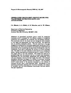
Figure 1: Layout of different configurations of loop elements FSS and its equivalent circuit. (a) Square loop. (b) Double square loop. (c) Gridded square loop.
(a)
(b)
(c)
(d)
Figure 2: (a) Equivalent RL circuit for real pole synthesis; (b) equivalent series RLC circuit; (c) equivalent parallel RLC circuit for complex pole pair synthesis, and (d) equivalent Π circuit.
PIERS Proceedings, Guangzhou, China, August 25–28, 2014
2396
In this paper, we present the analysis and equivalent circuit modeling of three different configurations of loop elements based FSS, with resonant unit cells. The elements studied are 1) Square loop [2–4], 2) Double square loop [2, 5] and 3) Gridded square loop [2, 5], which are shown in Figure 1 along with equivalent circuits traditionally used to model them. For modeling purpose, vector fitting (VF) technique [6] is used for determination of poles and residues from simulated S-parameters obtained from full wave simulation tool CST Microwave Studio [7]. Then the SPICE-compatible equivalent circuit model [8] of frequency-domain responses approximated by rational functions are developed. The transmission and reflection properties are evaluated through a simple and accurate circuit approach. The developed models are within 1% of average deviation against reference data. 2. EQUIVALENT CIRCUIT MODELING BY VECTOR FITTING
VF method is a general fitting methodology which gives unconditional stability by forcing real terms of poles to become negative and is represented by the rational function approximation [6] as shown in Equation (1). N X cn + d + sh (1) f (s) = s − an n=1
w = 4.5 mm, g = 0.9 mm, d = 2.25 mm and L = 9 mm
(a)
(b)
w1 = 2.5 mm, g1= 0.25 mm, w2 = 5 mm, g 2 = 0.5 mm, d = 1.5 mm and L = 9 mm
(c)
(d)
w 1= 2.5 mm, g 1= 0.25 mm, w2 = 6.5 mm, g 2 = 0.25 mm, d = 1 mm and L = 9 mm
(e)
(f)
Figure 3: Plane-wave reflection response for different configurations of loop elements in FSS. (a) Square Loop — normal incidence. (b) Square Loop — oblique incidence. (c) Double Square Loop — normal incidence. (d) Double Square Loop — oblique incidence. (e) Gridded Square Loop — normal incidence. (f) Gridded Square Loop — oblique incidence.
Progress In Electromagnetics Research Symposium Proceedings, Guangzhou, China, Aug. 25–28, 2014 2397
The residues cn and poles an are either real quantities or come in complex conjugate pairs, while d and h are real. It gives the fractional terms that directly lead to fixed forms of R, L and C. In this section, circuit representations for complex pairs obtained from VF and synthesis approach are presented briefly for the generation of SPICE [8] compatible equivalent circuits enabling both time and frequency analyses of square loop, double square loop from three-dimensional models. The detailed synthesis of a complex pole pair by means of RLC elements with only one controlled source, allowing rational approximation of impedances or admittances to be implemented in a circuit simulator along with the equations can be obtained from [8]. The following synthesis approach has been used in this work to achieve the SPICE-compatible equivalent circuits of loop elements based FSS microstructure: Step 1) S-parameter extraction by means of simulation of FSS microstructure in CST Microwave Studio; Step 2) ABCD parameters evaluation; Step 3) Building of the equivalent circuit as shown in Figure 2(d); Step 4) Residues and poles extraction of admittances Y¯A , Y¯B and Y¯ ; Step 5) SPICE-compatible equivalent circuit synthesis [8]. The VF technique has been adopted to extract poles and residues of admittances Y¯A , Y¯B and ¯ Y , which have been synthesized in the equivalent circuit, as shown in Figures 2(a)–2(c), of FSS
(a)
(b)
(c)
(d)
(e)
(f)
Figure 4: Comparison of VF based equivalent circuit model against CST and traditional circuit model for different configurations of loop elements based FSS (Substrate: εr = 4.4, tan δ = 0.025 and h = 1 mm).
2398
PIERS Proceedings, Guangzhou, China, August 25–28, 2014
microstructure and simulated in a ADS SPICE [9] environment enabling both time and frequency analyses. 3. PARAMETRIC STUDY AND MODEL VALIDATION
This section is dedicated to the validation of the presented equivalent circuit models for three different configurations of loop elements in FSS. Firstly, different configurations of loop elements based FSS structures are studied and investigated on single-substrate for different physical parameters using CST Microwave Studio [10]. The effects of oblique incidence and TE/TM polarization are also studied. All the FSS designs are simulated on FR4 substrate with permittivity εr = 4.4, loss tangent tan δ = 0.025 and substrate thickness h = 1 mm. For the sake of brevity, few results are shown here. Figure 3 shows the reflection characteristics at normal incidence for different loop sizes and the effect of oblique incidence and TE/TM polarization on its magnitude of square loop, double square loop and gridded square loop respectively. It has been observed in all the three configurations of FSS that by increasing loop size there is shift in resonance towards lower frequency and by increasing substrate thickness, there is shift in resonance towards lower frequency. Figure 4 shows the compared results of magnitude and phase of reflection and transmission characteristics at normal incidence obtained from the developed circuit model using VF tool, circuit model available from literature and CST simulations for square loop, double square loop and gridded square loop respectively. The reflection and transmission coefficients of square loop have been fitted by using 10 poles (two real poles and four complex pairs); double square loop and gridded square loop using 12 poles (two real poles and five complex pairs) respectively [6]. The extracted pole pairs obtained using fitting procedure can be synthesized in ADS SPICE generator using repeated equivalent circuit units shown in Figure 2. The results of the developed equivalent circuit model showed good agreement, up to the propagation of high-order Floquet modes. Thus proposed synthesis allows a satisfactory approximation of all the considered FSS being the percentage errors on magnitude and phase of the order of 1%. While the equivalent circuits available in literature have the percentage errors on magnitude and phase of the order of 1.5%. All the equivalent circuits are designed and simulated using ADS SPICE generator. In future work, this approach will be extended to multilayer substrates. 4. CONCLUSIONS
The present work reports development of vector-fitting based equivalent circuit model of three different configurations of loop elements based FSS, with resonant unit cells. The elements studied are — 1) Square loop, 2) Double square loop and 3) Gridded square loop. The simulations are performed with CST Microwave Studio on single-substrate for different physical parameters, oblique incidence and effect of TE/TM polarization. The VF tool is employed to extract equivalent circuits from S-parameters of FSS microstructure to use in circuit simulators to avoid time consuming 3D simulations. Then ADS SPICE generator is used for verifying circuit models developed using simulated results. All the models are within 1% of average deviation against reference data. ACKNOWLEDGMENT
This research work has been supported by Shenzhen Key Laboratory of Meta-RF Fabrication and Packaging (No. CXB201109210102A), Guangdong Natural Science Funds for Distinguished Young Scholar (No. S20120011253) and the introduction of innovative R&D team program of Guangdong Province (No. 2011D024). REFERENCES
1. Costa, F., A. Monorchio, and G. Manara, “Efficient analysis of frequency-selective surfaces by a simple equivalent-circuit model,” IEEE Antennas and Propagation Magazine, Vol. 54, No. 4, 35–48, 2012. 2. Munk, B. A., Frequency-selective Surfaces: Theory and Design, Wiley, New York, 2000. 3. Chung, Y.-C., K.-W. Lee, I.-P. Hong, M.-G. Lee, H.-J. Chun, and J.-G. Yook, “Simple prediction of FSS radome transmission characteristics using an FSS equivalent circuit model,” IEICE Electronics Express, Vol. 8, No. 2, 89–95, 2011. 4. Lee, C. K. and R. J. Langley, “Equivalent-circuit models for frequency-selective surfaces at oblique angle of incidence,” IEE Proc., Vol. 132, No. 6, 395–399, 1985.
Progress In Electromagnetics Research Symposium Proceedings, Guangzhou, China, Aug. 25–28, 2014 2399
5. Singh, D., A. Kumar, S. Meena, and V. Aggarwal, “Analysis of frequency selective surfaces for radar absorbing materials,” Progress In Electromagnetics Research B, Vol. 38, 297–314, 2012. 6. Gustavsen, B. and A. Semlyen, “Rational approximation of frequency domain responses by vector fitting,” IEEE Trans. Power Delivery, Vol. 14, 1052–1061, 1999. 7. CST Studio Suite, CST GmbH — Computer Simulation Technology, 2011, www.cst.com. 8. Antonini, G., “SPICE equivalent circuits of frequency-domain responses,” IEEE Trans. on Electromagnetic Compatibility, Vol. 45, 502–512, 2003. 9. Agilent Advanced Design System, 2011. 10. Majumdar, P., Z. Zhao, and R. Liu, “Parametric analysis of different configurations of loop elements in frequency-selective surfaces,” Advance in Electronic and Electric Engineering, Vol. 4, No. 2, 161–168, 2014.