a local approach to solve errors directly at the UMTS link layer while keeping a .... FEC is to reduce the residual packet loss probability at the link layer, thereby ...
Error Control Techniques for Efficient Multicast Streaming in UMTS Networks: Proposals and Performance Evaluation Michele ROSSI Department of Engineering, University of Ferrara Saragat 1, ZIP 44100, Ferrara, Italy and Frank H. P. FITZEK Aalborg University, Head of Future Visions Niels Jernes Vej 12, ZIP 9220, Aalborg, Denmark and Michele ZORZI Department of Information Engineering, University of Padova via Gradenigo 6/B, ZIP 35131, Padova, Italy
Abstract— In this paper we introduce techniques for efficient multicast video streaming in UMTS networks where a video content has to be conveyed to multiple users in the same cell. Efficient multicast data delivery in UMTS is still an open issue. In particular, suitable solutions have to be found to cope with wireless channel errors, while maintaining both an acceptable channel utilization and a controlled delivery delay over the wireless link between the serving base station and the mobile terminals. Here, we first highlight that standard solutions such as unequal error protection (UEP) of the video flow are ineffective in the UMTS systems due to its inherent large feedback delay at the link layer (Radio Link Control, RLC). Subsequently, we propose a local approach to solve errors directly at the UMTS link layer while keeping a reasonably high channel efficiency and saving, as much as possible, system resources. The solution that we propose in this paper is based on the usage of the common channel to serve all the interested users in a cell. In this way, we can save resources with respect to the case where multiple dedicated channels are allocated for every user. In addition to that, we present a hybrid ARQ (HARQ) proactive protocol that, at the cost of some redundancy (added to the link layer flow), is able to consistently improve the channel efficiency with respect to the plain ARQ case, by therefore making the use of a single common channel for multicast data delivery feasible. In the last part of the paper we give some hints for future research, by envisioning the usage of the aforementioned error control protocols with suitably encoded video streams.
Index Terms – UMTS, Multicast Streaming, Error Control, FEC, Hybrid ARQ, Common Channel, Dedicated Channel, Video Quality, PSNR. I. I NTRODUCTION UMTS networks [1] are currently becoming a reality in some parts of Europe, while in other parts they will be deployed within the next few years. After the high investment costs of hundreds of billion of Euro spent in Europe for the This work has been partially supported by ERICSSON research and the European Commission under the Contract IST-2002-2.3.1.4507134 (Ambient Networks). The views and conclusions contained herein are those of the authors and should not be interpreted as necessarily representing the Ambient Networks Project.
license band to support 3rd generation technology, further costs, which may likely be of the same amount, will come up for the installation of this technology. As a consequence to that, network providers are now interested in a fast return of investments. However, to convince customers to join UMTS technologies, network providers need to enable new services such as mixed audio/video multimedia flows that, in contrast to voice services, are characterized by higher bandwidth requirements which can be substantially higher than the ones required by a single voice service. The dilemma for the network provider can therefore be described as follows: on the one hand new services are needed, in fact, speech and data services are already provided in a cost efficient manner within GSM/GPRS networks and will not therefore motivate customers to join the UMTS technology. On the other hand, video services, that have the potential of motivating new users to join the UMTS technology, can not be billed with the same Cent per bit ratio as voice calls, because no customer could then afford such services. Of course, one may think of decreasing the video quality such that to lower the bandwidth required to transmit video contents, but this may not satisfy the customers’ requirements. In this scenario, it is therefore pivotal to design algorithms which enable the transmission of bandwidth demanding services to the users in an efficient manner from both user and operator perspectives, so that their price can still be competitive with already existing services. The solution presented in this paper advocates the usage of multicast capability to make video transmissions interesting for the customer improving the Cent per bit ratio while maintaining a high video quality. This approach is only valid in the case where multiple customers per cell are interested in the same content. Multicast can be applied in two different ways to the UMTS network: the content is conveyed to the wireless end system using either the Dedicated (DCH) or the Common CHannel (CCH) of UMTS [1]. The advantage of the dedicated channel (DCH) is that a separate channel is maintained for each wireless terminal and that fast power and
error control can be implemented independently for every user. Within the second approach (CCH), multiple wireless terminals can be subscribed to the common channel. Here, no fast power control is performed and the error control has to be realized differently, i.e., retransmissions are needed if at least one among the served users does not correctly receive any portion of the transmitted data. This fact, as will be shown in the sequel, in certain cases considerably affects the common channel transmission efficiency. Moreover, the advantage of using a common channel is due to the fact that that the transmission of the flow requires less bandwidth in contrast to the exploitation of multiple channels, where a copy of the same content is, in fact, replicated and transmitted in parallel to the different users. The aim of the paper is first to clearly state the problem of multicast streaming delivery in a UMTS network, with particular emphasis to its efficient delivery over the wireless channel. Note that, methods to apply multicast in the UMTS backbone are out of the scope of this paper. Afterwards, we propose an effective solution to achieve error control while keeping the channel efficiency at a high value. An example shall explain our approach. In the case where only one customer is interested in a specific content, we use a dedicated channel. However, as multiple customers are interested in such a content we have two possibilities to convey this flow, i.e., exploiting multiple dedicated channels (DCHs) or rather using a single common channel (CCH). It is generally accepted that wireless links are highly error-prone, and that therefore error control is a very important key feature for the transmission over them. In particular, while for each dedicated channel the error control scheme can be initialized and specifically tailored to the characteristics of the link, the error control over the common channel has (in general) to be realized satisfying the wireless terminal with the worst link. As an example, think of a simple ARQ strategy such as Send and Wait: each time that only one wireless terminal out of the multicast group asks for a retransmission, the filling procedure of the play-out buffer is stalled for all remaining users. Moreover, in case where only a limited number of retransmissions per packet are allowed, the performance at the application layer may suffer. Of course, the performance degradation in this case strongly depends on the considered video encoder as well as its chosen parameters. It is therefore understandable that, in general, plain ARQ strategies are not the most suitable to be used when CCH transmissions are at play. As said above, this is mainly motivated by the fact that, besides reliability, video streaming applications also have strict delay and throughput requirements that could make classical ARQ approaches ineffective. Error control algorithms can be classified into FEC, ARQ and hybrid ARQ (HARQ) techniques. Forward Error Correction (FEC) is based on the transmission of redundant information through error correction codes. In ARQ a feedback link is used to request retransmission of erroneous packets. Hybrid ARQ schemes combine the advantages offered by FEC and ARQ. The efficient data delivery to a group of multicast receiver through HARQ has been studied for the first time in [2]. A further contribution in this sense can be found in [3]. In both these papers, the authors analytically derive relationships between channel efficiency (expressed as average number of
transmission per correctly delivered multicast packet) and the multicast group size, by considering both independent and correlated packet losses. In particular, in [3] two key problems are addressed: the efficiency of hybrid ARQ protocols and the comparison between integrated and layered FEC. In layered FEC the packet coding operates independently beneath ARQ (or Reliable Multicast, RM) layer. In this case, the role of FEC is to reduce the residual packet loss probability at the link layer, thereby decreasing the number of retransmissions and, as a consequence, the network bandwidth requirements. In the integrated model, FEC and ARQ are integrated into the same layer and the FEC module operates as follows: for a given set of data packets it computes and holds a set of parity packets. Then, once the sender has received all the retransmission requests across the feedback channel, it transmits the minimum number of parity packets needed to recover all the losses in the original data set. Integrated FEC gives better performance than layered FEC [3]. Another interesting framework for reliable and efficient multicast delivery can be found in [4]. In this thesis, a large quantity of material on the topic can be found and, among other issues, the author presents some techniques to estimate the number of multicast receivers based on the number of NACKs received at the sender side. [6][7] and [8] are three further papers where the authors focus on the design of reliable multicast protocols using HARQ. The obtained results show that pro-actively sending a (usually small) number of redundancy packets along with the original data can improve efficiency and could reduce feedback. In these contributions the NACK implosion problem is also analyzed and it is proven that pro-actively sending a given amount of redundancy packets along with the original data highly reduces the number of retransmission requests from the receivers, thereby enabling the multicast group to grow up to thousands of users. In all the aforementioned work, the authors consider a packet-based Reed Solomon Encoder (RSE) as the one presented in [9][10], where a software implementation of this encoder can also be found. In particular, in [9][10] it is shown that software implementations of RSE decoder/encoder are feasible in the sense that, even if run over very slow processors, they lead to very short (tolerable) encoding and decoding delays. This is very important as it enables the use of such a packet-based coding scheme directly at the Reliable Multicast (RM) level. For instance, referring to our UMTS scenario and considering to have a highly reliable fixed network, the problem is the multicast delivery from the Node B [1] to the mobile systems linked with it and subscribed to the multicast group. Hence, it could be very interesting to apply such a RSE approach directly at the link layer (RLC), taking link layer packets (PDUs) as the packet units to be used for coding. In this case, most of the work in previously presented papers still applies. In addition to the RSE encoder presented in [9][10], one could think of using Tornado codes [11]. This latter approach is conceptually similar to the one represented by RSE coding schemes but encoding and decoding algorithms are much faster. In [12] and [13], the authors present the RDMP protocol. In RDMP packet based FEC is combined with ARQ to transmit multicast messages over the single common forward channel. In addition to that, the feedback channel is shared
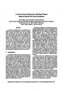
among users. To limit the ACK collision problem the authors rely on the intelligent use of FEC together with a back-off algorithm to decide when ACKs have actually to be sent by the users. These strategies are intended to reduce the NACK collision probability over the feedback channel. As a further contribution to the transmission of multicast data over wireless channels, we report here the Pragmatic General Multicast (PGM) protocol [14], which has been recently proposed and now it is an Internet Engineering Task Force (IETF) experimental Request For Comment (RFC). PGM exploits packet-based coding NACK suppression and NACK elimination to provide reliable data delivery while achieving a high channel efficiency over asymmetric networks. Most of these contributions refer to the case of multicast transmission over wire-line networks, but we stress that similar approaches can be extended to the wireless case as well. This, in fact, is the main purpose of this paper where we show that, if opportunely tuned, these approaches are beneficial also over UMTS wireless links. In the present paper we go further with respect to previous research by proposing algorithms specifically tailored for the UMTS cellular network scenario. In particular, we use the incremental redundancy concept to provide retransmissions and we characterize the proposed schemes considering both delay and channel efficiency. Furthermore, for what concerns delay performance, we consider full delay statistics instead of mean values. Moreover, since the main scope of our ongoing research is to design algorithms for real environments, we highlight the behavior of the proposed schemes over correlated channels. To this end, we characterize the link layer error process for each multicast user by means of a two-state Markov chain. The paper is organized as follows: In section II we first present a brief overview of the possible ways of delivering a multicast flow in a UMTS network. Then, we present and motivate the best suitable way of conveying the multicast flow in terms of logical channels to be allocated. In section III, we present the system model and the basic way in which error control can be achieved (plain ARQ). In section IV we briefly introduce packet-based error correcting codes by explaining their benefits and the involved trade-offs. These codes are used at the link layer level in addition to plain ARQ techniques in order to improve performance. Hybrid ARQ algorithms are then proposed and detailed in section V. In section VI we evaluate their performance both in terms of channel efficiency and delay by considering independent packet errors. In section VI-B we investigate the effect of the error burstiness, whereas in section VI-C we consider a further interleaving technique on the forward packet flow in order to improve the robustness against error bursts. In section VII we report some conclusions and finally, in section VIII, we discuss possible directions for further research. II. T HE UMTS N ETWORK A RCHITECTURE In Figure 1 we report the involved entities for video streaming in the UMTS networks and the related protocol stacks. Here we refer to the specific case where streaming data arrives from an Internet server to the UMTS mobile terminals in a timely manner. The physical placement of the server, within the IMS (IP Multimedia Subsystem) or the Internet, is out of the scope of this paper. It is important
to observe that the IP level is not available on all entities along the path. In particular, only the User Equipment (UE), the SGSN/GGSN (Serving/Gateway GPRS Support Mode) and the Internet server are equipped with an IP layer. For this reason, they are the only terminals which are able to manage video frames and to eventually take advantage from channel adaptive video coding techniques [17][18][19] (where Unequal Error Protection (UEP) is usually employed to improve the video flow robustness against packet losses). In these algorithms, the channel quality is monitored by means of feedback information and, based on it, an estimate of the video quality perceived at the end user is exploited to trigger both the frame compression process and the amount of redundancy added to each video frame. The effectiveness of this approach depends on the time it takes for the feedback to reach the sending entity. If this time is too long with respect to the stationarity period characterizing the underlying error process, an inertial effect will arise in the error control actions. In such cases, the feedback information is ineffective, since the forward flow adapts too slowly to the underlying error sequence and the user quality could therefore be worse than without using adaptation at all. Here, we stress the fact that this last case is the one envisioned in a UMTS network, where End-to-End delays can be up to 0.5 seconds. Hence, standard solutions based on End-to-End video frames adaptation seem not to be the correct way to improve the video quality is such networks. On the other hand, noting that the main cause of errors is due to the wireless link, one could think to implement some kind of error control mechanism restricted to the Radio Access Network (RAN). In this way, the round trip delay is strongly reduced1 . However, the drawback of this solution is that is not possible to operate directly on the video flow, because the UE is the only terminal in the RAN that has access to the IP flow. For this reason, we advocate to perform error control at the Radio Link Control layer (RLC) that is present in both the UE and SRNC (Serving Radio Network Controller). As observed above, we can not operate directly on the video frame flow, but on the other hand we have RLC native feedback information that can be used to drive channel adaptive algorithms. Moreover, in our solution we think to jointly utilize, at the RLC layer, retransmissions and packetbased encoding techniques in order to enhance the channel efficiency while using a single CCH channel to serve all users. The model for the ARQ transmission/retransmission process is presented in the next section, whereas in Section IV we briefly introduce the packet-based FEC technique that will be incorporated in our hybrid ARQ schemes. The hybrid ARQ algorithms will be presented in detail in Section V. III. M ODEL FOR ARQ E RROR C ONTROL P ROCESS We consider an Internet server sending a single video stream to a multicast group located in the UMTS network. Moreover, we consider a single UMTS cell and that a given number of users Nu within the cell is interested in the reception of the flow. We refer as N to the set of multicast user in the cell, where the number of users in N is referred to as Nu = |N |. Without loosing in generality, we consider that only one multicast group exists in the cell and we 1 Up to 220 ms at the RLC layer, its actual value depends on the interleaving depth set at the underlying physical layer.
Video/RTP/UDP
Application
encoded data
Application
TCP/UDP
TCP/UDP IP
IP
received data
source data
reconstructed data
IP
PDCP PDCP
RLC PHY
wireless channel
MAC
PHY PHY Uu UE
GTP−U
GTP−U
MAC−d
RLC
UDP
FP
FP
FP
FP
FP
AAL2
AAL2
AAL2
AAL2
AAL2
ATM
ATM
ATM
ATM
ATM
Iub
Node B
DRNC
Iur
SRNC
Decoder
Encoder AAL2 Iu
ATM
SGSN/GGSN
Server
K UMTS RAN
Core Network
K
Internet
N
Fig. 1.
Entities and Protocol Stack within the UMTS network.
investigate how bandwidth requirements and residual error rates at the application level are related to Nu and to the error processes characterizing the link layer at each user. In our model, the time axis at the RLC layer is slotted, where the slot time corresponds to the single link layer packet (PDU) transmission duration. Moreover, we consider a Discrete Time two-state Markov Channel (DTMC) to describe the PDU error process affecting each user in N . In more detail, the channel is characterized by two states, a “good state” (state 0), where PDUs are transmitted correctly and a “bad state” (state 1), where PDUs are corrupted with probability one. This simple model evolves slot by slot according to its transition probabilities; we refer to as pij (u), i, j ∈ {0, 1} to the probability that the channel of user u transits in state j in the next slot given that, in the current one it is in state i. We refer as P(u) to the channel transition probability matrix relative to user u. The plain2 RLC transmission/retransmission process is modeled as follows:
>=K
Fig. 2. Packet-based encoding/decoding process. The original K PDUs can be reconstructed if a number of PDUs equal to or greater than K is correctly received out of the N sent PDUs (FEC block).
•
•
queue and to re-send it when the relative NACK arrives3 . If a packet is correctly delivered4 in a given slot, say slot i, then a new link layer packet is taken from the link layer queue and is scheduled to be transmitted m slots apart, i.e., in slot i + m. We consider a Heavy Traffic assumption, i.e., a new packet to be sent is always present into the link layer queue. Note that this assumption is a good approximation of the incoming flow at the RLC layer when video/audio streaming is considered.
It is important to note that this model, despite of the numerous simplifications with respect to the real RLC level [20] leads to an upper bound for what concerns the forward link channel utilization because link layer PDUs are always retransmitted with the lowest latency (exactly after one round trip time from their previous transmission). Note also that multiple copies of the same PDU are never transmitted during a single round trip time (m slots). In real UMTS RLC implementations, depending on the specific RLC timer profile, situations where the same PDU is transmitted more than once in a round trip time might occur. Note that these configurations are sometimes forced to achieve short RLC SDU delivery delays at the cost of the forward channel throughput. In these particular cases the presented model is not a lower bound for the delay but it still be an upper bound for what concerns the throughput performance. Furthermore, in the scheme presented above one ACK is received for each PDU, i.e., we have one ACK for every slot in which a transmission occurs. This assumption is not always true in real systems, where ACK messages of different PDUs are often grouped into single messages called status reports [20]. However, the main aim of our work is on the characterization of delay and efficiency for what concerns the forward data flow, i.e., the one flowing from the SRNC to the UE.
At the sender side, higher level packets (Service Data Units, SDUs) are segmented into smaller packets, called PDUs. These packets are processed adding a header and a CRC (Cyclic Redundancy Check) field. These fields are needed, at the receiver, to check for the correctness of each packet (CRC) and to perform the reassembly of link layer PDUs. At the receiver side, every PDU is checked using its CRC field and, based on the outcomes of this operation, a retransmission for that packet is possibly required. This retransmission is achieved by sending over the reverse link a negative acknowledgment (NACK) message. At the receiver side, link layer PDUs are used to reconstruct higher layer SDUs. SDUs can be passed to higher levels using either in-order or out-of-order delivery [20]. The link layer experiences a round trip time that, for simplicity, is considered to be an integer number of channel slots, m, i.e., a integer number of PDU (packet) transmission times. A given PDU is considered to be in error in a given slot if at least one multicast user does not correctly receive it. If a given packet is transmitted erroneously in a given slot, say slot i, then it must be retransmitted m slots apart, i.e., in slot i + m. This operation is equivalent to inserting that packet into the link layer retransmission
IV. PACKET- BASED FEC T ECHNIQUES Forward Error Correction (FEC) techniques involve the transmission of original packets along with additional redundant data which are used to reconstruct the original data is some of it is lost. One possible family of codes for packetbased encoding is the Reed-Solomon one [2]. These are blockbased error correcting codes with a wide range of applications
2 This is the simplest ARQ mechanism, further extensions taking into account packet-based coding techniques will be presented in Section V.
3 Without loss in generality NACK and ACK messages are considered to be error free. 4 All users have correctly received the packet.
•
•
•
•
•
•
in digital communications and storage. The Reed-Solomon encoder takes a block of digital data and adds redundant bits, while on the receiving side the decoder processes each block and attempts to correct errors and recover the original data. The number and type of errors that can be corrected depends on the characteristics of the code. In more detail, Reed Solomon codes are a subset of BCH codes and are linear block codes. A Reed-Solomon code is specified as RS(k, n). This means that the encoder takes k data symbols of s bits each and adds parity symbols to make an n symbol codeword. There are n − k parity symbols of s bits each (where s is the size of each symbol). The correcting capability of an RS code depends on n − k. A RS decoder can correct up to and including t symbols that contain errors in a codeword, where t = b(n − k)/2c. However, the decoder can correct more than t symbols if it knows where the errors are. These known error locations are called erasures. The key idea behind erasures is that K blocks (packets) of source data are encoded at the sender to produce N blocks of encoded data, in such a way that any subset of K encoded blocks suffices to reconstruct the source data. Such a code is called a (K, N ) erasure code (RSE code) and allows the receiver to recover from up to N − K losses in a group of N encoded blocks (packets) [2][3]. In each packet a Cyclic Redundancy Check (CRC) field must be present to detect errors (erasures). Note that this feature comes for free at the UMTS RLC layer. In Figure 2, we report a graphical representation of the encoding/decoding process. Assume to have K source information packets, {d1 , d2 , . . . , dK } each of which is P bits long. The RSE encoder takes these K packets and produces N − K parity packets {p1 , p2 , . . . , pN −K }. Then the original K data packets plus the N − K parity packets are sent along over the channel. Each FEC block of N packets is commonly referred to as transmission group (TG) [2]. At the receiver side it is sufficient that K of these N packets are received correctly in any order to reconstruct the original K packets (see Figure 2). Most RSE implementations send the first K original data as the first K packets to simplify decoding (systematic code). In this way, if all the K data packets are correctly received, no decoding at all is required at the receiver. If due to channel error, at the receiver side l ≤ min(K, N − K) < N − K packets have to be reconstructed, the decoding overhead is proportional to l (see [10]). Especially in the cases of multicast transmission, there are additional benefits in using the parity packets for loss recovery instead of transmitting the lost packets: •
•
Improved transmission efficiency: A single parity packet can be used to repair the loss of any packet in the TG. This means that a single parity packet can repair the loss of different data packets at different receivers. This fact is extremely useful since different receivers are in general affected by independent error processes. Improved scalability in terms of group size: In ARQ schemes the sender needs to know the sequence number of each lost packet. Instead, using parity packets for loss repair, the sender needs to only know the maximum number of packets lost by any receiver but not their sequence number. So, the feedback is reduced from per-
Block Start
Encode H redundancy PDUs
Transmit a new TG (N PDUs)
YES
RX NACK for the TG
NO
RETX the TG
Fig. 3.
Sender protocol for the algorithm A1.
Block Start
Encode H redundancy PDUs
Transmit a new TG (N PDUs)
YES
RX NACK for the TG
NO
Encode R new redundancy PDUs for the TG
TX R redundancy PDUs
Fig. 4.
Sender protocol for algorithms A2 and A3.
packet feedback to per-TG feedback. In fact, depending on the number of lost packets, a given amount of new redundancy packets, obtained by the original K packets, can be transmitted over the channel (incremental redundancy) so that the original data is recovered if at least K packets are correctly received among all the received packets for the TG (N FEC block packets plus incremental redundancy packets). V. A LGORITHMS FOR M ULTICAST D ELIVERY In this section we propose three hybrid ARQ algorithms that can be used at the RLC level to improve both efficiency and delay performance with respect to the plain Selective Repeat ARQ scheme described in section III. The hybrid schemes are described in detail in the following: A1: The sender collects groups of K packets and then feeds them to the packet-based encoder by obtaining H redundancy PDUs so that a total number of N = K + H PDUs is available for each TG, as discussed in Section IV. The entire TG (N PDUs) is sent to all receivers over the CCH channel. Note that at the sender side some amount of redundancy (H PDUs) is proactively added to the forward multicast flow. As said above, this redundancy can be independently exploited by each multicast receiver to recover
the original K packets when the number of lost PDUs in a TG is less than or equal to H. When a multicast receiver is not able to correctly decode a TG it sends back to the transmitter a NACK message for that TG including the TG identifier. Finally, at the sender side, all NACKs for the same TG are collected and the entire TG is retransmitted if at least one multicast user required its retransmission, i.e., if the number of collected NACKs is greater than 0. A flow graph for this scheme is depicted in figure 3. As will be shown in the next, this solution gives good performance in terms of delay, but it is not very efficient in terms of throughput. At least one drawback is present in that scheme. In fact, a priori retransmitting all the PDUs in a TG may be not a good choice, because not all the receivers should need the retransmission of all the N PDUs and this may decrease the channel efficiency. A2: As in the previous scheme, at the sender side TGs of N PDUs each (K data packets plus H redundancy PDUs) are sent first. Then, each receiver checks for errors in each TG and replies accordingly. In more detail, if a receiver detects less than K correct PDUs for a TG it sends back to the sender a NACK including the TG identifier. The sender collects incoming NACKs and, if the number of collected NACKs for a given TG is larger than 0 the following procedure is executed: •
•
The K original PDUs included in the erroneously received TG are feed again to the packet-based encoder by obtaining a new redundancy packet, i.e., a redundancy packet for that TG that is however different from all redundancy packet previously transmitted. The new redundancy PDU (incremental redundancy) is sent over the CCH channel.
The flow graph for this scheme is plotted in figure 4. Referring to that figure we have that R = 1, i.e., the number of redundancy packets transmitted for each received NACK is always equal to one. In this scheme, each receiver collects all the received packets for a TG, i.e., the N PDUs sent in the first TG transmission plus the, say Rtot , redundancy PDUs sent in the following retransmissions (triggered by NACKs). The original K PDUs in a TG can be recovered if the number of correct PDUs, Nok , over the N + Rtot PDUs is greater than or equal to K. It is interesting to note that this scheme tries to maximize the channel efficiency. In fact, at each retransmission request the minimum amount of redundancy is retransmitted to all users (only one PDU). So, if at least one user needs more than one new PDU to obtain the K original data packets he will require a further retransmission. For this reason this scheme is also characterized by the longest delay for the correct delivery of a TG. A3: At the sender side TG of N PDUs (K data packets plus H redundancy PDUs) are sent first. Each receiver checks for errors in each TG and replies accordingly. In this scheme incremental redundancy is also used. To better explain as the algorithm works let us assume that, in addition to the N PDUs in the first transmission, R redundancy PDUs have already been sent over the channel for a given TG. In this case, each receiver checks for the number of correctly received PDUs (Nok ) among the N + R PDUs sent. Let us refer to a specific
user in N , say user i. If Nok (i) ≥ K the original K PDUs can be obtained and the TG is correctly received. Otherwise, if Nok (i) < K, the receiver sends back a NACK including the TG identifier and ri = K −Nok (i), i.e., the minimum number of new redundancy PDUs needed for the correct decoding of the K data PDUs. The sender collects incoming NACKs and computes Rmax = maxi∈N (ri ). Then, R = Rmax new redundancy PDUs are encoded for that TG and are transmitted over the common channel. This procedure is repeated until all users in N are able to correctly decode the K data PDUs, i.e., when Nok (i) ≥ K ∀i ∈ N . A flow graph for this scheme is reported in Figure 4, where the number of redundancy PDUs sent upon the reception of a NACK message is equal to Rmax , as specified above. This last scheme tries to achieve a trade-off between channel efficiency and delay. In fact, for each retransmission request, the minimum number (channel efficiency ↑) of PDUs needed to ensure that all multicast receiver will be able to recover the original K packets is sent (delay ↓). Note that Rmax new PDUs guarantee the successful decoding of a TG by all receivers only if no channel errors occur, or if channel errors are such that each receiver i is able to decode at least ri PDUs out of the Rmax transmitted. VI. R ESULTS In this section, the performance of the plain Selective Repeat ARQ (section III) is compared with the one provided by the three hybrid ARQ algorithms described above. This performance evaluation is carried out by considering three performance metrics: the first one consists of the common channel throughput, that may be defined as the number of data PDUs sent in a given time interval [0, t], Ndata (t), with respect to the total number Ntot (t) of PDUs transmitted. The average throughput can be obtained as throughput = limt→+∞ Ndata (t)/Ntot (t). This metric accounts for the channel resources consumed by redundancy and retransmissions. The remaining two metrics are relative to the delay needed to correctly receive a TG. Here, we define the RLC SDU delivery delay as the number of slots elapsed between the instant where the first PDU of a given RLC SDU is transmitted for the first time over the channel and the slot where all the multicast users in N correctly received the last PDU composing that SDU, i.e., all users in that “final” slot correctly received the entire SDU. Hence, the SDU delay computed in this way can be interpreted as a ”worst case“ SDU delay. We refer to the probability that a SDU is delivered in x ≥ 0 slots as Pd [x], whereas the complementary delivery delay distribution, i.e., the probability that a SDU is delivered in more than x slots is labeled as ccdf [x]. In the next sections, we report both the SDU mean delivery delay and its ccdf . Note that, in the video streaming case this metric (SDU delay) is directly related to the delay performance perceived at the UE IP level. In fact, the UDP protocol is typically used for streaming application. Hence, the delays experienced by higher layer IP packets in their transmission between the SRNC and the UE are entirely due to the RLC error control process and to all the additional delays involved in the physical layer processing5 . 5 In this paper we consider physical layer processing delays as constant and we include them in the link layer round trip time m.
400 350
0.1
300 0.01 250
ccdf[d]
mean SDU delivery time [ms]
1
ARQ A1, (K=15, N=19) A1, (K=19, N=26) 3/2 RTT+ 38 ln(Nu)
200
0.001
0.0001 150 ARQ, Nu=10 ARQ, Nu=100 A1, Nu=10 A1, Nu=100
1e-05
100 50
1e-06 1
10
100
1000
0
50
100
150
Nu
Fig. 5. Mean SDU transmission time as a function of the number of multicast users, Nu with ε = 0.1 and iid channel. Comparison between A1 scheme and selective repeat ARQ.
500
Mean SDU delivery delay [ms]
ccdf[d]
0.001 ARQ, IO ARQ, OOO A1, IO A1, OOO
0.0001 0
50
100
150
400
450
500
ARQ A1 A2 A3
450
0.01
350
Fig. 7. SDU complementary cumulative delivery delay statistics by varying Nu , ε = 0.1, iid channel, in-order delivery case. Comparison between A1 (K=15, N=19) scheme and selective repeat ARQ.
1
0.1
200 250 300 delay, d [ms]
400 350 300 250 200 150 100
200 250 300 delay, d [ms]
350
400
450
500
50 1
10
100
1000
Nu
Fig. 6. SDU complementary cumulative delivery delay statistics, Nu = 10, ε = 0.1, iid channel. Comparison between A1 (K=15, N=19) scheme and selective repeat ARQ.
Fig. 8. Mean SDU delivery delay time as a function of Nu , ε = 0.1, iid channel. K=15, N=19.
In the results discussed in the following sections we consider a link layer logical bit rate of 240 Kbps (spreading factor equal to 16) a RLC round trip time (RTT) of 80 ms (this is a lower bound for the RLC RTT in a UMTS network) and a link layer PDU length of 352 bits. With these values, we have about 56 PDUs in a link layer round trip time (m ≈ 56). Moreover, we consider a fixed SDU packet length of 500 bytes6 .
are characterized by an iid channel with the same PDU error probability ε = 0.1, i.e., εi = ε = 0.1, ∀i ∈ N . From this figure it is very interesting to observe that in the plain ARQ case, the behavior of the mean SDU transmission time is logarithmic in Nu . In other words, the SDU delivery delay tends to infinity as Nu increases. Also in the hybrid ARQ case the SDU delivery delay tends to infinity when Nu → ∞ but here the delay increases very slowly. This is a very important fact as it considerably improves the system scalability in terms of multicast group size. Moreover, we can note that a more powerful code is more insensitive to the multicast group size and it is able to keep the maximum SDU delay to a smaller value. In figure 6, we plot the ccdf by comparing the A1 scheme against plain ARQ. The multicast group size is Nu = 10. The labels IO and OOO are used to indicate the statistics regarding in-order and out-of-order delivery of RLC SDUs [20], respectively. The delay has been re-scaled in ms in order to allow for a better understanding of the quantities involved. Form this figure we can note that the SDU delivery delay is considerably reduced using hybrid ARQ. For example, for a delay d = 250 ms (in-order delivery case) plain ARQ
A. Performance over Independent Error Channels In this section, we consider that all multicast users are affected by independent (iid) PDU error processes and that the average PDU error probability for user i ∈ N is equal to ε i .7 As a first result, in figure 5, we report the mean SDU delivery delay, i.e., the mean time needed to correctly transmit a full SDU to all users in the multicast group as a function of the multicast group size, Nu , considering that all users 6 This is a typical value for the frame packet length in a video streaming flow [21]. 7 This can be achieved by setting p (i) = p (i) = ε , ∀i ∈ N . 11 01 i
0.9
1
0.8
0.9 0.8
Throughput
Throughput
0.7 0.6 0.5 0.4 ARQ 0.3 A1 A2 A3 0.2 1
ARQ, case I ARQ, case II A3, case I A3, case II
0.7 0.6 0.5 0.4 0.3
10
100
1000
Nu
Fig. 9. Throughput as a function of Nu , ε = 0.1, iid channel. K=15, N=19.
presents a probability of 0.3 (3 SDUs out of 10) that a SDU is transmitted in a time longer than d, whereas in the hybrid ARQ case the probability for the same event is of about 0.0001. Moreover, using the hybrid scheme, in-order and out-of-order delivery cases are almost equivalent, the only differences are for d up to 3RT T /2. So, the out-of-order delivery feature does not appear to give a significant gain when hybrid ARQ solutions are considered. The fact that in-order and in out-of-order cases are equal means that the delivery of a SDU in the in-order case for d ≥ 3RT T /2 does not depend on erroneous PDUs contained in previously transmitted SDUs. In other words, considering a tagged SDU and considering that the first PDU composing it is transmitted for the first time at time t1 = 0, the probability that a PDU transmitted before than the tagged SDU (time t2 < t1 ) is still erroneous at time t3 ≥ 3RT T /2 is negligible. This effect is due to the use of FEC. In figure 7 we observe that as the group size (Nu ) increases hybrid ARQ considerably limits the SDU delays. In particular, the SDU delivery statistics, after a certain point (in d ≈ 300 ms), starts decreasing very rapidly. On the contrary, the statistics regarding plain ARQ is just shifted to the right and without any shape change. This means that hybrid ARQ techniques are more robust with respect to an increasing number of multicast users in the system. The comparison between mean delivery delays between all schemes is plotted in figure 8. All hybrid schemes when Nu is small are characterized by a shorter delay with respect to plain ARQ. However, as Nu increases, scheme A2 quickly approaches ARQ performance. This is due to the fact that in A2 only one packet retransmission is allowed at a time. In this way channel resources are saved, but at the cost of a poor delay performance. On the other side, scheme A1 is the one characterized by the shortest delay. It is interesting to note that also scheme A3, where the minimum amount of redundancy is retransmitted so that all users can recover from errors, is able to keep the SDU delay to an acceptable value. Further, in figure 9 we report the channel efficiency as a function of Nu . As observed above, scheme A2 is the one characterized by the highest channel efficiency, whereas A1 is characterized by the worst one. All the hybrid algorithms outperform plain ARQ as Nu become larger than 3, i.e., when
0.2 0.0001
0.001
0.01
0.1
ε
Fig. 10. Robustness of hybrid ARQ schemes against a small number of users suffering from a bad channel condition. Nu = 100, A3 (K=15, N=19).
the multicast group is very small the overhead due to the proactively added redundancy in schemes A1, A2 and A3 (a priori data protection) is more channel consuming than performing retransmissions only (plain ARQ). However, it is important to note that hybrid ARQ schemes lead to a higher throughput as Nu increases beyond 3 and that for large Nu values they are still achieving a sufficiently high channel efficiency, whereas plain ARQ, in such a case, gives very poor throughput performance. Another interesting result is that performance of scheme A3 is very close to the upper bound (that, as observed above is given by scheme A2). Hence, this scheme may be a good candidate to be effectively used for multicast data delivery because it is characterized by a good channel efficiency and also its delay performance are not too worse with respect to scheme A1. Finally, in figure 10 we compare ARQ with scheme A3 considering Nu = 100 in the following two cases. Case I: all the 100 users are characterized by εi = ε, ∀i ∈ N , where ε is the PDU error probability reported in the abscissa of figure 10. Case II: 95 users are characterized by the error probability ε reported in the abscissa in figure 10, whereas the remaining 5 users are affected by a fixed error probability of 0.1. It is very interesting to note that the hybrid scheme in case II presents almost the same performance than in Case I. In other words, the hybrid ARQ is almost insensitive to a small number of users in a bad channel condition. On the contrary, simple ARQ performance is heavily degraded even when a small fraction of the users is affected by a bad channel state. This robustness is important to achieve a scheme that is effective against dynamic changes in the number of multicast user joining a group and to unpredictable changes in the users’ channel state. B. Effect of the Error Burstiness In this section we report some results on the effect of the channel burstiness on the hybrid ARQ performance. In particular, we refer to b(i) = 1/p10 (i) as the average burst length of user i ∈ N , where b(i) is the average number of subsequent slots (PDU transmissions) in which the channel of user i remains in the bad state. In figure 10 we plot the channel efficiency as a function of b, where we consider Nu = 10
0.75
simulation of the UMTS cellular system in order to assess the utility of having interleaving at the RLC level.
ARQ A1 A2 A3
0.7 0.65
C. Effectiveness of Interleaving on the RLC Packet Flow
Throughput
0.6 0.55
System Model
0.5 0.45 0.4 0.35 0.3 1
10 b
100
Fig. 11. Effect of the channel burstiness. ε = 0.1, Nu = 10, K=19, N=26.
multicast users all affected by the same burst length b(i) = b, ∀i ∈ N . We also consider that users have the same constant ε value of 0.1. The effect of the error burstiness must be surely taken into account since, depending on the cell load and on the distance between the Node B (base station) and the user, the CCH channel can be likely characterized by longer error burst than the dedicated one. Longer bursts are, in fact, likely measured near to cell borders, where the CCH downlink power should not suffices to counteract for path loss and user interference from the current and adjoining cells. In the dedicated channel case this phenomenon is less influent due to soft handover mechanisms. It is interesting to observe as the performance of hybrid ARQ schemes quickly degrades as b increases. Plain ARQ, instead, is more robust in this case. This results is quite obvious because when errors occur in burst, all the redundancy PDUs in a TG are likely lost as well as the first K data packets, i.e., in such cases, redundancy PDUs can not be used for recovery purpose. Among hybrid schemes, A1 is the worst one, A2 is the best, whereas A3 performs in the middle. Several solutions are possible to improve performance when channel errors occur in burst. First of all both K and N can be increased, by taking (for example) their ratio ρ = K/N = 1 − H/N constant. In this way it is more probable that the burst will affect only a fraction of the TG and that the remaining packets are sufficient (≥ K) to correctly decode it. However, this way of proceeding improves the performance at the cost of both a higher memory utilization at the packet-based decoder and at the expense of the delay performance (larger block sizes also implies a longer TG decoding time [10]). Another possible solution is to increase the PDU size by keeping constant K and N . The positive aspect of this solution is that the TG decoding speed increases [10], whereas the drawback is that the decoding process becomes more vulnerable to independent PDU errors. A further approach to improve robustness against error bursts is to perform interleaving over several TGs before actually send them over the channel. The drawbacks of this last method are the need for more memory and the presence of additional delays. In the next section, we present some preliminary results which have been obtained from accurate
In order to investigate the effectiveness of the interleaving approach introduced above, we developed an UMTS system simulator, where accurate channel traces can be achieved and used as the input for testing the proposed HARQ algorithms. We consider here a 3G cellular system, where W-CDMA is used as the radio interface. Moreover, as discussed above, we allocate Common CHannels (CCHs) for the local transmission (at every base station) of multicast data. Obviously, this choice is dictated by the need for an efficient utilization of the channel resources, as motivated above. In order to derive accurate channel traces for this system, a W-CDMA cellular system simulator has been developed. The reference scenario together with some details about the simulator are reported in the following. The service area is composed by Nc = 9 hexagonal cells, where a base station is placed at the center of each cell and a given number of users are mobile within the coverage area. Propagation phenomena are modeled through standard techniques, by considering log-normal slow fading, fast fading and path loss [23]. A simple power control algorithm has been implemented following the basic algorithm which can also be found in [16], i.e., the downlink transmitted power is dynamically varied by a constant multiplicative increase/decrease factor (∆ = 0.5 dB) to track a target SIR value (SIRth ). For what concerns channel coding and interleaving, we consider here a convolutional half rate Viterbi decoder operating over an interleaving interval T T I = 80 ms. A first set of users NDCH = 200 communicate through Dedicated CHannels (DCHs) whose bit rate is 30 Kbps (i.e., physical Spreading Factor of SFDCH = 128). These users are placed randomly at the beginning of the simulation and move following a pseudo-linear mobility model. The power control procedure is dynamically executed for each user as explained above. This first set of DCH users is regarded here as system interference since our main focus is on the common channel multicast transmission. A second set of users NCCH = 1000 receive the multicast flow through a Common downlink CHannel (CCH) whose bit-rate and spreading factor are Br = 120 Kbps and SFCCH = 16, respectively. These users can also be on the move, but their serving base stations remain unchanged. Let us better clarify this point. CCH users are randomly placed at the beginning of the simulation, shadowing and path loss are chosen according to the log-normal and the exponential model, respectively, and are kept constant for the whole simulation time. Subsequently, in order to emulate some degree of mobility, their Doppler frequency fd is selected, but without changing their spatial coordinates. In this way, we are able to control their fast fading as if they were on the move but without reflecting it into a change of their spatial positions. Therefore, it is possible to investigate multicast delivery algorithms (our main focus here) disregarding the multicast handover management that, by itself, constitutes a problem to be properly handled. The common channel power has been fixed to the constant value
N PDUs (data+redundancy)
1
I=B/N blocks
1 N+1
2 ...
H 3
K
... ...
N 2N
............ ...
...
(I−1)N+1 Fig. 12.
(I−1)N+K
IN
transmitted sequence
First RX Error Correction Probability
K
0.9
I=4
0.8 iid I=1
0.7 bursty
0.6 I=1, fd=40Hz I=4, fd=40Hz I=1, fd=2Hz I=4, fd=2Hz
0.5
0.4
Interleaving on the link layer TG flow (RLC PDUs).
0
0.1
Fig. 14. of H.
5
10 15 20 Redundancy H [nr. PDUs]
25
30
Link layer FEC error correction probability as a function
PDU error probability
0.01
0.001
0.0001
90% NO FEC 80% NO FEC 95%, H=20, K=100 80%, H=20, K=100 95%, H=10, K=50 80%, H=10, K=50
1e-05 1
10
100
Interleaving Buffer [Kbyte]
Fig. 13. Residual link layer PDU error rate: effectiveness of the interleaving approach on the link layer packet flow as a function of the interleaving buffer size (B).
PCCH = −5 dBW. Further details on the UMTS system simulator can be found in [23]. Interleaving Scheme As highlighted in previous research [3], packet-based FEC techniques are very effective to offer low residual PDU error rates to multiple users receiving the same data from a common transmission channel. However, the effectiveness of such techniques decreases as the link layer error burstiness increases. When error bursts are too long, the added redundancy is likely lost and it is useless in recovering from errors. In this case, the redundancy only wastes the available channel resources. To overcome this fact, we apply a matrix interleaving on the TG flow prior to its transmission over the channel. Let us refer to the interleaving buffer size (expressed here in number of RLC PDUs) at the RLC as B. Then, as reported in figure 12, PDUs are first disposed in a I × N matrix8 , where I = B/N is the interleaving depth. Thereafter, link layer PDUs are sent reading the matrix by columns, i.e., the transmitted sequence will be: {1, N + 1, 2N + 1, . . . , (I − 1)N + 1, 2, 2N + 2, (I − 1)N +2, . . . , N, 2N, . . . , IN }. Note that all PDUs belonging to the same block are transmitted over the channel spaced by 8 Matrix
indexes are expressed in units of PDUs.
I − 1 packets. As an example, in figure 13, the RLC packet residual error rate is reported for the 80-th and the 90-th percentile of the CCH users as a function of the interleaving buffer size. The graph has been obtained considering a first set of DCH users (NDCH = 200) that are on the move as explained above, while CCH (NCCH = 1000) users are static9 . It is worth noting that, if the interleaving buffer is large enough, the FEC can completely avoid losses in 80% (B = 10 Kbyte) and 90% (B ≈ 30 Kbyte) of the cases. Moreover, in order to gain some insights on how mobility (fd = 2 Hz) impact on the performance, in figure 14 we plot the FEC error correction probability by varying H, fd and I. The FEC error correction probability is defined here as the probability that the pro–actively added redundancy PDUs can successfully correct the errors occurring during the first transmission of a FEC block. In such a case we do not need further packets to be retransmitted. From figure 14 it is clear that the added redundancy is effective and that its convenience is higher over heavily correlated channels (fd = 2 Hz). VII. C ONCLUSIONS In this paper, we report some preliminary results and suggestions, which address the multicast data delivery problem in a UMTS system, where a multicast flow is transmitted over a common channel to different (multicast) users. Multicast user mobility is not considered, i.e., we do not address the problem of user handover between UMTS cells. Instead, both ARQ and packet-based FEC techniques are investigated considering both channel efficiency and delay performance. Three different Hybrid ARQ techniques (HARQ) are considered and compared against plain ARQ techniques. The following conclusions can be drawn: 1) Plain ARQ solutions do not suffice to obtain both good channel utilization and delivery delay performance as the number of multicast users increases. 2) Hybrid ARQ techniques are more robust against an increasing number of multicast users. They provide both 9 A Doppler frequency of f = 2 Hz has been considered in such d a case. Due to the low fd value, long RLC bursts are experienced by CCH users.
R EFERENCES 40
PSNR
35 30 25 IIIIIIIIIIII
20
IBBPBBSBBPBB
15 1e−09
1e−08
1e−07
1e−06
1e−05
bit error probability
Fig. 15.
Video quality versus bit error probability.
a high forward channel throughput and short delivery delays. However, packet-based FEC in order to be effective MUST be properly dimensioned, i.e., depending on the link layer error process observed at the receiver side. 3) For this reason the accurate characterization of such a link layer process is a pivotal point for the correct design of hybrid ARQ techniques. Finally, in section VI-C we investigated the effect of a further interleaving on the RLC PDU flow in order to increase the robustness of the HARQ approach against error bursts. In these settings, we prove that PDU level interleaving, if carefully configured, has the potential of substantially improving the performance. VIII. O UTLOOK In this paper we focused on the error-free transmission of the multicast content. However, as video codecs are able to deal with error prone payload, the used bandwidth may be further reduced by stopping the retransmission process in the case where a sufficient quality can be guaranteed at the mobile side (end user). In [22] we characterized the vulnerability, in terms of video PSNR, of H.26L video encoded bit streams in presence of bit errors. As an example taken from [22], in figure 15 we report the picture signal noise ratio (PSNR) as a function of the residual bit error probability at the application level. As highlighted in the figure, when the residual bit error probability (after physical and link layer operations) is below 10−6 , the video content can still be decoded with high quality (PSNR ≥ 35 dB). This fact can be used to disable retransmissions if the number of requesting mobiles is low (low number of returning NACKs). In addition, curves as the ones depicted in figure 15 may be used as utility functions in order to weight the perceived quality at the application layer as a function of the residual error rate after physical and link layer operations. These “utility curves” can therefore being used in order to design channel adaptive and users’ perceived QoS aware error control schemes, where retransmissions are provided based on the actual error rates at the application. In most cases, in fact, users can tolerate a small percentage of errors and still experiencing good video quality. This may be a feasible way of joining higher layers requirements with lower layer error control techniques and thereby trading-off reliability for channel efficiency.
[1] Web site: http://www.3gpp.org [2] C. Huitema, “The case for packet level FEC,” Proc. of IFIP 5th International Workshop on Protocols for High Speed Networks (PsHSN 1996), INRIA, Sophia Antipolis, FRANCE, Chapman & Hall. October 1996. [3] J. Nonnenmacher, E.W. Biersack, D. Towsley, “Parity-based loss recovery for reliable multicast transmission,” IEEE/ACM Transactions on Networking, vol. 6, no. 4, pp. 349–361. August 1998. [4] J. Nonnenmacher, “Reliable multicast transport to large groups,” Ph. D. Thesis. Ecole Polytechnique Federale de Lausanne. 1998. [5] A. J. McAuley, “Reliable broadband communications Using a Burst Erasure Correcting Code,” Proc. of ACM SIGCOMM 1990, pp. 287-306, Philadelphia, PA. September 1990. [6] D. Rubenstein, J. Kurose, D. Towsley, “Real-Time Reliable Multicast Using Proactive Forward Error Correction,” Proc. of IEEE NOSSDAV 1998, Cambridge, United Kingdom. July 1998. [7] D. Rubenstein, J. Kurose, D. Towsley, “Real-Time Reliable Multicast Using Proactive Forward Error Correction,” CMPSCI Tech. Report 98-19, University of Massachusetts at Amherst. March 1998. [8] R. Kumar, “Design and implementation of a Proactive RealTime Reliable Multicast Using Proactive Forward Error Correction (FEC),” Master Thesis, University of Massachusetts at Amherst. May 1998. [9] L. Rizzo, “On the feasibility of software FEC,” DEIT Technical Report LR-970131. Available as: http://www.iet.unipi.it/ luigi/softfec.ps [10] L. Rizzo, “Effective erasure codes for reliable computer communications protocols,” Computer Communication Review, April 1997. [11] J. W. Byers, M. Luby, M. Mitzenmacher, “Accessing multiple mirror sites in parallel: Using tornado codes to speed up downloads,” Proc. of IEEE INFOCOM 1999, pp. 275–283, New York, NY. March 1999. [12] L. Rizzo, L. Vicisano, “RMDP: an FEC-based Reliable Multicast protocol for Wireless environments,” ACM Mobile Computer and Communication Review, vol.2, no.2. April 1998. [13] L. Rizzo, L. Vicisano, “A Reliable Multicast data Distribution Protocol based on software FEC techniques (RMDP),” Proc. of the Fourth IEEE HPCS Workshop, Chalkidiki, Grece. June 1997. [14] J. Gemmel, T. Montgomery, T. Speakman, N. Bhaskar, J. Crowcroft, “The PGM Reliable Multicast Protocol,” IEEE Network, January/February 2003. [15] J. Laiho, A. Wacker, T. Novosad, “Radio Network Planning and Optimization for UMTS,” John Wiley & Sons, Ldt. October 2001. [16] H. Holma, A. Toskala, “WCDMA for UMTS: Radio Access for Third Generation Mobile Communications,” John Wiley & Sons, Ldt. 2000. [17] Bernd Girod, Jacob Chakareski, Mark Kalman, Yi J. Liang, Eric Setton, Rui Zhang, “Advances in Network-adaptive Video Streaming,” Wireless Communications and Mobile Computing, vol. 2, no. 6, pp. 549–552. September 2002. [18] U. Horn, K. Stuhlmuller, M. Link and B. Girod, “Robust Internet Video Transmission Based on Scalable Coding and Unequal Error Protection,” Image Communications, Special Issue on Real-time Video over the Internet, vol. 15, pp. 77–94. September 1999. [19] T. Stockhammer, H. Jenkac, C. Weiss, “Feedback and error protection strategies for wireless progressive video transmission,” IEEE Transactions on Circuits and Systems for Video Technology, vol. 12, no. 6, pp. 465–482. June 2002. [20] 3GPP TS 25.322, “Third Generation Partnership Project: Technical Specification Group Radio Acess Network; Radio Link Control (RLC) Specification (Release 5).” [21] Web site: http://www.acticom.info [22] F. H. P. Fitzek, P. Seeling, M. Reisslein, M. Rossi and M. Zorzi, “Investigation of the GoP Structure for H.26L Video Streams,” Technical Report: acticom–02–004, acticom – mobile networks. December 2002. [23] M. Zorzi, M. Rossi, and G. Mazzini, “Throughput and Energy Performance of TCP on a Wideband CDMA Air Interface, Wiley Wireless Commun. and Mobile Computing (WCMC), vol. 2, no. 1, pp. 71–84, February 2002.