Proc. of the 13th Int. Conference on Digital Audio Effects (DAFx-10), Graz, Austria , September 6-10, 2010
ESTIMATION AND MODELING OF PINNA-RELATED TRANSFER FUNCTIONS Michele Geronazzo,
Simone Spagnol,
Dept. of Information Engineering, Università di Padova Padova, Italy
[email protected]
Dept. of Information Engineering, Università di Padova Padova, Italy
[email protected]
Federico Avanzini, Dept. of Information Engineering, Università di Padova Padova, Italy
[email protected] ABSTRACT This paper considers the problem of modeling pinna-related transfer functions (PRTFs) for 3-D sound rendering. Following a structural modus operandi, we present an algorithm for the decomposition of PRTFs into ear resonances and frequency notches due to reflections over pinna cavities. Such an approach allows to control the evolution of each physical phenomenon separately through the design of two distinct filter blocks during PRTF synthesis. The resulting model is suitable for future integration into a structural head-related transfer function model, and for parametrization over anthropometrical measurements of a wide range of subjects. 1. INTRODUCTION The history of 3-D sound rendering dates back to Lord Rayleigh’s centenary Duplex Theory of Localization [1]. In this context, the well-known diffraction formula which approximates the behaviour of a sound wave produced by an infinite point source around the listener’s head provides a first crude sketch of what we today call a head-related transfer function (HRTF). On the other hand, most of the relevant issues in HRTF modeling have been faced in the last two decades only. HRTF-based spatial audio rendering can be achieved in multiple ways. Approximations based on low-order rational functions [2] and series expansions of HRTFs [3] were proposed, resulting in simple yet valuable tools for HRTF modeling. Nevertheless, significant computation is required from both techniques when real-time constraints are introduced, due to the complexity of filter coefficients and weights respectively. This is why structural modeling [4] seems nowadays to be an attractive alternative approach. Within this characterization, the contribution of the listener’s head, ears and torso to the HRTF are isolated in several subcomponents, each accounting for some well-defined physical phenomenon. Thanks to linearity of all these effects, they can be later combined meaningfully and realistically in an additive fashion to result in a global HRTF. Such a decomposition yields a model which is both economical and well-suited to real-time implementations. Our work focuses on the contribution of the pinna to the HRTF. Even though head motion cues are perceptually dominant, pinna
effects on incident sound waves still are of great importance in sound spatialization. Several experimental results have shown that while azimuth effects are dominated by diffraction around the listener’s head and may be reduced to simple and intuitive binaural quantities such as the Interaural Time Difference (ITD) and the Interaural Level Difference (ILD), elevation cues are basically monaural and strongly depend on the listener’s pinna shape, being the result of a combination of reflections and resonances in pinna cavities. Within this framework, it is crucial to find a suitable model for representing the pinna contribution to the HRTF, whose transfer function we will refer to as Pinna-Related Transfer Function (PRTF). Linking the model parameters to simple anthropometric measurements on the user’s pinnas represents the ultimate challenge in this direction. Once this model is available, cascading it to a simple Head-and-Torso (HAT) model [5] would yield a complete structural HRTF representation. This paper presents an iterative approach which aims at separating resonance effects from pinna reflections in experimentally measured PRTFs. Based on the estimated notches and resonances, a low-order filter pinna model suitable for anthropometric parametrization is proposed. 2. PRTF MODELING 2.1. Previous works According to Batteau’s theory [6], high-frequency components which arrive at the listener’s ear are typically reflected by the concha wall and rim, provided that their wavelength is small compared to the pinna dimensions. Due to interference between the direct wave and the reflected waves, sharp notches can be observed in the spectrum at high frequencies with a periodicity of 1/τi , where τi is the time delay of the i-th reflection. Such observation gave birth to a very simple multipath model of the pinna (see Figure 1), where the considered reflection paths are characterized by fixed reflection coefficients ρA and ρV , a fixed time delay τA and an elevation-dependent time delay τV . The fit with experimental data was found to be reasonably good; however, fixed reflection coefficients overestimate the effective number of notches in the spectrum.
DAFX-1
Proc. of the 13th Int. Conference on Digital Audio Effects (DAFx-10), Graz, Austria , September 6-10, 2010
Direct path
Concha reflection
ρA
τA
+
Rim reflection
ρV
τ v(δ)
Figure 1: Batteau’s multipath PRTF model.
A similar approach was adopted by Barreto et al., whose model [7] includes four parallel paths that represent the multiple bounces of the incoming sound wave on the geometrical structures of the pinna, each modeled by a time delay τi and a magnitude factor ρi explaining energy loss. Furthermore, since sound waves are also influenced by the effect of the pinna cavities acting as resonators, the reflection structure is cascaded to a low-order resonator block. The model parameters are fitted by decomposing each specific measured head-related impulse response (HRIR) into four scaled and delayed damped sinusoidal components using a procedure based on the second-order Steiglitz-McBride (STMCB) algorithm, and associating the delay and scaling factor of each component to the corresponding parameters of its associated path in the model. Multiple regression analysis was used in order to link the model parameters to eight measured anthropometric features [8]. Unfortunately, the considered measures are hard to obtain (a 3-D laser scanner is required); nevertheless, their work definitely emblematizes what this paper assumes the typical PRTF model to be, that is, a “resonance-plus-delay” structure. The approach taken by Raykar et al. for reflection modeling [9] is different and operates both in the time and frequency domains. Moved by the observation that raw pole-zero models merely approximate the HRTF spectrum envelope without bringing out the specific features one is looking for in the impulse response, the authors used robust digital signal processing techniques based on the residual of a linear prediction model for the HRIR to extract the frequencies of the spectral notches due to the pinna alone. Specifically, first the autocorrelation function of the HRIR’s windowed LP residual is computed; then, frequencies of the spectral notches are found as the local minima of the group-delay function of the windowed autocorrelation. The authors proved that the spectral notches estimated with this technique are related to the shape and anthropometry of the pinna: for each of the extracted notches the corresponding distance was plotted on the image of the pinna, and by varying elevation such mapping appeared consistent with reflections on the back of the concha and on the crus helias. Spectral peaks were extracted in parallel by means of a linear prediction analysis, yielding results which match quite well the pinna resonant modes reported by Shaw [10] (see Figure 2) and further justifying the “resonance-plus-delay” approach. Yet another relevant contribution on low-cost modeling of PRTFs was provided by Satarzadeh et al. [11]. Here PRTFs for elevations close to zero degrees are synthesized through a model composed of bandpass and comb filters, which respectively approximate resonances and notches. Two major resonances related to the concha
Figure 2: The six pinna modes identified by Shaw (Figure taken from [10]).
shape, specifically Shaw’s resonant modes 1 (quarter wavelength concha depth mode) and 4 (concha width mode), and one main reflection are considered. The two second-order bandpass filters
Hdepth +
Hcomb
Hwidth Figure 3: Satarzadeh’s PRTF model [11]. and the comb filter are interconnected as in Figure 3, the latter taking the form [1 + ρ exp(−sT )], where T is the time delay of the considered reflection estimated from the spacing of notches in the PRTF spectrum and ρ a frequency-dependent reflection coefficient which strongly attenuates low-frequency notches, coming over Batteau’s model aforementioned limitation. The model was proved to have sufficient adaptability to fit both PRTFs with rich and poor notch structures; furthermore, a cylindrical approximation to the concha was used with the purpose of directly parameterizing its coefficients. Specifically, depth and width of the cylinder uniquely define the depth resonance, while the width resonance is thought to be correlated to the time delay T depending on whether the concha or the rim is the significant reflector. Though the anthropometric significance of the two parameters is not robust, if the pinna has an approximately cylindrical shaped concha and a structure with a dominant reflection area (concha or rim), such an anthropometry-based filter provides a good fit to the experimental PRTF. 2.2. Our approach towards PRTF modeling Satarzadeh’s work has evidenced how a very simple model can incorporate the gross magnitude characteristics of the PRTF, by
DAFX-2
Proc. of the 13th Int. Conference on Digital Audio Effects (DAFx-10), Graz, Austria , September 6-10, 2010 straightforward parametrization on two physical measures. Unfortunately, besides considering solely the frontal direction of the sound wave, taking into account a single reflection seems to be a limiting factor: indeed, PRTFs with a poor notch structure do not exhibit a clear reflection in the impulse response. In addition, a cylinder is not an adequate physical model for the determination of the width mode of the pinna. Conversely, Raykar’s work features a very accurate procedure for determining spectral notches in PRTFs which provides interesting insight on the understanding of pinna reflections. Nevertheless, no actual PRTF model is defined. Taking these works and a “resonance-plus-delay” PRTF model as starting points, the first goal of this paper is to provide an algorithm for extracting from measured PRTFs an essential multi-notch filter suitable for anthropometric parametrization. Specifically, in Section 3 we describe an iterative procedure which aims at separating the reflective component of the PRTF spectrum from the resonant component. The results are discussed in Section 4 and, based upon this discussion, a structural pinna model is proposed.
BEGIN PRTF
Initialization ( 1) ( 1) Hres ,Hrefl
do ( i) H res
Nceps
Spectral envelope calculation, Cres
= (i) Eres H res /Cres Dmin Min. Extraction
3. PRTF ANALYSIS ALGORITHM
N=Nnch
For the purpose of analysis we consider measured HRIRs from the CIPIC database [12], a public domain database of high spatial resolution HRIR measurements at 1250 directions for 45 different subjects along with their anthropometry. Since sensitivity of PRTFs to azimuth is weak, we focus on HRIRs sampled on the median plane, with elevation varying from −45 to 90 degrees. Given that the magnitude response of the earless head with respect to a sound source in the median plane is essentially flat (it is ideally flat if the head is modeled as a rigid sphere), the only preprocessing step that is needed in order to obtain an estimate of the PRTF is to window the corresponding HRIR using a 1.0 ms Hann window. In this way, effects due to reflections caused by shoulders and torso are removed from the PRTF estimate. A similar preprocessing procedure was adopted by Raykar et al. [9] to estimate PRTFs from measured HRIRs. Figure 4 reports the complete flow chart of the analysis algorithm. The idea beyond it is to iteratively compensate the PRTF magnitude spectrum with an approximate multi-notch filter until no significant notches are left. Once convergence is reached (say (i) at iteration i), the PRTF spectrum Hres will contain the resonant (i) component, while the combination Href l of the multi-notch filters will provide the reflective component. The algorithm’s initial conditions heavily influence the final result; three parameters have to be chosen:
for j = 1: N fC Param. search D,fB
D ≥ D min ?
• ρ, the reduction factor for every notch filter bandwidth (its purpose will be discussed below). (1)
Before entering the core of the algorithm, let Hres match the (1) PRTF and set Href l to 1. These two frequency responses will be updated at each iteration, resulting in
(i) Hres
and
(i) Href l
at the begin-
(i)
ning of the i-th iteration. If Nnch is the number of “valid” notches algebraically identified at the end of it, the algorithm will terminate (i) (i) (i) at iteration i if Nnch = 0, while Hres and Href l will respectively contain the resonant and reflective components of the PRTF. As
DAFX-3
NO
YES
ρ
Notch filter construction (j) H nch
Multi-Notch filter assembly
• Nceps , the number of cepstral coefficients used for estimating the PRTF spectral envelope at each iteration; • Dmin , the minimum dB depth threshold for notches to be considered;
Nnch = Nnch - 1
H nch
H
(i) refl
(i) (i) update Hres ,Hrefl
until Nnch > 0 ( i) ( i) H res , H refl
END
Figure 4: Flow chart of the analysis algorithm.
Proc. of the 13th Int. Conference on Digital Audio Effects (DAFx-10), Graz, Austria , September 6-10, 2010 one may expect, both the number of iterations and the quality of our decomposition strongly rely on a good choice of the above parameters. For instance, choosing Dmin too close to zero may lead to an unacceptable number of iterations; conversely, a high value of Dmin could result in a number of uncompensated notches in the resonant part of the PRTF. In the following, we present the step(i) (i−1) by-step analysis procedure on Hres , assuming that Nnch > 0. For the sake of simplicity, in the following the apex (i) indicating iteration number is dropped from all notation. 3.1. Residue computation
Note that case 1 may occur simultaneously with respect to case 2 or 3: in this situation, both corresponding effects are considered when calculating fB . 3.3. Multi-notch filter construction The so found parameters fC , D, and fB need to uniquely define a filter structure. To this end, we use a second-order notch filter implementation of the form [13] (j)
Hnch (z) =
First, in order to extract properly the local minima due to pinna notches in the PRTF, the resonant component of the spectrum must be compensated for. To this end, the real cepstrum of Hres is calculated; then, by liftering the cepstrum with the first Nceps cepstral coefficients and performing the FFT, an estimate of the spectral envelope of Hres is obtained, which we call Cres . The parameter Nceps must be chosen adequately, since it is crucial in determining the degree of detail of the spectral envelope. As Nceps increases, the notches’ contribution is reduced both in magnitude and in passband while the resonance plot becomes more and more detailed. We experimentally found that the optimal number of coefficients that capture the resonant structure of the PRTF while leaving all the notches out of the spectral envelope is Nceps = 4. This number also matches the maximum number of modes identified by Shaw which appear at one specific spatial location: for elevations close to zero, modes 1, 4, 5, and 6 are excited. Once Cres is computed, we subtract it from the dB magnitude of Hres and obtain the residue Eres . 3.2. Multi-notch filter parameter search At this point Eres should present an almost flat spectrum with a certain number of notches. Parameter Nnch is first set to the number of local minima in Eres deeper than Dmin , extracted by a simple notch picking algorithm. Our aim is to compensate each notch with a second-order notch filter, defined by three parameters: central frequency fC , bandwidth fB , and notch depth D. Consider the j-th local minimum. The central frequency of the corresponding notch filter fC is immediately determined, while notch depth is found as D = |Eres (fC )|. Computation of fB is less straightforward. Indeed, fB is calculated as the standard 3-dB bandwidth, i.e. fB = fr − fl , where fl and fr are respectively the left and right +3 dB level points relative to fC in Eres , except for the following situations:
where k=
3. if both local maxima do not lie above the 0-dB line, we vertically shift Eres until the 0-dB level meets the closest of the two. Then, fB is calculated as before except if the new notch depth is smaller than Dmin in the shifted residue plot, in which case the parameter search procedure for the current notch is aborted and Nnch is decreased by one.
tan(π ffBs ) − V0 tan(π ffBs ) + V0
l = − cos(2π
,
fC ), fs
D
(2) (3)
V0 = 10 20 ,
(4)
H0 = V0 − 1,
(5)
and fs is the sampling frequency. Using such an implementation allows us to fit our parameters directly to the filter model. Clearly, not every combination of the three parameters is accurately approximated by the second-order filter: if the notch to be compensated is particularly deep and sharp, the filter will produce a shallower and broader notch, having a center frequency which is slightly less than fC . Although moderate frequency shift and attenuation is not detrimental to the estimation algorithm (an underestimated notch will be fully compensated through the following iterations), an excessive notch bandwidth could lead to undesired artifacts in the final resonance spectrum. Here is where parameter ρ comes into play: if we divide fB by ρ > 1, the new bandwidth specification will produce a filter whose notch amplitude will be further reduced, allowing us to reach a smaller bandwidth. Typically, in order to achieve a satisfactory trade-off between the size of ρ and the number of iterations, we set it to 2. Consequently, the parameters to be fed to the filter are (fC , D, (j) fB /ρ), yielding coefficients vectors b(j) and a(j) for Hnch . We iterate the parameter search and notch filter construction procedures for all Nnch notches. In order to build the complete multi-notch filter Hnch ,
1. if D < 3 dB, the 3-dB bandwidth is not defined. Then fr and fl are placed at an intermediate dB level, halfway between 0 and −D in a linear scale; 2. if the local maximum of Eres immediately preceding (following) fC does not lie above the 0-dB line while the local maximum immediately following (preceding) does, fB is calculated as twice the half-bandwidth between fC and fr (fl );
1+(1+k) H20 +l(1−k)z −1 +(−k−(1+k) H20 )z −2 , 1 + l(1 − k)z −1 − kz −2 (1)
Hnch (z) =
Nnch Y (j) b0 + b1 z −1 + b2 z −2 = Hnch (z), −1 −2 a0 + a1 z + a2 z j=1
(6)
it is now sufficient to convolve all the coefficient vectors computed during iteration i: b = [b0 , b1 , b2 ] = b(1) ∗ b(2) ∗ · · · ∗ b(Nnch )
(7)
a = [a0 , a1 , a2 ] = a(1) ∗ a(2) ∗ · · · ∗ a(Nnch ) .
(8)
Finally, before considering the next iteration, we must update (i) (i+1) the global multi-notch filter Href l = Href l · Hnch and compen(i+1)
sate the PRTF by applying Hres
DAFX-4
(i)
= Hres /Hnch .
Proc. of the 13th Int. Conference on Digital Audio Effects (DAFx-10), Graz, Austria , September 6-10, 2010
Subject 010 − Elevation: −45 deg
Initial PRTF
20
10
10
Magnitude (dB)
20
0 −10 −20 −30
5
10
15
0 −10 −20 −30
20
|Hres|
5
10
10
Magnitude (dB)
20
0 −10
−30
BEGIN END 5
10 f (kHz)
15
15
20
15
20
|Hrefl|
Spectral Envelope Evolution 20
−20
10
0 −10 −20 −30
20
5
10 f (kHz)
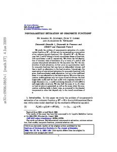
Figure 5: An example of the algorithm’s evolution. The PRTF magnitude in the top left panel is decomposed into resonances (top right panel) and frequency notches (bottom right panel). The bottom left panel shows the evolution of the PRTF spectral envelope from the first iteration to convergence. 3.4. Algorithm evolution example
4.1. Resonances
Figure 5 illustrates the algorithm’s evolution for a particular PRTF. The specific choice of the initial parameters was Nceps = 4, Dmin = 0.1 dB, and ρ = 2. The top left panel illustrates Subject 010 PRTF for an elevation of −45 degrees. The bottom left panel reports the spectral envelope evolution, where we can see how interfering spectral notches negatively influence the initial estimate. The panels on the right represent the resonant (Hres ) and reflective (Href l ) parts of the PRTF at the end of the algorithm. Consider the range where acoustic effects of the pinna are relevant, i.e. the range from 3 to 18 kHz approximately. Figure 5 shows that inside such range the algorithm has produced a realistic decomposition: the gain of the reflective component is unitary outside the notch regions, while the peaks appearing in the resonant component have a good correspondence to Shaw’s modes (this point is further discussed in the next section). Outside the relevant range for the pinna, there is a sharp gain decrease in the resonant part and further imperfections that appear for different subjects and elevations. Nevertheless, this is not a problem as long as we consider the pinna contribution to the HRTF alone. The behavior exemplified in figure 5 is observed for different elevations and subjects too.
The 3-D plots in Figure 6 represent the resonances’ contribution at all available elevations for Subjects 010 and 165, respectively. Every resonance’s center frequency was extracted through an identification system based on a sixth-order ARMA model [15] and spatially tracked along all elevations, resulting in the dotted tracks superposed on the plots. Two brighter areas can be distinctly identified. The first one, centered at around 4 kHz, spans all elevations in both plots and appears to be very similar amongst all subjects in the CIPIC database. Given such observation, it can be immediately noticed that this area contains Shaw’s omnidirectional mode 1. Its bandwidth apparently increases with elevation; however, inspection of the dotted tracks reveals that a second resonance is likely to interfere within this frequency range, in particular Shaw’s resonant mode 2 which appears at around 7 kHz with a magnitude of 10 dB. The second bright area differs amongst subjects both in shape and magnitude. Still, it is most prominent at low elevations between 12 and 18 kHz, a frequency range which is in general agreement with Shaw’s horizontal modes 4, 5, and 6. Note that the magnitude response around 12 kHz takes negative values at high elevations, especially for Subject 010: such an incongruity may be explained by phenomena other than reflections or resonances, e.g. diffraction around the pinna. One may make the same observation for very low and very high frequency zones; nevertheless, these anomalies are most likely due to computational limitations and lie whatever fairly outside the frequency range that interests the pinna. Finally, note that the resonance at ∼ 12 kHz to that at ∼ 7 kHz (associated to mode 2) are excited in mutually exclusive elevation ranges. This effect, which appears for all the analyzed subjects and is especially evident for Subject 165 in Fig. 6(b), gives the
4. RESULTS This section discusses the PRTF features identified through the decomposition carried out by our algorithm. In order to facilitate comparison with previous works, we report results for the same CIPIC subjects that appear in [9] and [14], specifically Subjects 010, 048, 134, and 165. Subject 165 is a KEMAR head with small pinnae.
DAFX-5
Proc. of the 13th Int. Conference on Digital Audio Effects (DAFx-10), Graz, Austria , September 6-10, 2010
Subject 010 − Left PRTF − Notches
Subject 010 − Left PRTF − Resonances
0
20 20
20
15
18 16
−5
18
10
−10
16
5
14
14
−15
f (kHz)
f (kHz)
0 12 −5 10 −10
8
−20 10
6
4
−20
4
2
−25
2
−30
0
0
−40
−20
0
20 40 Elevation (deg)
60
80
−25
8
−15
6
12
−30 −35
−40
−20
0
20 40 Elevation (deg)
(a) Subject 010.
60
80
(a) Subject 010. Subject 048 − Left PRTF − Notches
Subject 165 − Left PRTF − Resonances
0
20 20
20
15
18
−5
18
10
16
−10
16
5
14
14
−15
12
f (kHz)
f (kHz)
0 −5 10 −10
8
12 −20 10
6
4
−20
4
2
−25
2
−30
0
−40
−20
0
20 40 Elevation (deg)
60
80
−25
8
−15
6
0
−40
−30 −35
−40
−20
0
20 40 Elevation (deg)
60
80
−40
(b) Subject 165.
(b) Subject 048.
Figure 6: Resonance plots of two subjects at all available elevations. Dotted tracks highlight resonances’ center frequencies.
Figure 7: Spectral notch plots of two subjects at all available elevations.
impression of a smooth transition from one resonance to the other, and allows us to look forward to a three-resonance filter design.
order to track the effective notch patterns along elevations, discarding the weak ones together with those which appear occasionally. An adequate solution to this problem may reside in the well-known McAulay-Quatieri partial tracking algorithm [16], where spectral notches take the role of partials and elevation dependency replaces temporal evolution.
4.2. Frequency notches As already mentioned, reflection patterns depend strongly on elevation and pinna shape. In general it can be stated that, while PRTFs generally exhibit poor notch structures when the source is above the head, as soon as elevation decreases the number and depth of frequency notches grows to an extent that varies between subjects. These remarks can be immediately verified in Figure 7, where the spectral notches’ contribution for Subjects 010 and 048, respectively, are reported. In particular, Subject 048 exhibits at low elevations a clear reflection structure with three prominent notches. Straightforward comparison of Figure 7(a) to the findings by Raykar (Figure 11(a) in [9]) shows an encouraging correspondence between notch structures. Still, robust techniques are required in
4.3. PRTF re-synthesis Having verified the verisimilitude of the resonance/notch decomposition, we propose a structural model for the pinna. Full parametrization of the model on anthropometrical measurements is needed in order to have complete control of the filter parameters. This means that a resonance/notch mapping has to be defined, e.g. through regression upon a limited set of physical measures. However, this goes beyond the scope of the current paper; for the moment we shall present the re-synthesis procedure from the extracted decomposition of a particular PRTF. Our aim is to design two filter blocks, one for resonances and one for reflections. The general model can
DAFX-6
Proc. of the 13th Int. Conference on Digital Audio Effects (DAFx-10), Graz, Austria , September 6-10, 2010
Resonant Block
Reflection Block
Subject 010 − Left PRTF − Elevation: −23 deg
BP Filter
20 original PRTF synthetic PRTF
15 10
Figure 8: Structure of the general model for the reconstruction of PRTFs. Magnitude (dB)
5
be seen in Figure 8. In Section 4.1 we have shown that a PRTF at one specific elevation includes three main resonances. We can then deduce center frequency and bandwidth of each resonance directly from |Hres | and use these parameters to design three second-order bandpass filter which approximate the effective resonances. An adequate filter block has the three bandpass filters in parallel. Note that the higher resonance may be perceptually irrelevant since it lies near the upper limit of the audible range. We could then consider two resonances only and consequently simplify this block; nevertheless, psycho-acoustical criteria are needed to justify such simplification. For what concerns the reflection block, we imitate the analysis algorithm over |Href l | and proceed as in Sections 3.2 and 3.3 in order to produce a multi-notch filter. A stricter amplitude threshold for notches is considered, and no reduction factor is used (ρ = 1). Each notch in the spectrum of Href l is then characterized by parameters fC , D, and fB , which are feeded to the multi-notch filter construction procedure. Since the order of the resulting filter will be twice the number of considered notches, the amplitude threshold specification turns out to be critical in real-time scenarios. We currently set it to 3 dB. Finally, since the effects of the PRTF are limited to the frequency range 3 − 18 kHz, we are free to cascade a bandpass filter which cuts undesired frequencies to the whole structure. This step would become fundamental if we wanted to integrate the PRTF model with a HAT model. Figure 9 reports the comparison between original and synthesized PRTF magnitudes for three different subjects and elevations. Adherence rate to the original PRTFs varies from case to case. For instance, while in Figure 9(c) and, to a lesser extent, in Figure 9(a) the re-synthesized PRTFs closely follow the original PRTFs’ peaks and valleys, Figure 9(b) evidences a systematic underestimation of resonances. Such effect is due to the high number of deep frequency notches that appear at low elevations, for which our multinotch filter construction procedure turns out to be inadequate. As a matter of fact, interfering bandwidths results in underestimating resonances by several dBs. Using a reduction factor ρ (or a different multi-notch filter design which gives prominence to the bandwidth specification) during re-synthesis would grant a better rendering of resonances, to the detriment of notch depth accuracy.
0 −5 −10 −15 −20 −25 −30
0
5
10 f (kHz)
15
20
(a) Subject 010, elevation -23 deg. Subject 048 − Left PRTF − Elevation: −34 deg 20 original PRTF synthetic PRTF
15 10
Magnitude (dB)
5 0 −5 −10 −15 −20 −25 −30
0
5
10 f (kHz)
15
20
(b) Subject 048, elevation -34 deg. Subject 134 − Left PRTF − Elevation: 6 deg 20 original PRTF synthetic PRTF
15 10
Magnitude (dB)
5 0 −5 −10 −15
5. CONCLUSIONS AND FUTURE WORK
−20
In this paper we presented an approach for estimating and modeling pinna-related transfer functions. We implemented an algorithm that separates the resonant and reflective parts of the PRTF spectrum and used such decomposition to re-synthesize the original PRTF through a low-order filter model. Results showed an overall suitable approximation to the original PRTFs. Ongoing and future work includes: • improvements in the analysis algorithm, in particular through
−25 −30
0
5
10 f (kHz)
15
20
(c) Subject 134, elevation 6 deg.
Figure 9: Original vs Synthetic PRTF plots for three subjects at three different elevations.
DAFX-7
Proc. of the 13th Int. Conference on Digital Audio Effects (DAFx-10), Graz, Austria , September 6-10, 2010 the use of a better multi-notch filter design;
for the development of customizable spatial audio models,” WSEAS Transactions on Signal Processing, vol. 2, no. 11, pp. 1465–1472, 2006.
• tracking of frequency notches through the McAulay-Quatieri partial tracking algorithm, in order to obtain a robust and continuous representation of frequency notches along elevation;
[8] N. Gupta, A. Barreto, and M. Choudhury, “Modeling head-related transfer functions based on pinna anthropometry,” in Proc. of the Second International Latin American and Caribbean Conference for Engineering and Technology (LACCEI), Miami, FL, USA, 2004.
• performing regression of PRTF data over anthropometrical measurements towards functional representation of resonances and notches;
[9] V. C. Raykar, R. Duraiswami, and B. Yegnanarayana, “Extracting the frequencies of the pinna spectral notches in measured head related impulse responses,” J. Acoust. Soc. Am., vol. 118, no. 1, pp. 364–374, July 2005.
• construction of a low-order model (of the kind in Figure 8) for synthesizing PRTFs directly from anthropometry; • integration of the final model with a Head-and-Torso model. 6. REFERENCES [1] (Lord Rayleigh) J. W. Strutt, “On our perception of sound direction,” Philosophical Magazine, vol. 13, pp. 214–232, 1907. [2] E. C. Durant and G. H. Wakefield, “Efficient model fitting using a genetic algorithm: pole-zero approximations of HRTFs,” IEEE Transactions on Speech and Audio Processing, vol. 10, no. 1, pp. 18–27, 2002. [3] D. J. Kistler and F. L. Wightman, “A model of head-related transfer functions based on principal components analysis and minimum-phase reconstruction,” J. Acoust. Soc. Am., vol. 91, no. 3, pp. 1637–1647, 1992. [4] C. P. Brown and R. O. Duda, “A structural model for binaural sound synthesis,” IEEE Transactions on Speech and Audio Processing, vol. 6, no. 5, pp. 476–488, 1998. [5] V. R. Algazi, R. O. Duda, and D. M. Thompson, “The use of head-and-torso models for improved spatial sound synthesis,” in Proc. 113th Convention of the Audio Engineering Society, Los Angeles, CA, USA, 2002. [6] D. W. Batteau, “The role of the pinna in human localization,” Proc. R. Soc. London. Series B, Biological Sciences, vol. 168, no. 1011, pp. 158–180, August 1967. [7] K. J. Faller II, A. Barreto, N. Gupta, and N. Rishe, “Time and frequency decomposition of head-related impulse responses
[10] E. A. G. Shaw, Binaural and Spatial Hearing in Real and Virtual Environments, chapter Acoustical features of human ear, pp. 25–47, R. H. Gilkey and T. R. Anderson, Lawrence Erlbaum Associates, Mahwah, NJ, USA, 1997. [11] P. Satarzadeh, R. V. Algazi, and R. O. Duda, “Physical and filter pinna models based on anthropometry,” in Proc. 122nd Convention of the Audio Engineering Society, Vienna, Austria, May 5-8 2007. [12] R. V. Algazi, R. O. Duda, D. M. Thompson, and C. Avendano, “The CIPIC HRTF database,” in IEEE Workshop on Applications of Signal Processing to Audio and Acoustics, New Paltz, New York, USA, 2001, pp. 1–4. [13] U. Zölzer, Ed., Digital Audio Effects, J. Wiley & Sons, New York, NY, USA, 2002. [14] P. Satarzadeh, “A study of physical and circuit models of the human pinnae,” 2006. [15] P. A. A. Esquef, M. Karjalainen, and V. Välimäki, “Frequency-zooming ARMA modeling for analysis of noisy string instrument tones,” EURASIP Journal on Applied Signal Processing: Special Issue on Digital Audio for Multimedia Communications, , no. 10, pp. 953–967, 2003. [16] R. J. McAulay and T. F. Quartieri, “Speech analysis/synthesis based on a sinusoidal representation,” IEEE Transactions on Acoustics, Speech, and Signal Processing, vol. 34, no. 4, pp. 744–754, 1986.
DAFX-8