where Fm,θ and Fm,Ï denote the antenna element field pat- terns in elevation and azimuth, and the remaining part of the sum term represents the array factor ...
2016 24th European Signal Processing Conference (EUSIPCO)
Evaluating the Spatial Resolution of 2D Antenna Arrays for Massive MIMO Transmissions Fjolla Ademaj, Martin Taranetz, Markus Rupp Christian Doppler Laboratory for Dependable Wireless Connectivity for the Society in Motion TU Wien, Institute of Telecommunications Gusshausstrasse 25/389, A-1040 Vienna, Austria Email: {fademaj, mtaranet, mrupp}@nt.tuwien.ac.at
Abstract—Massive MIMO has been identified as one of the key technologies for the 5th generation of mobile cellular networks. By utilizing 2D antenna arrays with a large number of antenna elements, it enables to form orthogonal beams towards spatially separated User Equipments (UEs). In this paper we evaluate the channel energy and the average throughput of typical indoor- and outdoor UEs at various heights and distances to the macro site. Our goal is to demonstrate the achievable spatial resolution of the beamforming in vertical direction with large antenna arrays. Existing work on directional beamforming strategies is commonly based on simplistic signal propagation assumptions under LOS conditions. This paper considers a realistic 3D channel model that also accounts for multi-path propagation under NLOS conditions. Our results exhibit the dependency of the achievable spatial resolution on both, the size of the antenna array as well as the channel conditions. They show that depending on whether the UE is located indoors or outdoors, the channel has an opposing impact on the achievable spatial resolution. Index Terms—3D beamforming, spatial resolution, 3GPP 3D channel model, antenna array, elevation, azimuth, massive MIMO, vertical sectorization
I. I NTRODUCTION Recent studies on wireless data traffic exhibit an unabated trend of exponentially growing data traffic on a global scale [1]. In response, the development of the 5th generation of mobile cellular networks (5G) is strongly driven forward by both academia and industry. Although its implementation is still largely under debate, there is already a broad consensus on its requirements. The notorious 1000× challenges are higher data rate, lower-latency and lower energy- and cost [2]. According to [1], one of the so called big three 5G technologies to meet these demands will be massive multiple input multiple output (MIMO). Historically, MIMO techniques have been widely recognized as an effective means of improving capacity and reliability in wireless cellular communications by means of spatial multiplexing and diversity, respectively. Massive MIMO can provide enormous enhancements in spectral efficiency without the need for base station (BS) densification or degrading the power efficiency. Its foreseen role is to provide a high-capacity umbrella in support of underlying tiers of small cells. It is widely agreed that evolving from conventional MIMO to massive MIMO necessitates the use of 2-dimensional (2D) antenna arrays. Existing BSs mostly feature linear horizontal
978-0-9928-6265-7/16/$31.00 ©2016 IEEE
antenna arrays, thus only exploiting the azimuth dimension. The additional control over the elevation dimension, as provided by 2D antenna arrays, enables a variety of new strategies such as full dimension (FD)-MIMO, 3-dimensional (3D) beamforming and vertical sectorization [2], [3]. Tailored vertical beams increase the signal power and reduce interference to User Equipments (UEs) in neighboring cells. A crucial component to enable the investigation of such techniques are channel models that incorporate the elevation dimension. A study on a 3D channel model is currently underway within the 3rd Generation Partnership Project (3GPP) [4]. Existing work on directional beamforming mostly assumes simplistic signal propagation characteristics under line-of-sight (LOS) conditions, where only log-distance dependent path loss is taken into account, while the impact of the channel is omitted [5], [6]. However, the channel will alter the beam and, hence, considerably impact the achievable spatial resolution of the antenna array. Thus, when evaluating 2D antenna arrays, it is important to consider a realistic channel model, that accounts for multi-path propagation under both LOS as well as non line-of-sight (NLOS) conditions. In this paper, we introduce a systematic procedure to evaluate the spatial resolution of 2D antenna arrays in a 3GPP consistent scenario under realistic channel conditions. We evaluate the channel energy and the average throughput of typical indoor and outdoor UEs by means of system level simulations at various heights and distances to the macro site. Our results exhibit the dependency of the achievable spatial resolution on both, the size of the antenna array, i.e., the number of antenna elements, as well as the channel conditions, i.e., either LOS or NLOS. In [7] we presented the implementation of the 3GPP 3D channel model in open source simulation tools, and validated our method with the Vienna LTE-A Downlink System Level Simulator [8]. In [9], we introduced an implementation guideline for reducing the complexity of generating desired and interfering channels, including a comparison of various antenna array geometries and electrical tilt angles. It was concluded that in a full hexagonal grid setup with sectorized Evolved Node Bs (eNodeBs), the effect of the elevation dimension and the focusing of energy by beam steering is paled by the varying UE heights. Consequently, in order to
1995
2016 24th European Signal Processing Conference (EUSIPCO)
eNodeB
0°
UE
hUE
hBS
dUE =150 m
ω2(θs)
...
...
...
...
ωM(θs)
λ/2
dUE =250 m
M={1, 10, 100}
90°
dUE =50 m
ω1(θs)
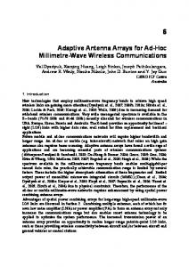
Fig. 1: System model comprising a single eNodeB-sector equipped with a 2D antenna array. Indoor UEs are denoted by green circles, outdoor UEs are indicated by red squares.
explicitly identify the impact of the 3GPP 3D channel on the spatial resolution of a planar antenna array, in this paper we focus on single-eNodeB-sector-single-UE scenarios. II. S YSTEM M ODEL Our scenario comprises a single eNodeB sector and a single UE, as illustrated in Figure 1. The eNodeB-sector is equipped with a 2D antenna array that is mounted at a height hBS and comprises of equidistantly spaced antenna elements in the vertical dimension, as depicted in Figure 2. The horizontal dimension represents the number NTx of antenna ports. The vertical dimension represents the number M of antenna elements mapped to one antenna port. In order to form and steer beams in the analog domain, complex weights ωm , where m denotes the m-th antenna element in the vertical direction, are applied to the antenna elements, as indicated in Figure 2. According to [4, Sec. 7.1], in the vertical dimension, the weights of a beam with main radiation direction θs in elevation are given as 1 2π (1) wm = √ exp (−j (m − 1)dV cos θs ) , λ M where dV is the distance between two antenna elements in vertical direction and λ denotes the wavelength. The angle θs is considered to be 90○ in the direction of the array’s boresight, and has a range of 0○ to 180○ , as indicated in Figure 1. According to the 3GPP urban macro cell (UMa) and urban micro cell (UMi) scenarios, a UE will either be located indoors with a probability of 80%, or outdoors otherwise. The height of an outdoor UE is fixed to 1.5 m, while in the indoor case, the UE can be located at various floors up to a height of 22.5 m. In our evaluation, we separately investigate both typical indoor UEs at a fixed distance from the eNodeB and various heights (blue circles in Figure 1), and typical outdoor UEs at various distances from the eNodeB (red squares in Figure 1). The UE is equipped with linearly-polarized antenna elements with an omni-directional gain pattern, where a single antenna element is associated to a single antenna port r, as illustrated in Figure 2. For modeling the signal propagation between an eNodeB and a UE, we employ the 3GPP 3D channel model [4].
p={1, 2, ..., NTx}
r={1, ..., NRx}
Fig. 2: Antenna array structure at eNodeB consisting of NTx antenna ports and M antenna elements in elevation associated to a single antenna port. At the UE side, a single antenna element is associated to a single port r.
It represents a stochastic geometric channel model and, in comparison to existing models such as the Wireless World Initiative New Radio (WINNER) model, also encompasses the elevation dimension. The model specifies two propagation conditions, LOS and NLOS, respectively. The probability of being in LOS is calculated according to [4, Table 7.2-2] and is separately determined for indoor and outdoor UEs. In the case of indoor UEs, it depends on the height of the UE as well as the break point distance, whereas for the outdoor UE it is only distance-dependent. The break point distance characterizes the gap between transmitter and receiver at which the Fresnel zone is barely broken for the first time [10]. Note that in the context of indoor UEs, LOS and NLOS refer to the signal propagation outside the target building. The channel coefficients are generated for each transmitterreceiver antenna port, and already encompass the antenna element field pattern, the location vector of each element, and spherical unit vector in azimuth and elevation. They are generated for each cluster n and ray l within the cluster, which represents the scattering effect. In the case of NLOS transmission, the channel coefficients for transmit antenna port p and receive antenna port r are given as √ T Pn F (θ ,φ ) hn,l,r,p = [ r,θ n,l,ZOA n,l,AOA ] L (KR + 1) Fr,φ (θn,l,ZOA , φn,l,AOA ) √ ⎡ −1 exp (jΨθφ )⎤ ) exp (jΨθθ Kn,l ⎢ n,l n,l ⎥ ⎢ ⎥ (2) √ ⋅⎢ ⎥ φθ φφ −1 ⎢ Kn,l exp (jΨn,l ) ⎥ exp (jΨ ) n,l ⎣ ⎦ Fp,θ (θn,l,ZOD , φn,l,AOD ) ⋅[ ], Fp,φ (θn,l,ZOD , φn,l,AOD ) where Fr,θ and Fr,φ are the field patterns in the direction of the spherical basis vectors, with θ denoting the elevation direction and φ refers to the azimuth direction. The expressions Fp,θ and Fp,φ are the corresponding field patterns of transmit antenna port p. The terms Kn,l represents cross polarization power ratios for each cluster n and ray l, and Ψn,l are random initial phases for four different polarization combinations. In the LOS
1996
2016 24th European Signal Processing Conference (EUSIPCO)
0
25
120
20
TABLE I: Simulation setup 30
Parameter Carrier frequency LTE bandwidth eNodeB transmit power Antenna element gain pattern Polarized antenna modeling eNodeB antenna polarization Maximum antenna element gain Vertical antenna element spacing Horizontal antenna element spacing UE antenna gain pattern UE antenna array polarization UE speed Receiver type Channel knowledge Feedback delay Noise power density LTE transmission mode Scheduler Traffic model
15 150
5
M=1 M=10 M=100
180
60
10
90
210
120
240
150 180
Fig. 3: Antenna array radiation pattern at eNodeB in elevation dimension, consisting of a single port p with M={1,10,100} elements in vertical direction.
case, the channel coefficients encompass only a single LOS ray. Consequently, the off-diagonal elements in the second matrix of (2) are omitted. The antenna field pattern at port p comprises the beam weights applied to each antenna element. It is given as M
T ¯ rm dm )) Fm,θ (θ, φ) , Fp,θ (θ, φ) = ∑ wm exp (j2πλ−1 0 (ˆ m=1 M
T ¯ rm dm )) Fm,φ (θ, φ) , Fp,φ (θ, φ) = ∑ wm exp (j2πλ−1 0 (ˆ m=1
(3) where Fm,θ and Fm,φ denote the antenna element field patterns in elevation and azimuth, and the remaining part of the sum term represents the array factor (AF). Figure 3 depicts antenna field patterns for M = {1, 10, 100} antenna elements in the vertical direction. The main radiation direction of these patterns can be controlled by the steering angle θs in (1). III. S IMULATIONS In this section, we evaluate the introduced setup by means of system level simulations. As a simulation tool, we employ the Vienna LTE-A system level simulator [11]. We measure both the average UE throughput performance as well as the received channel energy, which we determine by means of the squared NTx NRx
Frobenius norm. It formulates as ∣∣H∣∣2F = ∑ ∑ ∣kp,r ∣2 , p=1 r=1
where NTx refers to the number of transmit antenna ports, NRx is the number of receive antenna ports and kp,r denotes the channel coefficient of transmit antenna port p and receive antenna port r, after performing a fast Fourier transform (FFT) over the channel impulse response from (2). More details for the channel transfer function derivation can be found in [9]. With the received channel energy parameter we measure the received energy in the analog domain, while the average UE throughput is evaluated in the digital domain and extracted from system-level simulations. Hence, in the analog domain
Value 2 GHz 10 MHz 46 dBm 3D pattern [4, Tab. 7.1-1] model 2 [4, Sec. 7.1.1] linear 8 dBi λ/2 λ/2 omni-directional linear 5km/h zero forcing perfect 3 TTI −174 dBm/Hz 4 proportional fair full buffer
we are able to measure the spatial resolution of sharp beams considering the impact of elevation dimension, whereas in the digital domain the output is generated per antenna port. Note that we map M antenna elements in vertical direction to a single antenna port (see Figure 2). Thus we are restricted to the maximum number of antenna ports, which in the current LTE-standard is NTx = 8. A possible solution to introduce the vertical dimension in the digital domain is to apply 2D precoders, however this method is currently under investigation and will be part of a future work. We employ the channel parameters from a 3GPP 3DUMa scenario as specified in [4, Table 7.3-6] and use an NRx × NTx = 4 × 2 antenna port configuration, which is also utilized as a reference setting for calibrations [4, Table 8.2-2]. Note that in this paper we omit the results for a 3GPP 3D-UMi scenario due to space limitations, since they lead to quantitatively similar conclusions. At the eNodeB we consider a 2D antenna array mounted at a height hBS = 25 m, and scrutinize three scenarios with M = {1, 10, 100} antenna elements per antenna port. The radiation pattern of a single antenna element is given by a combination of a vertical and a horizontal antenna element pattern, as specified in [4, Tab.7.11.]. At the UE, a linear array, consisting of two horizontal elements is considered. The target building of the indoor UE is assumed to be located at a distance dUE = 150 m away from the eNodeB. This distance refers to the center of a typical macro-cell [4]. We consider user heights of hUE = {1.5, 10.5, 22.5} m, corresponding to ground floor, middle and top floor of the building, respectively. The outdoor UE is considered at distances dUE = {50, 150, 250} m away from the eNodeB, referring to three regions in the cell, near zone, cell center and cell-edge, respectively. The simulation parameters are summarized in Table I. The simulation results exhibit a high information density. In the following, we only focus on the most important insights due to space limitations. Figure 4 provides simulation results in terms of received
1997
2016 24th European Signal Processing Conference (EUSIPCO)
Average UE throughput [Mbit/s]
Channel energy [dB]
-80
M=1 M=10 M=100
-90 -100 -110 -120 -130 -140 -150 0
20
40
60
80
100
Average
LOS
NLOS
120
140
Steering angle θs [°]
160
180
80 70 60 50 40 30 20 M=1 M=10 M=100
10 0
0
20
40
60
-100 -105 -110 -115 -120 -125 -130 -135 40
60
80
100
120
140
Steering angle θs[°]
(c)
160
180
Average UE throughput [Mbit/s]
h=1.5 [m] h=10.5 [m] h=22.5 [m]
-95
20
100
120
140
160
180
140
160
180
(b)
-90
-140 0
80
Steering angle θs[°]
(a)
Channel energy [dB]
channel energy and average UE throughput measured in [Mbit/s], as evaluated for typical indoor UEs. The received channel energy is normalized to 1 Joule on a dB scale. Figure 4a shows the received channel energy for M = {1, 10, 100} antenna elements in elevation, while the UE height is fixed at hUE = 1.5 m, i.e., the lower floor of the building. It is observed that the antenna array geometry in elevation impacts LOS and NLOS cases in a distinct manner. For the steering angle θs = 100○ , which represents the case where the main radiation beam is directed toward the UE location, increasing the number M of antenna elements in elevation monotonically increases the channel energy only when the UE is in LOS. Increasing M from 1 to 10 results in 10 dB enhancement, while for M = 100 results in 4 dB enhancement compared to M = 10. Hence, a ten-fold increase in M does not result in a ten-fold increase in ∣∣H∣∣2F . For the NLOS case the highest channel energy is received for M = 10. In terms of average performance between LOS and NLOS, increasing the antenna array size from M = 10 to M = 100 results in no difference in terms of received channel energy, at θs = 100○ . Remarkably, the spatial resolution between two neighbor steering angles, θs = 100○ and θs = 110○ , results in 20 dB decrease for M = 100 and 10 dB decrease for M = 10 in both LOS and NLOS case. Although the LOS case would achieve a large resolution, it only appears in 20 % of the cases. Hence, the average performance is dominated by the performance under NLOS conditions. Figure 4b provides the performance results in terms of average UE throughput for the same system configuration. A setup with M = 10 achieves the highest throughput, when the steering angle aims at the UE location. Remarkably, with M = 100, the performance is consistently lower than with M = 10. This indicates that a resolution of 10○ is not sufficient to achieve close to peak performance, which is expected when the beam exactly aims into the direction of the UE. Observing the LOS case and a steering angle of θs = 100○ , a similar performance is obtained for all investigated values of M . Figure 4c shows the received channel energy for UE heights of hUE = {1.5, 10.5, 22.5} m and an antenna array with M = 10 elements in elevation. The results indicate that, on average, the largest energy is received at hUE = 22.5 m, which is mainly due to the large likelihood of the UE being in LOS. According to [4], the probability of being in LOS is 0.5 at this UE location. Due to the different UE heights, the peaks of the channel energy are obtained at different steering angles. Furthermore, the results indicate the impact of the building blockage. More specifically, when the target building is in NLOS, the energy decreases at lower user heights and the resolution between different steering angles becomes less sharp. For the same configuration, the results in terms of average UE throughput are provided in Figure 4d. As expected, for hUE = 22.5 m, the difference in throughput performance between LOS and NLOS is smaller than at lower heights. Interestingly, at hUE = {1.5, 10.5} m in NLOS, the resolution between different steering angles is much sharper than in the LOS case. Remarkably, for NLOS transmissions, despite
80 70 60 50 40 30 h=1.5 [m] h=10.5 [m] h=22.5 [m]
20 10 0
20
40
60
80
100
120
Steering angle θs[°]
(d)
Fig. 4: Channel energy (a) (c) and average throughput [Mbit/s] (b) (d) of typical indoor UE over steering angle. Results are shown for M = {1, 10, 100} antenna elements in elevation at a fixed user height of hUE = 1.5 m and for various UE heights of hUE = {1.5, 10.5, 22.5} m at M = 10. Vertical black lines denote 95 % confidence intervals. showing a more moderate resolution in terms of channel energy, the channel amplifies the distinction between two neighboring angles in terms of throughput. Figure 5 provides the simulation results for typical outdoor UEs. Figure 5a shows the received channel energy for M = {1, 10, 100} antenna elements in elevation, while the UE distance from the eNodeB is fixed at 150 m. The energy difference between LOS and NLOS conditions exhibits a similar behaviour as in the indoor case, while the absolute energy is higher. This is partly due to the fact that the outdoor UEs do not experience wall penetration loss. In addition, the received channel energy experiences a larger decay from the center steering angle of 90○ towards neighboring points. Especially for the LOS transmission, the resolution between neighboring steering angles is larger. Figure 5b provides the performance results in terms of average UE throughput for the same system configuration. Remarkably, in comparison to indoor UEs, the throughput performance under LOS conditions for various numbers M of antenna elements is invariant with respect to the steering angle. Moreover, under NLOS conditions, the resolution between neighboring steering angles is less distinct. The average performance resembles the performance under NLOS conditions, which is the dominant state for a UE at dUE = 150 m. Figure 5c shows the received channel energy of outdoor
1998
M=1 M=10 M=100
Channel energy [dB]
-60 -70 -8 0 -9 0
-100 -110 -120 -130 0
20
40
60
80
100
120
140
Steering angle θs[°]
160
Average UE throughput [Mbit/s]
2016 24th European Signal Processing Conference (EUSIPCO)
80 75 70 65 60 55 M=1 M=10 M=100
50 45 0
180
20
40
60
d=50 [m] d=150 [m] d=250 [m]
-60
Channel energy [dB]
-70 -80 -90
-100 -110 -120 20
40
60
80
100
120
140
160
180
(b)
100
120
140
Steering angle θs[°]
160
180
Average UE throughput [Mbit/s]
(a)
-130 0
80
Steering angle θs[°]
energy is more focused than in the outdoor case, both under LOS and NLOS conditions. Particularly, for outdoor UEs in LOS, we did not observe any spatial resolution in terms of throughput. This indicates that even the wall penetration loss affects the achievable spatial resolution of vertical beamsteering. We further found that while the spatial resolution as imposed by the antenna array pattern itself is amplified for indoor UEs, it is paled for outdoor UEs. The fact that our results hamper the derivation of further simple rules of thumb should raise awareness on the distinct impact of the channel on both indoor and outdoor transmissions, especially under NLOS conditions.
80
ACKNOWLEDGEMENTS
75 70
This work has been funded by A1 Telekom Austria AG, and the KATHREIN-Werke KG. The financial support by the Federal Ministry of Economy, Family and Youth and the National Foundation for Research, Technology and Development is gratefully acknowledged.
65 60 55 50
d=50 [m] d=150 [m] d=250 [m]
45 40 0
20
40
(c)
60
80
100
120
140
Steering angle θs[°]
160
180
(d)
R EFERENCES
Fig. 5: Channel energy (a) (c) and average throughput [Mbit/s] (b) (d) of typical outdoor UE over steering angle. Results are shown for M = {1, 10, 100} antenna elements in elevation at a fixed user distance of dUE = 150 m and for various UE distances of dUE = {50, 150, 250} m at M = 10. Vertical black lines denote 95 % confidence intervals. UEs at distances dUE = {50, 150, 250} m and a fixed antenna array geometry with M = 10 antenna elements in elevation. Due to the distances, the peak values are located at different steering angles. As opposed to typical indoor UEs, the spatial resolution is now less sharp than the AF itself. Hence, the effect of the spatial resolution is paled by the channel itself. For the same configuration, the results in terms of average UE throughput are provided in Figure 5d. As expected, dUE = 50 m is largely dominated by the LOS case. Remarkably, the throughput in the LOS case is again invariant with respect to the steering angle for all user distances dUE , i.e., even at cell-edge. This is a particularity of the outdoor case and indicates that the indoor case is severely impacted by the wall penetration loss. The spatial resolution due to different steering angles is only observed under NLOS conditions and dUE = {150, 250} m. IV. C ONCLUSION This work presented a systematic procedure to evaluate the spatial resolution of 2D antenna arrays under realistic channel conditions. We established single-eNodeB-sector single UE scenarios, and demonstrated the differences in terms of received channel energy and average throughput for indoor- and outdoor UEs at different UE heights and distances from the eNodeB. The results indicate that the antenna array geometry in elevation impacts LOS and NLOS cases in a distinct manner. We observed that for typical indoor UEs, the channel
[1] J. Andrews, S. Buzzi, W. Choi, S. Hanly, A. Lozano, A. Soong, and J. Zhang, “What will 5G be?” IEEE Journal on Selected Areas in Communications, vol. 32, no. 6, pp. 1065–1082, June 2014. [2] E. Larsson, O. Edfors, F. Tufvesson, and T. Marzetta, “Massive mimo for next generation wireless systems,” IEEE Communications Magazine, vol. 52, no. 2, pp. 186–195, February 2014. [3] Y. Song, X. Yun, S. Nagata, and L. Chen, “Investigation on elevation beamforming for future LTE-Advanced,” in IEEE International Conference on Communications Workshops (ICC), June 2013, pp. 106–110. [4] 3rd Generation Partnership Project (3GPP), “Study on 3D channel model for LTE,” 3rd Generation Partnership Project (3GPP), TR 36.873, Sept. 2014. [5] M. Soszka, S. Berger, A. Fehske, M. Simsek, B. Butkiewicz, and G. Fettweis, “Coverage and capacity optimization in cellular radio networks with advanced antennas,” in Proceedings of WSA 2015 in 19th International ITG Workshop on Smart Antennas, March 2015, pp. 1–6. [6] A. Tall, Z. Altman, and E. Altman, “Virtual sectorization: Design and self-optimization,” in 2015 IEEE 81st Vehicular Technology Conference (VTC Spring), May 2015, pp. 1–5. [7] F. Ademaj, M. Taranetz, and M. Rupp, “Implementation, validation and application of the 3GPP 3D MIMO channel model in open source simulation tools,” Twelfth International Symposium on Wireless Communication Systems, ISWCS 2015. [8] http://www.nt.tuwien.ac.at/research/mobile-communications/ vienna-lte-a-simulators/. [9] F. Ademaj, M. Taranetz, and M. Rupp, “3GPP 3D MIMO Channel Model: A Holistic Implementation Guideline for Open Source SImulation Tools,” EURASIP Journal on Wireless Communication Networks 2016. doi:10.1186/s13638-016-0549-9. [10] H. Masui, T. Kobayashi, and M. Akaike, “Microwave path-loss modeling in urban line-of-sight environments,” IEEE Journal on Selected Areas in Communications, vol. 20, no. 6, pp. 1151– 1155, Aug 2002. [11] M. Taranetz, T. Blazek, T. Kropfreiter, M. K. M¨uller, S. Schwarz, and M. Rupp, “Runtime precoding: Enabling multipoint transmission in LTE-Advanced system-level simulations,” IEEE Access, vol. 3, pp. 725–736, 2015.
1999