(COM) components. This paper will review software programming issues and the use of Microsoft COM in the development of machine control components.
Proceedings of the World Automation Congress (WAC) 2002, as part of the International Symposium on Robotics and Applications (ISORA), Orlando, FL, June 9-13, 2002.
Evaluation of Component-Based Reconfigurable Machine Controllers Sri Kolla Department of Electrical Engineering, Bowling Green State University, USA
John Michaloski and William Rippey National Institute of Standards and Technology, Gaithersburg, MD, USA
ABSTRACT The lack of interoperability and integration standards is severely hindering manufacturing productivity. To address this problem, a General Motion Control (GMC) Testbed has been developed at National Institute of Standards and Technology (NIST) with one of its goals to validate the Open Modular Architecture Controller (OMAC) interface specification for reconfigurable, plug-and-play open-architecture controllers. The GMC validation testbed was built using Microsoft Component Object Model (COM) components. This paper will review software programming issues and the use of Microsoft COM in the development of machine control components. Strategies and tests of COM programming for a controller will be discussed. KEYWORDS: open architecture, Finite State Machine, component, module, control, standard, motion, machine
INTRODUCTION The increasing pressures on manufacturers to improve time to market and integrate the shop floor directly into the enterprise business systems places a premium on better techniques to design, integrate, test, evaluate, and later reconfigure control systems. Lost time and money in manufacturing systems integration, testing, and installation is profound. The Manufacturing Execution Systems Association (MESA) estimates that for every dollar spent on software, an additional $4 is required to install and integrate it. [3] The 1999 Robotics Industry Forum estimates that integration and deployment of robot systems typically cost 3 to 5 times the cost of the robot itself. The root of the problem can be traced to the lack of interoperability. NIST has long been committed to helping industry improve interoperability and systems’ integration through standards participation. [4,6] In the area of motion-based control systems, the NIST Intelligent Systems Division has developed a General Motion Control (GMC) testbed to conduct a variety of development, safety, integration and performance evaluations. One area of research within the NIST GMC testbed is to assess the efficacy of component-based technology in controller design and development. This paper will discuss preliminary
Modules
Application System System Coordinator Coordinator n
Domain Domain Coordinator Coordinator
n
Components
Omac Oma n IOmac Module Modul
n
Control Control Law Law
HMI HMI Axis Group Group Axis
ITask ITask
IProgram IProgram
Process Process Model Model
Axis Axis Kinematics Kinematics Model Model
Task Task Coordinator Task Coordinator
Legend
Inheritence
IO IO Device Device
Aggregation
n
IO Point Point IO
Discrete Discrete Logic Logic
Navigability
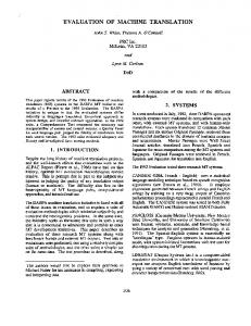
Figure 1. OMAC API UML Abstraction Hierarchy results from the validation of the Open Architecture Modular Controller (OMAC) Application Programming Interfaces (API) component-based specification. The OMAC API, developed under the auspices of the OMAC Users Group [9], tackles the more complex open architecture controller requirements –plug-and-play, reconfigurability, extensibility, and reusability – by means of component-based technology. The paper will start by reviewing the OMAC API. A brief overview of the NIST GMC testbed hardware and software will be given. The Microsoft Component Object Model (COM) and related software development strategies will be discussed. Empirical observations concerning COM and OMAC API control component development will be given (see [1] for observations on effective COM development in general). OMAC API Overview The OMAC API specification contains machine control APIs, as well as a formal API to address the integration and collaboration of components. Figure 1 shows a Unified Modeling Language (UML) [10] hierarchy diagram of the OMAC API. OMAC API uses several terms to differentiate component concepts. The term “Component” applies to any reusable piece of software, while the term “Module” refers to a aggregating of components. The term “Task” is applied to a type of component that encapsulates programmable behavior containing a series of steps, running to completion that may be rerun. OMAC API modules shown in Figure 1 include the following. Axis handles servo motion control. Axis Group coordinates multiple axes motions. Task Coordinator handles sequencing of operations. Input-Output (IO) Device manages communication between the physical hardware device and IO software, and is responsible for managing a group of IO points. Human Machine Interface (HMI) coordinates human interaction with a controller.
Discrete Logic handles IO programming. Domain Coordinator creates OMAC components for a single address space. System Coordinator manages a set of Domain Coordinators. OMAC API components shown in Figure 1 include the following. Control Law calculates servo loop setpoints. IO Point provides typed (e.g., long, scaled) reading or writing of physical or logical data points. Kinematics Model handles geometrical properties of motion. Process Model integrates sensor data and control. A major goal of the OMAC API is to leverage mainstream, high-volume, component technology. Hence, the current OMAC API specification is defined using Microsoft Interface Definition Language (MIDL) – the basis for COM. Adoption of the OMAC API specification would allow control vendors to supply standard components that machine suppliers could then easily configure and integrate to build machine control systems. Additionally, end-users would then be able to easily reconfigure these systems based on evolving system requirements. The OMAC API also contains introspective component properties to improve developer maintenance and diagnostics, plus allowing components to be used at design time in an Integrated Development Environment (IDE) as well as runtime. NIST GMC TESTBED SYSTEM DESIGN To develop a motion control testbed representative of a broad range of factory floor operations, the testbed focus was on automation markets eager for advances in component integration and interoperability. The focus was on packaging applications since they require high accuracy, high-speed regulation, and rapid changeover between product lines. The packaging industry is undergoing a design transformation, moving from mechanical control solutions using gears, cams, and chains, to electronic solutions using servomotors and software control. Hardware The NIST GMC testbed includes a variety of equipment found in packaging and other manufacturing factory floor operations. The testbed was built from commercial-off-theshelf automation equipment and general-purpose computers. Networked IO was a testbed requirement as it lowers costs from common wiring and communication protocol. The initial NIST GMC testbed packaging application was to control a bottle conveyor and perform various quality checks as the bottles moved along the conveyor. DeviceNet was selected as the network communication protocol, since it is an international device-level IO standard (e.g., IEC 62026/3) with a wide-variety of supporting equipment. The testbed system design includes two positioning servo drives with a DeviceNet interface for digital positioning control of brushless servomotors, used to power the conveyor chain. The servomotors provide higher precision control of chain speed. The DeviceNet IO equipment in the testbed includes: 1) a general-purpose modular discrete IO with 4 inputs and 4 outputs, 2) several binary IO modules and wiring blocks, and 3) a 4 color stack light IO module to color code for displaying machine status. IO modules of different personalities interlock so that the communications adapter can access device information and make it available over DeviceNet. These IO modules were wired to accept simple contact switches as well as 3-wire electronic proximity and photoelectric sensors.
NIST GMC TESTBED SOFTWARE DESIGN The thrust of the NIST GMC testbed was to evaluate the development, integration and maintenance performance using Microsoft COM. [7] This emphasis on COM resulted in an initial soft-real-time development platform based on Windows NT/2000. Components developed under Windows NT/2000 can in theory run under Window/CE, which is a hard-real-time operating system. Real-time control issues using Microsoft operating systems are addressed in [2,11]. The suitability of COM for motion control, given its inherent complexity and original design for business applications, were a primary research issue. Issues such as ease of programmability, diagnostic capabilities, and overall performance were also considered. Microsoft COM COM is a component technology that allows objects to interact within a single process or across process and machine boundaries. The only way to manipulate the data associated with an COM object is through an interface on the object. The NIST GMC testbed developed a suite of COM components based on the OMAC API specification, while varying aspects of the OMAC API specification that were substandard. The inhouse NIST GMC components were developed using Microsoft Visual C++, which includes many programming tools to simplify COM component development. Using programming environments other than Visual C++ to build COM components is possible; but no consideration was given to this aspect during the initial testbed development. In addition, most in-house COM components were “local”, where the COM interface implicitly supplies a thin layer of abstraction on top of a Dynamically Linked Library and requires little overhead or performance penalty after loading. One benefit of COM is the ability to determine supported and optional functionality through the QueryInterface method required of all COM components. The use of aggregated component interfaces coupled with the success or failure of the QueryInterface method on these interfaces provides a systematic approach to determining if an interface is supported. This capability determination meant that not all functionality was required of each component. We did require that each component support a common OMAC interface to allow naming, state, diagnostics, and configuration information to be available from all components. One major disadvantage of COM is that the lifetime of a component is determined by reference counting with a component being deleted when its reference count is zero. Adhering to the COM pointer reference paradigm is daunting; with mismanaged pointer management potentially causing components to suddenly “disappear”. During development, there was a concern that COM would be too memory-intensive since some motion programs could contain thousands of very small trajectory increments. We ran a memory test to see how many motion segment COM components, each corresponding to a step in a program, could be created before having the PC run out of virtual memory. The test created more than 23 thousand COM motion segments of roughly 2K in size on a Windows NT platform with 520M of virtual memory before failing. The result is approximate wherein results would vary based on program size and amount of system virtual memory. More troubling was the infamous PC blue screen of death that resulted upon exhausting virtual memory.
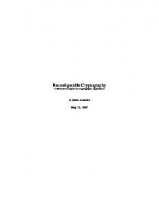
State Machine Logic Finite State Machine (FSM) control logic is pervasive throughout the OMAC API. The OMAC API defines two fundamental FSM – a lifecycle “OMAC” FSM and a “Task” FSM. The lifecycle FSM is used to deploy, publish, connect, initialize and shutdown components during the lifetime of the component. The Task FSM is a “lighter” state logic for running programs and individual program steps. The two basic FSMs are then specialized on a per module/component/task basis. To handle the FSM logic, we developed a C++ FSM class library that could handle state nesting and other advanced state machine logic. [5] The benefits of using FSM logic within the NIST GMC testbed were twofold: improved logical program correctness and eased traceability of program logic. FSM flags can be set within a component to catch program logic errors by “breakpointing” at any deviation from the accepted Figure 2 FSM Diagnostic Playback FSM logic, such as unexpected events or invalid state transition. Hardware faults or other system errors also can be pinpointed and traced to a single step within a FSM. Figure 2 illustrates the NIST GMC testbed controller after an amp fault causes the followingPosition state to transition to a fault state. The arrow (added for this paper) shows the Amp Fault IO point as 1, indicating a fault. The NIST GMC testbed controller saves snapshots of the FSM as well as data dumps at each major state transition so that the sequencing buttons under the FSM display allow forward and reverse playback to “reenact” the error. Employing system-wide FSM logic is especially appealing to the manufacturing industry for faster maintenance and diagnostic troubleshooting. The importance of the FSM benefits of correctness and traceability cannot be understated because integrating diagnostic tools in logic control is considered the number one challenge for manufacturing systems. [8] The primary drawback to strict FSM compliance is agreeing on acceptable component state logic that is neither trivial nor excessively complicated. Template Component Development Component development for motion controllers is laborious, as most components are required to support a full life-cycle of component functionality in addition to its own
control functionality. The NIST GMC testbed employed a number of C++ component templates to accelerate the coding. The C++ template is a complex, but powerful programming mechanism that streamlines repetitive programming aspects. Microsoft aggressively uses templates within its Active Template Language (ATL) as part of Visual C++ that is one of the primary COM programming development tools. ATL and the use of wizards simplify development by automating many of the multifaceted interfaces required of a COM component. ATL is extremely lightweight in that only elements that are required in an application are included, not the complete development library - as is case when using the Microsoft Foundation Class (MFC) Library. One shortcoming to ATL is that it does not implement COM inheritance without the use of “chaining” of interfaces. Although helpful, chained COM objects have difficulty in sharing member variables or common interfaces. We developed C++ inheritance interface templates, but this required a major learning curve to overcome the tricks ATL uses in instantiating COM objects. SUMMARY This paper gives an overview the NIST GMC testbed effort to validate the OMAC API specification. We have some empirical observations concerning this effort. We found the development of common C++ templates to implement COM control components took months to develop, but once available, speeded development and improved component reliability. We found FSM traceability invaluable in solving the number one challenge in manufacturing systems – better program logic diagnostics. The OMAC API validation is still preliminary and there are more tests to run. Ultimately, we would like to test communication and functionality aspects of components with a rigorous set of simulated errors and increasing processor loads to see at what point breakdowns occur. REFERENCES 1. Box, D., Brown, K., Ewald, T., and Sells, C., Effective COM, Addison-Wesley Longman, Reading, Massachusetts, 1999. 2. Cheng, H., Proctor, F.M, and Michaloski J.L., and Shackleford,W.P, “Real-Time Computing in Open Systems for Manufacturing," JCISE: Vol. 1, No. 1, March 2001. 3. Dugenske, Andrew, “The Framework Implementation Project,” CIRCUITS ASSEMBLY, Manhasset, NY, March 2001. 4. Evans, J., Frechette, S., Horst, J., Huang, H., Kramer, T., Messina, E., and Proctor, F., “Analysis of Dimensional Metrology Standards,” NISTIR 6847, National Institute of Standards and Technology, Gaithersburg, MD, December 2001. 5. Finite State Machine Library, www.isd.mel.nist.gov/projects/omacapi/Software 6. Kemmerer, S., “STEP: The Grand Experience,” NIST Special Publication 939, National Institute of Standards and Technology, Gaithersburg, MD, 1999. 7. Microsoft Corporation, “Component Object Model,” http://www.microsoft.com/com 8. NSF Workshop on Logic Control for Manufacturing Systems, University of Michigan, Ann Arbor, June 26-27, 2000. 9. Open, Modular, Architecture Group (OMAC) User’s Group, http://www.arcweb.com/omac/ 10. Rational Software Corporation, UML 1.3 Documentation, www.rational.com/uml 11. Rockwell Automation – Allen Bradley, “Using the Windows NT Operating System for Soft Real-time Control - Separating Fact from Fiction”, White Paper, 1998.