Evolving a Generic Application into a Domain-oriented Design Environment
Anders Mørch Dept. of Information Science, University of Bergen N-5020 Bergen, Norway
[email protected]
This paper presents an approach for how end-users can tailor (and evolve) generic computer applications into domain-oriented design environments. It is proposed as a remedy for inflexible computer applications, and as an alternative to building domain-oriented design environments from low-level building blocks. A typical generic application is a word processor, a drawing program, or an email system developed for a generic task such as writing, creating diagrams, or sending electronic messages; whereas a domain-oriented design environment is an application developed for a specialized task, such as collaborative writing, home planning, or meeting scheduling. End-user tailoring addresses general problems in software reuse and requirements capture. It supports application evolution by a set of tools that are integrated into a generic application. The tools give an end-user access to the parts of the application that have
to be addressed during tailoring. A method for building and integrating the tools is described. How to use the tools to evolve a basic drawing program into a kitchen design environment is given as an example. The paper ends with a general discussion of the approach, and gives suggestions for further work in the area.
1. Introduction Generic applications are computer-based tools that help professional users with recurrent tasks such as writing papers, drawing diagrams, tabularizing data, and sending messages to other people. It is a general held belief in many professions that these tasks are important. The applications supporting the tasks are therefore also important. Generic applications have a peculiar characteristic that makes them different from their predecessor ar-
© Scandinavian Journal of Information Systems, 1996, 8(2):63–90
tifacts, typewriters and electronic calculators: computer applications are richer in functionality and have a greater potential for adaptation. This potential is largely a result of their software nature and has only partly been realized in today’s computer applications. To fully realize this potential and to transcend the hardware analogy to reuse (plugging components into sockets inside a machine), software applications must be adaptable at the user interface by the end-users to fit their needs and the requirements of the organization in which they work. End-user tailoring is defined as the process of making persistent adaptations of a generic application to the local requirements of an end-user organization (Mørch 1995). This article addresses how to support this process. The focus is on how to build technology so that people can adapt the technology to their environment, rather than the other way around. The article is organized as follows: first the general problem motivating this research is described. Then a solution to the problem is proposed, both as a method and a set of tools for doing tailoring. A scenario showing how to use the tools to tailor a generic drawing program is given as an example. It is shown through the example that tailoring is a kind of application evolution: an application, in the hands of one or more users, can evolve from one task-domain to another. An empirical evaluation of the tailoring tools showed that college-level users were able to tailor a generic application at three levels of complexity. The study furthermore confirmed an hypotheses that rationale was useful for comprehension of program code. It also revealed some
shortcomings, including that rationale may be less useful for code that is difficult to understand and hence be of less value for complex systems. A discussion at the end will illuminate some of the strengths and potential weakness in that the of this approach. Future work aims at addressing some of the shortcomings and weaknesses.
2. The problem addressed and related approaches The general problem addressed in this article is software reuse. Software reuse refers to the process of creating software systems from existing systems rather than building them from scratch (Biggerstaff 1989, Fischer 1987, Krueger 1992). Four steps in this process are: (1) locating existing software components, (2) understanding what they do, (3) integrating them with other components, and (4) extending them to create new components. For reuse to be realistic, it should be easier than building a system from scratch. The particular software systems addressed in this project are generic applications. A generic application is typically an off-the-shelf, packaged software product, such as a word processor, a spreadsheet, or a drawing program, but it can also a be custom-made (in-house developed) system where the original requirements have changed, making it incompatible with respect to current needs. Due to the general nature of the tasks supported by a generic application, they are likely to change as the application is being used. This is a consequence of the varying levels of user expertise and as a result of user organizations having dif-
A. Mørch 64
ferent requirements for how to accomplish the tasks. How to adapt an application to better support new tasks and locally defined requirements is the specific problem addressed in this project. The scope of the problem ranges from issues in software engineering and object-oriented programming (software reuse) to issues in human-computer interaction and social aspects of technology use (design, requirements capture, organizational use). This broad scope, I claim, is necessary for a full exposure of the issues that are relevant to end-user tailoring. A disadvantage is that the exposure may at times seem unfocused. I try to overcome a lack of focus by giving references to related work when applicable. The terms application-evolution and end-user tailoring are used synonymously throughout this article. End-user tailoring borrows terminology from human-computer interaction, end-user programming, and object-oriented programming, and this terminology been described in a companion article (Mørch 1995). It is further (more remotely) related to research in artificial intelligence (AI), in particular work on genetic algorithms and evolutionary programming (Angeline 1995). The aim of the AI work is to make a computer system automatically adapt to a surrounding environment. The current work, in contrast to the AI work, gives the end-users first-class status in the evolutionary process by making themselves creators of evolutionary change. This shift in focus (from machine to human intelligence) is inspired by the Scandinavian democratic approach to system development (Bjerknes et al. 1991, Bjerknes et al. 1987,
Greenbaum & Kyng 1991). In most of the Scandinavian countries, the future users of a computer system have the legal rights to participate (or have representatives participate) in the process of designing it. The term “end-user” is therefore a collective term I use for the people (users, groups of end-users, local developers) working in a user organization (consumers of generic applications) as opposed to the people (designers, programmers, support personnel) working in a developer organization to produce the generic applications. End-user tailoring requires tools and techniques for doing tailoring that are available during use. These tools need to be integrated into generic applications during development. Many of today’s applications do have built-in tools for various kinds of tailoring activities. For example, MS Word 6, allows the user to customize the user interface of the word processor by changing views of menus, buttons, and toolbars, and to create new functionality by writing macros in Visual Basic (Figure 1).
3. Method and tools for end-user tailoring Tailoring support is needed when the functionality of a generic application is insufficient, incomplete, or obsolete, or the environment in which the application is being used has changed. The environmental constraints give the requirements for changing the application, and the agent of change is the end-user. Tailoring is therefore initiated by the end-users to continue the design started by the original developers (Henderson & Kyng
A. Mørch 65
FIGURE 1. Creating a customized toolbar for drawing commands in MS Word 6. (1) Selecting the Tools menu from the menu bar, (2) selecting the Customize menuitem to open the Customize window, (3) selecting the Drawing toolbar from this window, and dragging buttons onto a new toolbar at the top.
1
3
2
1991), but delayed by a difference in time and geographical location. The distinction between use, tailoring, and development is “blurry.” This is intentional because I try to extend the technical software engineering perspective towards the use situation. However, there are transitions between the three modes that can be identified, and one of them is caused by a breakdown (Winograd & Flores 1986). A breakdown identifies the transition between use and tailoring (Mørch 1994). Breakdowns are created when the application
can no longer be used for a task the user wishes to perform. For example, when the default column width of a word processor is not the one you want, or the scale command of a drawing program isn’t scaling figures the way you want it to scale, it creates a breakdown for the user. However, a breakdown is not entirely negative (as the term may suggest) since it may leave the user with a handle to serve as an index into the application. This handle (a button on the screen, a menu item, a window), when taken advantage of, can be used to access all the parts of the application that have to be
A. Mørch 66
addressed in order to repair the breakdown. This aspect of tailoring is not well supported in today’s commercial applications. In MS Word 6, for example, tailoring is initiated by going to a separate Tools menu and selecting separate menu items, such as Customize and Macro. A typical sequence of commands needed to accomplish a breakdown repair is shown in Figure 1. This sequence does not create a seamless transition from use to tailoring because the integration of user interface and tailoring tools is coarse-grained. An alternative, finergrained approach must be pursued. This is described next. 3.1. Application unit as the smallest, yet most general building block The graphical user interface (GUI) of a generic application is, from the point of view of a user, composed of graphical presentation objects (windows, menus, buttons, etc.). In a similar way, I propose that the user interface of a tailorable generic application is composed of application units (Mørch 1995a). Application Unit (AU) is the term I use for a reusable software component. It is “deeper” than a GUI component and consists of the following three parts: (1) presentation object (as in a GUI), (2) rationale, and (3) implementation code (for GUI and application code). The first and third parts are “bridged” by the second part (rationale). This is described graphically in Figure 2, and conceptually by the following comparison among the three parts: •
Rationale components and presentation objects are made of the same kind of material (text, pictures, graphics, sound, video, animation).
•
Presentation objects align with the structure of an external task-domain model.
•
Rationale components align with the structure of internal implementation code.
•
Rationale components are different from implementation code in that the rationale is not interpreted or executed by the computer.
FIGURE 2 The triadic structure of application units. The three parts (aspects) in bold-face are accessed by eventhandlers in the user interface. An eventhandler is a computational mechanism that accepts input from the user, such as a mouse-click or a keyboard entry, and passes it on to the application. The relationship between implementation code and rationale has not yet been formally developed.
eventhanPresentation object eventhaneventhan-
Implementation code
eventhan-
Rationale
The conceptual building blocks that have inspired the AU concept are the MVC (Model-View-Controller) triad in Smalltalk (Krasner & Pope 1988), the button-script dyad in HyperCard (Williams 1987), and the VBX custom controls in Visual Basic (Microsoft 1994). However, none of the related approaches have rationale as an integrated part. In two other papers (Mørch 1995a, Mørch
A. Mørch 67
1994), I argue that rationale needs to be integrated at the same basic building block level as the other two parts. This idea was first introduced in the Buttons project (MacLean et al. 1990), but came to an end because it was implemented in an environment that later became obsolete (Xerox InterLisp). The reason for having rationale as a third part at the same granularity as the other two parts is to “fill in” the gap between user interface and implementation code (Mørch 1995a). This makes a gradual transition from use to tailoring possible. With application units as the basic building blocks, this transition is divided into three levels, each level giving an increased amount of tailoring power (Mørch 1995): 1. Using the system by interacting with and customizing presentation objects in the user interface. 2. Understanding the application by reading and designing rationale. Rationale captures the application’s requirements for design and use. Rationale is not interpreted by the computer but meant for human reflection and to aid comprehension of the application. 3. Reading and writing implementation code. New code is added as extensions of old code. The new code is compiled (or interpreted) and executed by the computer. The price of tailoring power is paid at the expense of having to master an increased amount of computational complexity. This is overcome by arranging the levels in steps: mastering one level makes the transition to the next level easier. To make the transition from use to tailoring practical, all the three parts of
an application unit should be accessible from the user interface. To accomplish this, the presentation object (P-object) of an AU serves as its handle since the Pobject is the only part that is accessible during normal use. This handle is triggered when the mouse is pressed or released on top of the P-object. It accepts input (events) from the user and passes it on to the application. The computational mechanism that parses the input events is called an eventhandler. Typical event handlers are mouseDown (for graphical objects) and mouseUp (for buttons and menu items). Some P-objects have multiple event handlers, such as a single cell in a spreadsheet application. When the cell receives a single mouse click, the user can edit the value of the cell, whereas when the cell receives a double mouseclick, the user is presented with a formula for computing the value of the cell. An application unit has four event handlers. First, is the conventional (normal use) handler. The other three are handlers for accessing the three parts of the application unit that have to be addressed during tailoring. They are distinguished from each other by modifier keys (option, shift, ctrl, cmd). When selected by a user, the event handlers enable the following tailoring actions: 0. Executing the functionality associated with the presentation object (normal use event, no modifier key) 1. Editing the attribute values of the presentation object (tailoring event 1; modifier key option) 2. Viewing the rationale associated with the presentation object and its
A. Mørch 68
implementation code (tailoring event 2; modifier key shift) 3. Reading the implementation code that defines the functionality of the presentation object (tailoring event 3; modifier key ctrl) To view the implementation code underneath a menu item, for example, the user must hold down the ctrl-key while releasing the mouse button on top of the menu item (referred to as a ctrlMouseUp event). 3.2. Three aspects of an application unit Why do we need the extra eventhandlers and why are there three and not two, four, or even five levels of tailoring? This section attempts to answer these two questions, and I start by answering the second question. We can have more than three levels of tailoring. Additional levels can, and should, be added when the need for an even smoother transition between user interface and implementation code is demonstrated. Three levels, I claim, is the minimum for making enduser tailoring an alternative to conventional use and professional development. A previous effort, on which the current work is based, provided two levels of tailoring (levels 1 and 3). It was revealed that the two levels of tailoring were insufficient to give full support of tailoring because it created a gap between user interface and programming language that was difficult for end-users to bridge (Girgensohn 1992). In response to these findings, I have added an intermediate level, rationale, to bridge between the other two levels. Another intermediate level is created by writing macros in a high-level lan-
guage (such as Visual Basic for MS Word (Microsoft 1994)) and recording scripts to automate repetitive tasks (such as AppleScript for the Macintosh (Apple 1993)). This is referred to as end-user programming (Nardi 1993). It is related, but not identical, to end-user tailoring. Macros and scripts are special-purpose integration languages rather than general purpose implementation languages. Although integration languages can be used to create new functionality, the functionality is not organized in a classification hierarchy. Instead, these languages allow high-level expressions to be recorded, edited and integrated into the application at run-time. End-user programming languages are therefore less powerful (computationally) than general purpose implementation languages are, but (more importantly) they are easier to use. Approaches to tailoring that start from end-user programming languages to further bridge the gap between user interface and programming language have been developed at the University of Colorado, Boulder (DiGiano 1996, Repenning & Ambach 1996). To evolve an application from one task-domain to another may require making changes at each of the three complexity levels of an application. This is referred to as tailoring by customization, integration, and extension, respectively (Mørch 1995). Each of the three levels is associated with a unique aspect of an application unit. Although they partly overlap in scope, the three aspects can be distinguished from each other. They are referred to as: aspect-1, aspect-2, and aspect-3, and a comparison between them will be given below. The numbering, instead of proper naming, is meant to help
A. Mørch 69
the reader since it parallels the numbering of the three levels of tailoring described above. Each of three aspects needs to be addressed during tailoring because changing one of them will often require making changes to the other two as well. This is illustrated by an example in Section 4.3. 3.2.1. Aspect-1 Aspect-1 is associated with the presentation objects of an application unit. These objects refer to other objects in the realworld environment outside of the computer system. This external environment includes the users, their work tasks, and the organizational context in which they work. In the area of human-computer interaction this environment is generally referred to as the task-domain, a term that is used throughout this paper when referring to the external environment. When building a computer system with graphical, direct manipulation user interfaces a goal is to “mirror” the task-domain on the computer screen, and the user interface is this mirror. The mirror metaphor emphasizes that the user interface is not the task-domain – it is a model of it. The model may, however, eventually be part of the task-domain (during subsequent domain modelling). The degree of resemblance between model and task-domain will vary depending on how one chooses to map between the two. Analyzing a task-domain and building a model of it that is understandable to endusers are major concerns of researchers and practitioners in human-computer interaction and business information systems. An example of a task-domain is banking. It includes task-oriented concepts such as: accounts, transactions, de-
posit, withdrawal, debit, credit, etc. (Burkle et al. 1995, Nygaard 1984). 3.2.2. Aspect-2 Aspect-2 is associated with the rationale part of an application unit. It is related to both the user interface (aspect-1) and the implementation code (aspect-3). Aspect2 includes representations gathered from the task-domain as well as from other domains, but not exclusively the domain of programming (aspect-3). Aspect-2 representations range from informal annotations and conceptual frameworks (capturing subjective experience), to locally defined requirements (such as company standards), and up to established theories and their argumentation (published works) (Popper 1979). These representations serve as descriptions of the computer application, suggesting how one should use it, what it should do, and why it should do it. The criteria to use when deciding whether an aspect-2 representation is relevant or not is whether or not it is comprehensible to the end-users of the application. Aspect-2 representations should therefore be seen as a way to help end-users to better understand how to use the application (Caroll 1995, Winograd 1996), as well as what the design decisions that lead to its construction were (Fischer et al. 1995, Gamma et al. 1995, McCall 1986, Moran & Caroll 1996). 3.2.3. Aspect-3 Aspect-3 is associated with the implementation code of an application unit. Implementation code is a prescription (a sequence of instructions) for how the functionality of an application unit shall be executed (i.e., how it actually works), and it must follow the rules of a well-de-
A. Mørch 70
fined grammar. When the code is executed, the user gets an understanding of what it did by measuring its state (attribute values) and behavior (method calls), for example by debugging the program. Aspect-3 includes a set of mechanisms and programming language constructs for writing executable code from scratch as well as for writing extensions to old code. When an application is implemented in a modern object-oriented programming language, such as BETA (Madsen et al. 1993) and JAVA (Pew 1996), typical aspect-3 concepts are: class, subclass, superclass, inheritance, virtual binding, attribute, method, eventhandler, composition, object instance, multithreading, conditionals; as well as the rules for combining them. Many examples of these concepts already exist in generic applications, and if taken advantage of, they can be copied, pasted, and modified by end-users during tailoring of implementation code. The extensions themselves are connected to their predecessor code by inheritance.
4. An illustrative example This section illustrates how to use the method and tools described in the previous section to evolve a generic application (BasicDraw) into a domain-oriented design environment (KitchenDesign). The next two subsections (4.1 & 4.2) introduce the notions of generic applications and domain-oriented design environments. The subsequent subsection (4.3) demonstrates how to evolve BasicDraw into KitchenDesign by tailoring it at the three levels of complexity associated with the three aspects of an application unit. 4.1. Implementing a tailorable generic application BETA (Madsen et al. 1993) is the objectoriented programming language used as the implementation language in this project. BETA’s syntax does not distinguish between the structure of a type, a class, an attribute definition, or a method. They are unified into patterns. The BETA pattern concept is a general abstraction mechanism for writing objectoriented programs. This is a result of the fact that a pattern definition has two (mutually exclusive) parts: an attribute-part and an action-part. The attribute-part de-
iRectangle: BasicMenuItem (* BasicMenuItem is an abstract pattern *) (# (* a menuitem for creating rectangle objects *) presentation::< (# do 'Rectangle' -> title[]; INNER #); eventHandler::< (# (* four attributes of eventhandler *) mouseUp::< (* do execute the functionality -- create a rectangle *) optionMouseUp::< (* do display the presentation editor *) shiftMouseUp::< (* do display the rationale of the AU *) ctrlMouseUp::< (* do display the functionality*) #)
A. Mørch 71
FIGURE 3. BasicDraw is a tailorable generic drawing program. Each presentation object
in the user interface serves as a “handle” for both use and tailoring. General tailoring tools are available from the Tailor menu
fines the properties of the pattern, and the action-part defines an action (a method) that is automatically invoked when the pattern is instantiated to generate objects. To be consistent with conventional object-oriented terminology, it is customary (in the BETA community) to use the terms class-pattern for a conventional class, pattern-attribute for a conventional attribute, and procedure-pattern for a conventional method. However, the reader should keep in mind that they all have the same general structure (enclosed by the ‘(#’ and ‘#)’ markers), and that they all can serve as superpatterns for inheritance. A class-pattern is a
pattern with a dominant attribute-part, and a procedure-pattern is a pattern with a dominant action-part. Pattern-attributes can be of either type. Pattern-attributes can also be virtual, which means that they can be further bound (extended) in subclasses of the class in which they were first defined. The combination of inheritance and virtual binding for procedure-patterns makes extension (inheritance) of methods without overriding possible (Kristensen et al. 1987). This is the mechanism that is used to support tailoring of implementation code. An example of a BETA pattern is the iRectangle menu-item shown on the
A. Mørch 72
previous page (text in italics are comments). iRectangle defines the code of an application unit (Mørch 1995a). An application unit is implemented as a BETA InterfaceObject pattern with four eventhandlers. The basic eventhandler mechanism of a conventional user interface object has been extended to make its presentation object, implementation code, and rationale accessible from the user interface. Application units thus differ from the patterns that are meant for implementation purposes only. The latter kind defines the “internal machinery” of an application and have to be accessed from within the application. They have no “handles” in the user interface and therefore are beyond the scope of enduser tailoring. A set of concrete (instantiated) InterfaceObject patterns (such as iRectangle) form part of a tailorable generic application. The generic application that will serve as an example in this paper is BasicDraw (see Figure 3). It is a tailorable generic drawing program. Its built-in tailoring tools are currently being used to evolve it into various domain-oriented design environments. 4.2. Domain-oriented design environments Domain-oriented design environments are applications developed for well-defined task-domains (Fischer 1989). In the context of this work, they are seen as specialized generic applications, and they range from financial planning systems (specialized spreadsheets), collaborative writing systems (specialized word processors), message browsers and meeting scheduling systems (specialized e-mail systems), and home planning and network design environments (special-
ized drawing programs). In addition to their domain-specificity, domain-oriented design environments have additional components that are not part of generic applications. One such component is a knowledge-based critiquing mechanism. Knowledge-based critics are a type of intelligent agents, and they make sense in well-defined task-domains because they use the semantics of the domain to give feedback to the users during interaction with the system. An example of such a system is Janus, a domain-oriented design environment for kitchen design (Fischer et al. 1989). Building domain-oriented design environments from scratch is time consuming. It is therefore important to have alternative approaches for developing them. End-user tailoring is one such alternative approach. It starts the development of a domain-oriented design environment from an already existing generic application. It is estimated that this approach is faster than developing the domain-oriented system from low-level building blocks (although no quantitative measurements have yet been done), and that the code savings will be substantial compared with the amount of code needed to develop the underlying generic application (measurements done based on the current example). There are other alternative approaches to building domain-oriented design environments. One such approach is building them from predefined, high-level components. This has not been addressed in this work, but a conceptual comparison to framework instantiation is given in the next section.
A. Mørch 73
FIGURE 4. Tailoring the user interface of BasicDraw by editing attribute values of three different application units (“Shapes” menu, “Rectangle” menuitem, and “Rectangle” shape). Presentation editors are accessed by a single mouse click together with the option key on each presentation object (eventhandlers for menus have to be prefixed by a second modifier key, cmd, to distinguish them from the eventhandlers for menu items).
optionMouseDown
Type:
4.3. Evolving BasicDraw into KitchenDesign 4.3.1. Tailoring of user interface (Aspect-1) Kitchen design is the task-domain in this example and hence gives the requirements for the “vocabulary” to be modeled in the user interface of the application. Professional kitchen designers draw kitchen floorplans for clients. Their professional language includes graphical
symbols for appliances, such as sink, stove, and refrigerator; standard sizes of appliances and cabinets; and a set of abstract concepts such as the “work triangle,” which denotes the center-front distance between sink, stove, and refrigerator. Customization is the level of tailoring where the user can edit the attribute values of application units (Mørch 1995). Examples of attributes that can be edited by customization are width and
A. Mørch 74
FIGURE 5. Top part: The existing rationale of the scale command is accessed by a single mouse click together with the shift key on the P-object (the scaleObject handler of BasicRectangle). Bottom part: Integration of four new rationales to capture the design requirements of a new scale command for kitchen design. The content of each rationale viewer is stored as a Macintosh PICT file, which can be created and edited in most drawing editors or captured by screen snapshots from other sources (such as the WWW). Rationale is not interpreted by the computer (i.e., it has no formal syntax). Its primary purpose is to aid human reflection.
2 Existing rationale of the Scale command
shiftMouseDown
1
Four rationales added to record new requirements for the Scale command
height of graphical shapes and title
of menus and menu items (Figure 4). All the presentation objects in the user interface of BasicDraw can be edited in this way.
4.3.2. Tailoring of rationale (Aspect-2) The scale command in BasicDraw allows the users to re-size graphical shapes in arbitrary pixel sizes (see Figure 5). Arbitrary re-sizing of graphical shapes may create a problem (breakdown) for kitchen designers because all kitchen appliances and cabinets come in fixed sizes.
A. Mørch 75
FIGURE 6. The functionality of BasicDraw is accessed from P-objects. A single mouse click
together with the ctrl key on a P-object gives the user access to its underlying implementation code (by first getting the pattern name of the object, and then searching for its name in the file it is defined). The leftmost window (implementation viewer) displays the code, usually a method, whereas the rightmost window (extension editor) presents an editor, which allows the user to write new code. When the extension editor is opened, a template (based on the current object) is presented to the user. The user can rename the template class (in this case to KitchenCabinet), and then write the extension code (from ScaleObject::< and down). The new code does not override, but extends the old code. The point of extension is identified by the INNER construct in the parent method (not visible).
1 2
A. Mørch 76
Extensions are written in Beta based on requirements in the previous Figure
FIGURE 7. KitchenDesign is a domain-oriented design environment for kitchen design. It was built by tailoring of BasicDraw. The “Symbols” menu is a subclass of the “Shapes” menu. Each of the menu-items in the “Symbols” menu is a subclass of iRectangle that was shown in Section 4.1. Each of the graphical objects in the drawing window is a subclass of BasicRectangle. They differ in the Presentation attribute and in the scaleObject method. The “Critique” menu is a more complex extension built as a subclass of “Operations” menu. It consists of menu-items for critiquing relationships between graphical objects according to the rules of kitchen design (sink next-to dishwasher, etc.).
This identifies new design requirements for the application that need to be captured to record the rationale for a new scale command. These requirements, if saved and integrated with the application, will help later tailors to better comprehend the application. Four different rationales that captures the design decisions for the scale command are shown in Figure 5. They are examples of aspect2 representations: information taken from different problem domains, includ-
ing the task-domain (kitchen design), other relevant problem domains (modular arithmetic), and the domain of programming (BETA inheritance hierarchy). Aspect-2 representations are presented in rationale viewers. The viewers are windows that can contain Macintosh resource files of type PICT (bitmap pictures). The rationale that is part of the generic application (BasicDraw) has been created with the Macintosh resource edi-
A. Mørch 77
tor, ResEdit (Alley & Strange 1991). When new rationales are added, which can be accomplished by copying pictures and diagrams from external sources, the rationale is pasted onto a blank viewer and saved together with the old rationales in an existing resource file. Old resources are not meant to be deleted because they model the design history of the artifact (Moran & Caroll 1996). 4.3.3. Tailoring of implementation code (Aspect-3) In conjunction with capturing design requirements, we need to write the implementation code that will execute the functionality. This is shown in Figure 6 and accomplished in BETA (Madsen et al. 1993) by extension of existing implementation code by subclassing (inheritance) and virtual binding (Kristensen et al. 1987). Examples of extensible implementation code in BasicDraw are the graphical shape classes BasicOval, BasicRectangle, and BasicTriangle. Parts of their functionality are defined as virtual procedure-patterns (extensible methods), such as scaleObject, rotateObject, copyObject, and deleteObject. This functionality can be extended in subclasses of the graphical shapes the methods are parts of. The actual “points” in the old code where extensions are added are identified by the BETA INNER statement. This statement needs to be placed by developers at appropriate areas in the action-part of extensible methods where new code can be added. This will allow end-users to continue the design started by the original developers—adding their own personal extensions to it—at the point where the previous developers ended.
For example, to create a kitchen-cabinet symbol with advanced scale functionality, can be done by creating a subclass of one of the classes scaleObject is part of and then extending scaleObject by adding new statements. In the current example, this was accomplished by choosing BasicRectangle as the superclass since it is the graphical shape that most closely resembles a kitchen cabinet symbol (in looks and behavior). Actually, all the architectural symbols in KitchenDesign have been implemented as subclasses of BasicRectangle (Figure 7). This demonstrates that it is possible to evolve a generic class (BasicRectangle) from one task-domain (graphics drawing) into a specialized class (KitchenCabinet) for a radically different taskdomain (kitchen design) by making small, incremental changes to the old implementation code. The extension code added to BasicDraw is created in a separate extension editor (the rightmost window in Figure 6), and saved in an extension file. After extension files have been saved, they must be compiled and linked with the existing application. I have created extension files for the following categories of functionality: windows, shapes, menus, menu items, and initializations. Extension code can also be added to previous extensions, which demonstrates that tailoring goes beyond “one-shot” framework instantiation (Vlissides & Linton 1990). Although users are not allowed to delete generic implementation code, they are allowed to delete their own previous extensions.
A. Mørch 78
5. Empirical evaluation BasicDraw has been tested with end-users in an experiment. The experiment served two purposes. The primary purpose was to test the usability of the tailoring tools integrated into BasicDraw. The second purpose was to test two experimental hypotheses: H1. Presenting rationale can help end-
users to understand the implementation code of application units. H2. Having access to the implementation
code of old application units will make it easier to write implementation code of new application units that builds on the old. Both purposes were tested in the same experiment, but by using different techniques. Usability was tested by a videorecorded thinking-aloud experiment, and the two experimental hypotheses were tested by analyzing data from a questionnaire. The users participating in the experiment were twelve college-level (social informatics) students. They had all taken an introductory course in object-oriented programming, but some of them had not written any programs in several years. The users completed two usability tasks in complexity comparable to the example I gave in the previous section. The first task was to make BasicRectangle into a square, and the second task was to modify the “Rotate” command to make the rectangle rotate closer to its axis of rotation. The usability test showed that the users were able to locate application units, test their functionality, read the rationale, and read the implementation code. Users adapted application units (a graphics
shape and menu commands) by tailoring them at three levels of complexity. It was a gradual increase in complexity when going from one level to the next: it was more difficult to write program code than it was to modify presentation objects, and the difficulty of creating rationale was somewhere in between the other two. The main difficulties users had when they were creating rationale were: (1) how to design it, and (2) how to map the design to corresponding concepts in the code (e.g. variables), and the main difficulties users had when writing code were related to: (1) syntax of the BETA language, (2) lack of access to necessary variables and functions from superpatterns, and (3) visualizing the flow of control from superpattern to subpattern. The protocol data in Table 1 shows user #9 while writing the implementation code for the second task. The data shows a repeated switching back and forth between writing code and looking at the rationale for the old code. This behavior was typical among the users when they wrote new code that built on old code. The rationale served as a resource for comprehension during programming, and the users reported that it was easier to understand the code when they had access to rationale because the rationale gave a view of the code that was different from what the code itself could give. There were two forms of communication going on between the developer (the author) and the users: direct face-toface communication and indirect communication mediated by the system. Face-to-face communication was initiated when the users asked for help and when the evaluator gave help (evidenced by the protocol). Second, there was an
A. Mørch 79
indirect communication mediated by the computer system itself. This latter form of communication was revealed in the protocols when the users made deictic references to the various windows of the system (see Table 1).
TABLE 1. Protocol segment of user #9. It illustrates (by the deictic references) the repeated switching back and forth between writing new code and looking at the rationale for the old code.
Time TABLE 1. Protocol segment of user #9. It
illustrates (by the deictic references) the repeated switching back and forth between writing new code and looking at the rationale for the old code. Time 1:17:05
Verbal protocol: user #9 in task II
Deictic reference s
Let me see. I will take Y plus ...
Writes code
Let me see, for 180, it goes up here. I have to add Height to it and put the result into the new Y.
Looks at rationale Writes code
And the X stays in the same position. Now we are in a lying-box position. When it is rotated it becomes 270 degrees.
Looks at rationale
Let me see, ...
Writes code
What has happened here must be changed by pushing it to the left towards the one we had at 180.
Looks at rationale
And to do that we keep the Y the same, but for the X we subtract the Width.
Verbal protocol: user #9 in task II
Deictic reference s
X minus Width is put into X.
Writes code
Then we have the last one. If Angle is 0, then ...
1:20:11
It means that we have been at 270 and we have to “lift” it up again, or subtract Height from the Y.
Looks at rationale
Y minus Height is set to Y.
Writes code
An example of indirect communication is illustrated in Table 1 by user #9 when he introduced the concepts of “lying-box position” and “lift it up” while simultaneously talking and pointing to the screen. These concepts were not suggested by the author nor the problem description given to him, but rather by the user himself in interaction with the system. He invented those concepts as he tried to understand the problem and how to solve it. The process of invention was accompanied by deictic references to the windows in the system: testing how a certain function operated, looking at the rationale, reading the old program code, writing new code, building a model of the mapping between rationale and code, etc. This form of indirect communication between developer and user can be described as a “reflective conversation
A. Mørch 80
TABLE 2. Selected questions about end-user tailoring from a questionnaire given to the users after they had completed the usability test.
Questionnaire
User responses
Selected questions about end-user tailoring
median
range
N
3. How difficult was it to modify user interface objects? (1 = very difficult; 4 = sometimes difficult; 7 = not at all difficult)
6
5-7
12
5. How difficult was it to create new rationale? (1 = very difficult; 4 = sometimes difficult; 7 = not at all difficult)
5
3-7
12
6. How difficult was it to understand the old program code? (1 = very difficult; 4 = sometimes difficult; 7 = not at all difficult)
4.5
1-6
12
7. How useful was it to have rationale as an aid to understand program code (1 = totally useless; 4 = sometimes useful; 7 = very useful)
4.5
2-7
12
8. How difficult was it to create new program code? (1 = very difficult; 4 = sometimes difficult; 7 = not at all difficult)
5.5
3-7
12
9. How useful was it to look at/copy from old code when writing 6.5 5-7 12 new code? The Spearman test results in a correlawith the materials of a design situation” (1 = totally useless; 4 = sometimes useful; 7 = very useful)
(Schön 1992). After the usability test the users answered a questionnaire (Table 2). The questionnaire followed an established schema for user interface evaluation, Questionnaire for User Interface Satisfaction (QUIS) (Chin et al. 1988), and was supplemented with tailor-specific questions. The tailor-specific questions are a modified version of a set of questions developed at the University of Colorado, Boulder for testing of enduser programmable applications (DiGiano 1996). To analyze the data, we used the Spearman rank test for correlation of two data sets (Dix et al. 1993, Greene & d’Oliveira 1981). This technique is judged to be appropriate when data values can be rank ordered and when there is only one experimental condition to be tested (no control group).
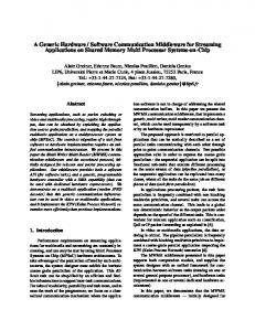
tion probability among two variables and has to exceed a minimum value for the correlation to be reported as significant. The minimal value depends on the number of participants in the experiment. When the correlation coefficient exceeded 0.506 with p < 0.05 for N = 12 the results were reported as significant and displayed in a scatter diagram. It is generally recommended that at least ten (N = 10) users participate in an experiment that is analyzed by statistical methods (Dix et al. 1993). The data sets from questions 6 and 7 in Table 2 are plotted in the scattergram of Figure 8. It represents the relationship between the difficulty of understanding program code (abbreviated to “understanding old code” and measured along the Y-axis) and the usefulness of having rationale as an aid for the understanding
A. Mørch 81
FIGURE 8. Relationship between understanding old code (Question 6) and usefulness of rationale to aid this understanding (Question 7) shows a significant positive correlation of 0.61 (p < 0.025; N = 12). The small digits next to each point is user-id number, and an enlarged point indicates that more than one respondent had that combination of answers. A high correlation produces a clear diagonal in the diagram
Understanding of old code
Not at all difficult 6 Not at all difficult 5
1
5, 8
2
9 4
4
7
11
3
3 10
2
12
Very Very 1 difficult difficult
6
0 0
1 Totally Totally useless useless
2
3
4
5
rationale UseUsefulness fulne ss o fof rat io nale
(abbreviated to “usefulness of rationale” and measured along the X-axis). This relationship shows a significant positive correlation of 0.61 (p < 0.025; N = 12). The data shows that when the code was easy to understand, the rationale was particularly useful, or alternatively, the more useful the rationale was, the more easier it was to understand the code. It also shows that when the users didn’t think that the rationale was any useful, they also thought it was difficult to understand the code, or alternatively, that when users thought the program code was difficult to understand, they also thought that the rationale was not very useful.
6
7 TVery Very useful useful
The latter reading points out a potential weakness of rationale: its complexity is proportional to the complexity of the program code, and for users to acknowledge the usefulness of rationale they also have to understand the code. This identifies an area for further work on design rationale since its complexity ought to be within the reach of end-users regardless of the complexity of the code; assuming that users have introductory level skills in programming. In other words, rationale ought to be useful for the comprehension of complex programs as well as for the comprehension of simple programs. What the threshold level of complexity should be (if at all determinable), how one should present rationale so that it
A. Mørch 82
does not reach beyond this level, and how to better measure the usefulness of rationale from this perspective need to be further investigated. The major factor contributing to the writing of new code was the access to old code for copy-paste-and-modify (Question 9 in Table 2; median 6.5/7). There was no direct correlation between the usefulness of rationale and the writing of new code, but there was an indirect relationship since I found a positive correlation of 0.61 (p < 0.025; N = 12) between the useful of rationale for the understanding of old code (Figure 8), and a slightly less positive correlation of 0.59 (p < 0.05; N = 12) between the understanding of old code and the writing of new code (Question 6 and Question 8 in Table 2). This indicates that program comprehension and program extension may be related. This also needs to be further investigated.
6. Current limitations The following four steps have to be taken for each new graphical shape application unit to be added to BasicDraw: (1) create a shape class, (2) create a menu item to instantiate the shape, (3) create a menu to instantiate the menuitem, and (4) create an extension to instantiate the menu during initialization of the program. All the four steps can be accomplished by simple extension in the same way KitchenCabinet was constructed from BasicRectangle. The last three steps, however, require much less code to be written than the first step, and it can partly be automated by the computer. The remaining tailoring can be done by customization of menu and menuitem titles.
Only the first step was tested in the experiment. What is more complicated, however, are the limitations imposed by the existing classification hierarchy. There are generally two types of limitations: overconstrained hierarchies and under-constrained hierarchies. Over-constrained hierarchies cause overly specialized (myopic) evolution to occur, whereas under-constrained hierarchies may prevent evolution altogether because there are no concrete classes to build the extensions on. If we want to add a palette or a critiquing component to BasicDraw, for example, we need to write more code than we need to write for simple extension since the extensions have to be built more or less from scratch. This type of extension is referred to as complex extension (Mørch 1995). Tailoring, as presented in this paper, is associated with concrete presentation objects accessible in the user interface. However, in some problem situations the user will not be able to associate the problem with a particular P-object. The user may not even be able to describe the problem at all, or if it can be described, it may be in abstract terms that are not related to the aspect-1 language of P-objects. In such cases, the user needs help in formulating the problem before it can be linked to concrete P-objects in the user interface. An open problem for further investigation is whether or not there should be a well-defined mapping between implementation code and design rationale and if there should be how it can be supported by computational means. In the current work, this has not been developed, but some connections between implementation code and rationale have been
A. Mørch 83
identified. There are parts of the rationale that are directly reflected in the implementation code and vice versa. Whether these connections should be made more visible needs to be further investigated. An approach to building such links for a particular code example has been successfully demonstrated by Redmiles (Redmiles 1992). To generalize from this, however, may be difficult, unless constraints are put on the rationale, such as formalizing it and making it executable. This will dismay much of the purpose of this work, which is to help end-users in capturing rationales from arbitrarily chosen domains, with the chief purpose of helping them understand the application better, not the other way around.
7. General discussion This section is formulated as a dialog, between the author and the future readers of this article. It is meant to serve as a starting point for a discussion yet to take place. It starts by me (author and first reader) making a first move by giving answers to some questions that have been in my mind during the writing of this article. •
•
Question: What makes the choice of kitchen design a realistic example to illustrate end-user tailoring, i.e., are kitchen designers likely to build specialized applications in this way?
capture. The solution can be improved as new problems are discovered. •
Follow-up question: Why not start the tailoring process from a specialized application, instead of a generic application. There are many specialized applications for home design?
•
Answer 1: Tailoring, as presented in this paper, will work equally well for specialized applications as for generic ones (assuming tailoring tools have been built into them). It may even be simpler to extend a specialized application since the number of extensions is likely to be smaller. However, it may be more difficult to customize a specialized application since it is usable by fewer users.
•
Answer 2: Traditionally, tailoring has been associated with “touching up” the look and feel of the user interface of an application. In the current work I want to demonstrate that tailoring can go deeper than the user interface (but not so deep that it becomes irrelevant for end-users). This is best illustrated when the application can evolve from one task-domain to another.
•
Question: What are the implications of moving outside the intentions of the original program (e.g., a rectangle made into a kitchen cabinet)?
•
Answer 1: From the standpoint of the user interface there is no difference between a rectangle shape and a kitchen-cabinet symbol: they have identical P-objects. A subjective difference (a “use distance”) is created by the user when he or she makes references to other objects (rectan-
Answer: The example is meant to illustrate a method: it is not a case study. The example and the method should be thought of as conjectural attempts at a solution to problems in software reuse and requirements
A. Mørch 84
gles, circles, and triangles; or cabinets, sinks, and stoves). An objective difference (a “design distance”) already exists in the underlying implementation code. •
Answer 2: Creative (non-myopic) application evolution is difficult with rigid application frameworks and class hierarchies. The end-user should therefore be encouraged to transcend existing implementation structures as long as this does not corrupt the old code. This requires programming languages that support type-safe extensions. This is possible with object-oriented languages such as BETA and JAVA. In the BETA example presented, the user was not allowed to change the old code, only to extend it.
•
Question: Why not use an end-user programming language such as AppleScript or Visual Basic instead of (or in addition to) an object-oriented programming language?
•
Answer 1: Language mechanisms such as subclassing and virtual binding are not available in most enduser programming languages. These language mechanisms are needed to support application evolution at the implementation level where new classes of functionality are constructed from old ones.
•
Answer 2: Interpreted, end-user programming languages provide an important intermediate level of tailoring, and should be integrated with compiled implementation languages. This is, to the best of my knowledge, not possible in BETA. It has therefore not been addressed in the current work.
•
Question: The term “implementation code” is confusing. There are usually two kinds of implementation code associated with an interactive system: implementation code for user interface and implementation code for functionality. How do you distinguish between the two?
•
Answer: I deliberately try to dissociate the user interface from the implementation code and other aspect-3 concepts. I want to make a distinction between the user interface of the running system, on the one hand, and all the implementation code that makes it work, on the other hand. This distinction will allow the enduser to design and customize the user interface in terms derived from the task-domain rather than in terms derived from a programming language. All the implementation code (for both user interface and functionality) is defined as reusable classes (BETA patterns). They implement the GUI widgets (menus, menuitems, windows, and graphical shapes). The functionality is invoked from eventhandlers defined as methods on the GUI classes. The functionality is also defined as methods on the classes.
•
Question: In the example shown in the paper, the same person (the author) both built and tailored the generic application. Doesn’t this violate the assumptions behind end-user tailoring?
•
Answer: Yes and No. It satisfies the requirement that further development takes place separated in time and geographical location. BasicDraw was developed by the author
A. Mørch 85
FIGURE 9. BETA extension layers and size of implementation code defining the structure
of the KitchenDesign environment. Each extension layer builds on the layer below, and at each layer there can be several alternative extensions (not shown).
System
Extension layer Domain-oriented extensions Tailorable generic application
Domain-oriented patterns (26Kb)
KitchenDesign
Concrete patterns (200Kb)
BasicDraw
Application framework Implementation base layer
Implementation code
Mostly abstract patterns
MacEnv MacApp
BETA
in Oslo during the spring of 95 and tailored by the author in Boulder during the spring of 96. It needs to be tested empirically by other endusers. This is part of future work.
8. Conclusions End-user tailoring is the process of adapting generic software applications to the specific needs of a user organization. This paper describes how to build and integrate tools to accomplish this. An elaborated example demonstrated how to tailor (evolve) a generic application (for graphics drawing) into a design environment for a radically different task-domain (kitchen design). A key concept in this work is the application unit (AU). An AU is the smallest, yet most general building block of a tailorable, object-oriented application. It has three separate aspects: (1) presentation object, (2) rationale, and (3) implementation code. The three aspects are accessed from the user interface of the artifact, and each aspect needs to be tailored when evolving the application from one
Programming language
task-domain to another. End-user tailoring varies in complexity depending on what aspect is addressed. End-user tailoring in the step size of an application unit provides a solution to problems in software reuse and requirements capture: how to locate artifacts for reuse (by using eventhandlers defined on application units), how to comprehend artifacts (by using the application and reading its rationale), and how to integrate and extend artifacts (designing new rationale and constructing new subclasses from concrete classes already defined in the generic application). The generic application BasicDraw was used as an example. It is implemented in the BETA programming language on a Macintosh computer using the MacEnv application framework (Figure 9) (Knudsen et al. 1993). BasicDraw itself consists of approximately 200 Kbytes of source code, whereas the domain-oriented extensions for building the kitchen design environment consist of 26 Kbytes of source code. An additional overhead was needed to manage resource files and to capture design rationale. The general recommendation I suggest is that if the
A. Mørch 86
combined work of writing the extension code and capturing the associated rationale is less than the total work involved in writing a domain-oriented design environment from scratch, end-user tailoring should be considered an alternative approach to building domain-oriented design environments.
Acknowledgments This paper was written during the spring of 1996 while the author was a visiting researcher at the Center for LifeLong Learning and Design at the University of Colorado, Boulder. Gerhard Fischer has inspired much of the this work. The paper was presented in a working group at the IRIS-19 conference in Løkeberg, Sweden, August 1996 and benefited from discussions with the other group members (Gro Bjerknes, Bo Dahlbom, Joan Greenbaum, Liisa von Hellens, Juhani Iivari, Steinar Kristoffersen, Tarja Kuosa, Fredrik Ljungberg, Kristen Nygaard, Adelakun Olayele). They gave useful feedback that led to this revised version. This work has been sponsored financially by a Dr. Scient stipend from the Research Council of Norway under grant no. 100618/410.
References Alley, P. and Strange, C. ResEdit Complete. Addison-Wesley, Reading, MA. 1991. Angeline, P.J. (Ed.) Evolution Revolution: An Introduction to this Special Track on Genetic and Evolutionary Programming. IEEE Expert 10, 3 (June 1995), 6-10.
Apple Computer, Inc. AppleScript Language Guide. Addison-Wesley, Reading MA, 1993. Biggerstaff, T. Design Recovery for Maintenance and Reuse. IEEE Computer 22, 7 (July 1989), 36-49. Bjerknes, G., Bratteteig, T. and Espeseth, T. Evolution of Finished Computer Systems: The Dilemma of Enhancement. Scandinavian Journal of Information Systems. 3 (1991), 25-45. Bjerknes, G., Ehn, P. and Kyng, M (eds.). Computers and Democracy: A Scandinavian Challenge. Averbury, Aldershot, 1987. Burkle, U., Gryczan, G. and Züllighoven, H. Object-Oriented System Development in a Banking Project: Methodology, Experience, and Conclusions. Human-Computer Interaction 10, 2-3 (1995) 293-336 Carroll, J.M. Scenario-based Design: Envisioning Work and Technology in Systems Development. John Wiley & Sons, New York, 1995. Chin, J.P., Diehl, V.A. and Norman, K.L. Development of an Instrument Measuring User Satisfaction of the Human-Computer Interface. Proceedings CHI’88 Human Factors in Computing Systems (Washington, 15-18 May 1988), ACM Press, 213218. DiGiano, C.J. Self-disclosing Design Tools: An Incremental Approach Toward Enduser Programming. Ph.D. thesis. Dept. of Computer Science, University of Colorado, Boulder, 1996. Dix, A., Finlay, J., Abowd, G. and Beale, R. Human-Computer Interaction. PrenticeHall, UK, 1993. Fischer, G. Cognitive View of Reuse and Redesign, IEEE Software, Special Issue on Software Reusability (July 1987), 6072. Fischer, G. Domain-oriented Design Environments. Automated Software Engineering 1 (1994), 177-203. Fischer, G., McCall, R. and Morch, A. JANUS: Integrating Hypertext with a
A. Mørch 87
Knowledge-based Design Environment. Proc. Hypertext’89 (Pittsburgh, November 5-8, 1989), ACM Press, 105-117. Fischer, G., Nakakoji, K. and Ostwald, J. Supporting the Evolution of Design Artifacts with Representations of Context and Intent. Proc. Designing Interactive Systems. (Ann Arbor, MI, August 1995), 715, Gamma, E.R., Helm, R. Johnson, R. and Vlissides, J: Design Patterns: Elements of Reusable Object-Oriented Software. Addison-Wesley, Reading, MA, 1995. Girgensohn, A. End-user Modifiability in Knowledge-based Design Environments. Ph.D. dissertation. Dept. of Computer Science, University of Colorado, Boulder, 1992. Greenbaum, J and Kyng, M. (eds.). Design at Work: Cooperative Design of Computer Systems. Lawrence Erlbaum, Hillsdale, NJ. 1991. Greene, J. and d’Oliveira, M. Methodology handbook. The Open University Press, Milton Keynes, UK, 1981. Henderson, A., and Kyng, M. There’s No Place Like Home: Continuing Design in Use. In Design at Work (Greenbaum, J & Kyng, M., eds.). Lawrence Erlbaum, Hillsdale, NJ, 1991, 219-240. Knudsen, J.L., Bak, L. and Nørgaard, C. The Mjølner BETA User Interface System. In J. Lindskov Knudsen, M. Løfgren, O. Lehrmann Madsen, and B. Magnusson (Eds.). Object-oriented Environments: The Mjølner Approach. Prentice-Hall, New York, NY, 1993, 227-233. Krasner, G.E. and Pope, S.T. A Cookbook for Using the Model-View-Controller Userinterface Paradigm in SmallTalk-80. JOOP 1, 3 (August/September, 1988), 2649. Kristensen, B.B., Madsen, O.L., Møller-Pedersen, B. and Nygaard, K. Classification of Actions, or Inheritance also for Methods. Proc. ECOOP’87 European Conf. on Object-oriented Programming (Paris, June
15-17, 1987) Lecture Notes in Computer Science 276. Springer-Verlag, 98-107. Krueger, C.W. Software Reuse. ACM Computing Surveys 24 2 (June 1992), 131183. MacLean, A., Carter, K., Lövstrand, L. and Moran, T. User-tailorable Systems: Pressing the Issues with Buttons. Proc. CHI’90 Human Factors in Computing Systems (Seattle, April 1-5, 1990), ACM Press, 175-182. Madsen, O.L., Møller-Pedersen, B. and Nygaard, K. Object-Oriented Programming in the BETA Programming Language. Addison-Wesley, Wokingham, 1993. McCall, R. Issue-serve Systems: A Descriptive Theory of Design. Design Methods and Theories. 20, 8 (1986), 443-458. Microsoft Corporation. Visual Basic User’s Guide. 1994. Moran, T. P., and Carroll, J.M. (Eds.) Design Rationale: Concepts, Techniques, and Use. Lawrence Erlbaum, Hillsdale, NJ, 1996. Mørch, A. Application Units: Basic Building Blocks of Tailorable Applications. Proc. 5th International East-West Conf. on Human-Computer Interaction, (Moscow, July 4-8, 1995). Lecture Notes in Computer Science 1015. Springer-Verlag, Berlin, 45-62. Mørch, A. Designing for Radical Tailorability: Coupling Artifact and Rationale. Knowledge-Based Systems. 7, 4 (Dec. 1994), 253-264. Mørch, A. Three Levels of End-user Tailoring: Customization, Integration, and Extension. Proc. Third Decennial Aarhus Conference. (Aarhus, August 14-18, 1995). Dept. of Computer Science, Aarhus University, Denmark, 157-166. Nardi, B. A Small Matter of Programming: Perspectives on End User Computing. MIT Press, Cambridge, MA, 1993. Nygaard, K. Profession-oriented Languages. Proc. Medical Informatics Europe 84, (Brussels, 1984), 38-44. Pew, J.A. Instant Java. SunSoft Press, 1996.
A. Mørch 88
Popper, K.R. Objective Knowledge: An Evolutionary Approach. Revised Edition. Oxford, 1979. Redmiles, D. From Programming Tasks to Solutions: Bridging the Gap Through the Explanation of Examples. Ph.D. dissertation. Dept. of Computer Science, University of Colorado, Boulder, 1992. Repenning, A. and Ambach, J. Visual AgenTalk: Anatomy of a Low Threshold, High Ceiling End-user Programming Environment. Tech. Report CU-CS-80296. Dept. of Computer Science, University of Colorado, Boulder, 1996. Schön, D. Designing as a reflective conversation with the materials of a design situation. Knowledge-Based Systems 5, 1 (March 1992), 3-13. Williams, G. HyperCard Extends the Macintosh User Interface and Makes Everybody a Programmer. BYTE (December 1987), 109-117. Winograd, T. Bringing Design to Software. Addison-Wesley, Reading, MA, 1996. Winograd, T. and Flores, F. Understanding Computers and Cognition: A New Foundation for Design. Ablex Publishing Corporation, Norwood, NJ, 1986. Vlissides, J.M. and Linton, M.A. UniDraw: A Framework for Building Domain-specific Graphical Editors. ACM Transactions on Information Systems. 8, 3 (July 1990), 237-268.
A. Mørch 89
A. Mørch 90