Possibilities for beambased optimization of collimator settings are described. Large Hadron Collider Project. Abstract. R. AÃmann, E. Holzer, J.-B. Jeanneret, ...
EUROPEAN ORGANIZATION FOR NUCLEAR RESEARCH European Laboratory for Particle Physics
Large Hadron Collider Project
LHC Project Report 758
EXPECTED PERFORMANCE AND BEAM-BASED OPTIMIZATION OF THE LHC COLLIMATION SYSTEM R. Aßmann, E. Holzer, J.-B. Jeanneret, V. Kain, S. Redaelli, G. Robert-Demolaize, J. Wenninger CERN, Geneva, Switzerland
Abstract The cleaning efficiency requirements in the LHC are beyond the requirements at other circular colliders. The achievable ideal cleaning efficiency in the LHC is presented for the improved LHC collimation system. The longitudinal distribution of proton losses is evaluated with a realistic aperture model of the LHC. The results from simplified tracking studies are compared to simulations with complete physics and error models. Possibilities for beambased optimization of collimator settings are described.
Presented at EPAC 2004, Lucerne, Switzerland, 5 to 9 July 2004 CERN, CH-1211 Geneva 23, Switzerland Geneva, July 2004
EXPECTED PERFORMANCE AND BEAM-BASED OPTIMIZATION OF THE LHC COLLIMATION SYSTEM Ralph Aßmann, Eva Barbara Holzer, Jean-Bernard Jeanneret, Verena Kain, Stefano Redaelli, Guillaume Robert-Demolaize, Jorg Wenninger, CERN, Geneva, Switzerland Abstract The cleaning efficiency requirements in the LHC are beyond the requirements at other circular colliders. The achievable ideal cleaning efficiency in the LHC is presented for the improved LHC collimation system. The longitudinal distribution of proton losses is evaluated with a realistic aperture model of the LHC. The results from simplified tracking studies are compared to simulations with complete physics and error models. Possibilities for beambased optimization of collimator settings are described.
REQUIRED CLEANING EFFICIENCY Halo particles are characterized by their normalized offsets Ax,y in the transverse coordinates x, y [1]: sµ Ax
=
x √ ²x βx
¶2
µ +
αx x + βx x0 √ ²x βx
N 1 X H(Ar − ac ) . N i=1
Ramp
450 GeV
1e+014
7 TeV 1e+013
1e+012
Ideal design 1e+011 1e-005
0.0001
0.001
0.01
Local collimation inefficiency [1/m]
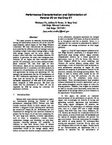
Figure 1: The maximum total intensity is shown versus local collimation inefficiency. A beam lifetime of 0.2 h at top energy and 0.1 h at injection is assumed. The design goal for local inefficiency is indicated.
BEAM TRACKING WITH COLLIMATORS
¶2 .
(1)
The same definition applies for Ay . The terms β, α, and ² are the beta and alpha Twiss functions and q the emittance. The normalized radial amplitude Ar = A2x + A2y of a particle is introduced. In order to define the cleaning inefficiency ηc a variable normalized ring aperture ac is considered. For N particles impacting at the collimators the cleaning inefficiency is defined as: ηc (ac , n1 , n2 ) =
Maximum intensity [protons]
1e+015
(2)
Here, H is the Heaviside step function, returning 1 for Ar ≥ ac and zero otherwise. The cleaning inefficiency gives the probability for a proton to escape the collimators and reach at least a normalized amplitude ac for given settings n1 and n2 of primary and secondary collimators. Losses are diluted over some length Ldil and a local cleaning inefficiency η˜c = ηc /Ldil is defined. The quench level Rq is estimated to be 7 × 10⁸ protons/m/s for 450 GeV and for slow, continuous losses [2]. For 7 TeV a value of 7.6 × 10⁶ protons/m/s is obtained. The total intensity Ntotq at the quench limit Rq and for a minimum beam lifetime τmin is given as: Ntotq = τmin · Rq /˜ ηc . It is numerically evaluated for the LHC in Figure 1. The most stringent requirements on the collimation inefficiency arise at top energy. The nominal intensity of 3 × 10¹⁴ protons per beam requires a local collimation inefficiency of 2 × 10⁻⁵ m−1 . Injection has less strict requirements.
All studies discussed in the following refer to phase 1 of LHC collimation [5]. The prediction of cleaning efficiency was performed in the past with quite simplified computer codes and detailed loss predictions along the ring were not easily possible. Chromatic and non-linear effects were not fully included in the simplified tracking. With the availability of modern computers tracking can now be done under much more realistic assumptions. The collimator scattering routines from K2 [3] and COLLTRACK were implemented into SIXTRACK [4]. The particle tracking can now be performed in SIXTRACK including full chromatic and non-linear effects, coupled motion, all available error models, beam correction, longitudinal beam dynamics, beam-beam models, etc. The trajectories are tracked through every magnetic element, allowing to save trajectories of halo particles for later analysis in the aperture model. The predictions of COLLTRACK/K2 and SIXTRACK are compared in Figure 2 for some cases. A very good agreement is seen.
DETAILED APERTURE MODEL Detailed comparisons to the quench limit require prediction of the longitudinal loss distribution. For an ensemble of 106 lost particles 103 protons will escape from the cleaning insertion if the inefficiency is 10−3 . If it is known over what length protons are lost in the cold aperture, the loss rates can be compared to the requirements from Figure 1. A detailed aperture model was set up for the LHC. Particle trajectories are saved from the tracking programs and are then compared to the LHC aperture. An example is shown
1
10
0.01
0.001
0.0001
7
8
9
10 11 ac [σ r]
12
13
14
15
1 Cleaning inefficiency
COLLTRACK/K2 SIXTRACK 0.1
Local Cleaning Inefficiency [ 1/m ]
SIXTRACK
0.1
10
10
10
10
10
IP2
-1
IR3
IP5
IR6
IR7
IP8
IP1
Quench limit
-3
-4
-5
-6
0
0.001
IR4
-2
5
0.01
10
15
20
25
Longitudinal coordinate [ km ]
7
8
9
10
11 ac [σ r]
12
13
14
10
15
Figure 2: Comparison of inefficiency from COLLTRACK/K2 and full SIXTRACK tracking. Results show betatron collimation at 7 TeV (top) and 450 GeV (bottom), ideal set-up, collimators at 6 σ/7 σ and a horizontal beam halo. The impact parameter is about 0.5 µm.
in Figure 3. Loss points can be localized with an almost arbitrary resolution. The loss distribution can be determined all around the ring. An example of losses due to tertiary halo is shown in Figure 4 for betatron cleaning at injection and top energy. Future studies will include error models, higher statistics, different operational modes and detailed interpretation of ratio between loss and quench limit, also including azimuthal loss location as illustrated in Figure 5.
Local Cleaning Inefficiency [ 1/m ]
Cleaning inefficiency
COLLTRACK/K2
10
IP2
-3
IR3 IR4
IP5
IR6 IR7
IP8
IP1
-4
Quench limit 10
10
-5
-6
0
5
10
15
20
25
30
Longitudinal coordinate [ km ]
Figure 4: Loss distribution of tertiary halo with 10 cm resolution around the ring with injection (top) and low beta (bottom) optics.
BEAM-BASED OPTIMIZATION Horizontal coordinate [m]
0.20 0.15 0.10
IR7 Betatron Cleaning
IR8 LHCb
0.05
ARC
0 -0.05 beam direction
-0.10 -0.15 -0.20 20.0
super-conducting machine area
20.5
21.0
21.5
22.0
22.5
23.0
23.5
Longitudinal coordinate s [km]
Figure 3: Example of the LHC aperture between the betatron cleaning insertion and IR8. The trajectory of a 7 TeV halo particle (escaping from a secondary collimator) is plotted. The proton touches the aperture in the IR8 triplet.
The beam-based optimization of the LHC collimation system is challenging due to the tight tolerances and the many degrees of freedom. However, it is important to realize that a natural learning experience can be followed while the intensity is being pushed upwards. Three regimes can be distinguished: One-stage cleaning: Only the three primary collimators are used. Cleaning efficiency is expected to support around 2 × 10¹² protons at 7 TeV and around 5 × 10¹³ protons at injection. This one-stage set-up is quickly implemented and very robust against any kind of errors. Secondary collimators can slowly be commissioned in parallel to other tasks. The cleaning efficiency at top energy can easily be enhanced by local cleaning at the triplets. Two-stage cleaning without skew: Two-stage cleaning is first implemented for momentum cleaning and horizontal and vertical betatron cleaning. The skew halo is not yet collimated and a somewhat increased cleaning inefficiency
BPM
Beam screen of Q6
1500
1000
500
0.02
y[m]
Number of particles hitting the beam pipe
2000
0
- 0.02
- 0.02
0 20.215
20.220
0 x[m]
20.225
0.02
20.230
positioned the beam losses will indicate the next collimator bottleneck. A similar procedure can be performed with long orbit bumps through the collimation region. Collimator bottlenecks can be identified versus phase and amplitude of the closed orbit bump. Orbit knobs: In the case of closed orbit drifts all collimators in a local region can be adjusted in a knob fashion, specifying amplitude and phase of the orbit drift. Beta beat knobs: In the case of transient changes in beta beat the collimators can be adjusted such that the beta beat modulation is compensated. Input would be amplitude and phase of beta beat, most probably adjusted empirically by trial and error.
Longitudinal coordinate [ km ]
CONCLUSION AND OUTLOOK Figure 5: Loss distribution of tertiary halo with 10 cm resolution around the first super-conducting quadrupole right of IR7 for injection (COLLTRACK data). The azimuthal distribution of proton impacts is also shown. can be envisaged, depending on the beam loss processes. Full two stage cleaning: All phase 1 collimators are used. The design performance supports about 50% of nominal intensity or 1.5 × 10¹⁴ protons at 7 TeV. The pursue of such an evolutionary strategy will allow adiabatic set up of collimators in parallel to beam commissioning. Collimator set-up can be envisaged in various ways. A traditional set-up procedure could be done like this: Initially about 5-10 nominal bunches are stored. The beam is then scraped to 3 σ in horizontal and vertical planes. The scrapers define a unique and stable beam edge. For the collimator of interest the first jaw is selected and its angle changed until the BLM’s indicate that the first edge touches the beam. Readings of BPM’s and jaw positions are recorded. The first edge is moved out and the procedure is repeated for the second edge. For the second jaw the steps listed above are repeated. Finally, the jaws are moved to the calibrated 3 σ gap, centered around the beam. The gap center, BPM readings and gap opening are recorded. The collimator is opened. The procedure is repeated for the other collimators. Once all collimators have completed this beam-based alignment, the system can be moved to target positions. Further optimization of cleaning efficiency is performed by empirical collimator adjustments based on a small number of critical BLM’s (where we are most likely to quench). In the LHC it can also be envisaged to try more advanced algorithms for collimator adjustment. Collimators checks with equal settings: All collimators are adjusted to the same normalized gap size (e.g. 6 σ). Beam intensity must respect the one stage efficiency. Now the emittance is slowly increased. Losses will first occur at the collimator that is displaced and can easily be detected with BLM’s. The center of the gap is adjusted such that losses are minimized. Once this collimator is better
The tracking engine of SIXTRACK has been extended to include proton scattering on collimators. Results from SIXTRACK and COLLTRACK/K2 show excellent agreement. Limitations in the previous collimation studies can now be overcome. Future studies will include full chromatic and non-linear effects, coupled motion, error models from MAD and SIXTRACK, beam correction, longitudinal beam dynamics, beam-beam models, advanced diffusion models, etc. The SIXTRACK engine tracks the trajectories through all magnetic elements, allowing to save trajectories of halo particles for later analysis in a detailed aperture model. Such a complete aperture model has been set up for the LHC. Longitudinal and azimuthal coordinates of loss points can be identified with great precision (10 cm over the 27 km length of the LHC). Loss patterns of halo protons have been generated, with the preliminary conclusion that efficiency goals are met. Future collimation studies will identify critical loss points. Traditional and advanced concepts for collimation set-up have been shortly presented. The ”natural” commissioning of the collimation system from one-stage cleaning to limited two-stage cleaning and finally to full two-stage cleaning has been outlined. Future simulation studies will aim at describing the set-up and optimization of LHC collimators in detail. This includes more detailed estimates on efficiency and allowable intensities, effects of imperfections, identification of critical observation points, studies of advanced and efficient procedures and other studies.
REFERENCES [1] The LHC Design Report, Vol. I, The LHC Main Ring, CERN2004-003 (2004). Chapter 18. [2] J.B. Jeanneret, D. Leroy, L. Oberli and T. Trenkler. LHC Project Report 44 (1996). [3] T.Trenkler, J.B.Jeanneret, CERN SL/Note94-105(AP), 1994. [4] F. Schmidt, ”SixTrack, User’s Reference Manual”, CERN SL/94-56 (AP). [5] R. Assmann et al. “An Improved Collimation System for the LHC”. These proceedings.