Experimental Validation of a Mass Efficiency Model for an Indium Liquid Metal Ion Source M. Tajmar*, A. Genovese Space Propulsion, ARC Seibersdorf research GmbH, A-2444 Seibersdorf, Austria
Abstract A model is derived linking microdroplet emission of a Liquid-Metal-Ion-Source (LMIS) to the actual current-voltage characteristic and operating temperature. All parameters were experimentally investigated using an Indium LMIS confirming the relationships found. The model allows for the first time to optimise LMIS for low droplet emission at high emission currents. This is very important for the application as a thruster developed at ARC Seibersdorf research. It can be also used to extrapolate droplet emission values along the current voltage characteristic.
PACS: 61.25.M
*
Research Scientist, Tel: +43-50550-3142, Fax: +43-50550-3366, Email:
[email protected]
Page: 1
1. Introduction For more than 5 years, Seibersdorf research is developing a Field-Emission-ElectricPropulsion thruster1 based on an Indium Liquid-Metal Ion Source (LMIS). For this type of application, a relatively high current (several hundred µA) needs to be extracted from such LMIS. Common to all LMIS, at currents higher than a few µA, instabilities occur and microdroplets are emitted in addition to the ion current. For the application of a LMIS as a thruster, this is an unwanted effect since propellant will be consumed at a much higher rate and the microdroplets will deposit on the extractor electrode. This deposition can close the extractor electrode being a lifetime limiting factor. In this paper, a simple relationship between droplet emission and LMIS operating conditions is presented and verified with experimental data. This is a major step along the development of LMIS into high emission current regions with maximum efficiencies as required for the application as a thruster.
2. Mass Efficiency Model
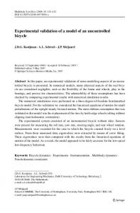
An Indium LMIS consists either of a needle covered with Indium or a capillary with Indium inside, which is heated above the Indium melting point (156.6 ºC). Then a sufficiently high potential V is applied between the emitter and an extractor electrode until a field strength of 109 V/m is reached at the tip. A so-called Taylor cone is formed as an equilibrium between the surface tension and the electric field strength with a jet protruding due to space charge (see Figure 1). Atoms are then ionised at the tip of the jet and accelerated out by the same field that created them. The expelled ions are replenished by the hydrodynamical flow of the liquid metal. The mass efficiency of a LMIS is defined as the ratio between mass emitted as singly charged ions and the total mass loss of the liquid metal reservoir m:
mIon I dt . e m
(1)
After a certain threshold current Ic, instabilities at the jet cause the emission of microdroplets which carry only little charge. This considerably increases the mass loss m and lower the overall mass efficiency . Such droplets are also called Rayleigh instabilities. If these instabilities increase, even bigger droplets are emitted from the shank of the liquid metal surface, called Faraday droplets. Therefore, if one wants to increase mass efficiency, the source of all droplets, the Rayleigh instabilities, needs to be reduced. As proposed by Vladimirov et al in the literature2,3, such Rayleigh microdroplets are created, if the time necessary to form a droplet t0 is smaller than the time necessary for the liquid to flow along the jet length h/v, t0
h . v
Page: 2
(2)
Hence, for high mass efficiency, the droplet formation time t0 needs to be maximised and the flow speed v of the liquid towards the emission site minimised. Certainly, the most dominant influence to t0 is the viscosity of the liquid metal surface, given by , T
exp
(3)
where and are constants and T is the liquid metal temperature. We therefore expect, that mass efficiency is higher close to the melting point than at higher temperatures. This is in qualitative agreement with the numerical solutions for a more detailed model as in Vladimirov et al1. The second parameter in the criterion of Equ. (2) is analytically more accessible. We can express the height of the jet h as 2
aE h r i , V
(4)
where r is the distance from the emission zone to the extractor electrode, a the radius of the jet, Ei the characteristic field for ion evaporation and V the applied potential (see Figure 1). The velocity v of the liquid metal towards the emission zone and the jet radius a can be approximated as a2
mIon 8 1 I , v Ei , eEi 8
(5)
where is the liquid metal density. Combining Equs. (4) and (5), we arrive at h 8mIon r I 2 . v e V
(6)
The distance r defines the starting voltage for achieving the characteristic field Ei. Hence, this equation relates high mass efficiency (minimum h/v) with the slope of the current-voltage characteristic by (I.V-2). A steep I-V characteristic curve (high currents at low voltages) will have a much worse mass efficiency (h/v rapidly gets larger) along higher currents than a more flat I-V characteristic (high currents at high voltages). Mass efficiency can therefore be expressed by:
rI f T , V2
where is a proportional constant.
Page: 3
(7)
3. Experiments Equ. (7) was tested for needle and capillary emitters. Figure 2 shows mass efficiency plotted against the model parameter r*I/V 2 for both type of emitters. The emitter data are given in Table 1. In all tests, the current for the electric heater around the Indium reservoir was constant. The proportional relationship can be seen very clearly. This confirms the model relationship outlined in section 2. The curve constants and f(T) seem to be different, due to the different electric field distribution from a capillary and a needle emitter as well as the different heater currents used. We also tested mass efficiency at a constant emission current and voltage (I, V) against different reservoir temperatures T investigating f(T) in Equ. (7). For the capillary, the (I, V) point was 50 A and 7100 V, for the needle emitter 200 µA and 8000 V. Figure 3 plots f(T) over the reservoir temperature. We extrapolated f(T) to the Indium melting point T=156°C and normalised f(T). The plots confirm our analysis that lower temperatures produce less droplets (the higher viscosity increases the time to form a droplet), and thus, mass efficiency will be higher. Close to the melting point, the influence is small. However, if one chooses a temperature much higher than the melting point, mass efficiency will go down very quickly. This has actually been observed in several tests. The deviation from the two curves at higher temperatures is due to the different mass efficiencies. As we will see next, a mass efficiency below 10% produces also Faraday droplets which are not included in our model which causes mass efficiency to drop more quickly than predicted. The I-V characteristic is influenced by the cross section of Indium flowing towards the emission zone. If the cross section is small, a higher voltage is required to extract the same amount of current than if the cross section would be large. For a capillary emitter, the cross section is defined by the capillary hole, needle emitters define their cross section by the film thickness of Indium along the needle. Remarkably, although Indium is liquid during emission, the initial film thickness on the needle remains constant. This was confirmed by several long term tests, especially during an 820 hours test at a current of 150 A (Genovese et al, 2001), where mass efficiency, and thus the film thickness, did not change along the test. By changing the film thickness on the needle before the test (e.g. through a new wetting procedure), different I-V characteristic curves can be obtained. The control of the film thickness is therefore a very important parameter for manufacturing high mass efficiency emitters. We tested several emitters at the same emission current, starting with an initial thick Indium film on the needle. By subsequent reduction of the film thickness, the voltage increased for the same current, and mass efficiency increased accordingly. Figure 4 shows the relationship again with our mass efficiency parameter (I/V-2), Table 2 gives the emitter data. We observe a linear relationship above 10% mass efficiency confirming again the model in section 2. Below 10%, mass efficiency drops even quicker because the model only predicts Rayleigh droplets. If those Rayleigh droplets reach some intensity, they trigger the emission of bigger Faraday droplets along the liquid metal shank which make mass efficiency much worse. Our experiments show that the transition between Rayleigh and Faraday droplet domination is reached at this 10% mass efficiency value.
Page: 4
The different steepnesses of the curves (especially between emitter C and the rest) is due to the different heater currents and therefore f(T). Emitter C had a higher f(T) which makes the curve more flat. The I-V characteristics for Emitter C at a mass efficiency of =2.5% and 34% is plotted in Figure 5. We can see clearly that a flatter curve (higher voltage for the same current) has a higher mass efficiency, as we expect from the factor I/V 2. Unfortunately, a flat I-V characteristic also means a higher power to ion current ratio, or speaking in terms of propulsion, a higher power to thrust ratio. For space applications where power and maximum voltage are typically limited, this is not a good scaling law. However, our scaling formalism allows to optimise the thruster, with a trade off study regarding the power budget, for a certain mass efficiency. We can also use the model to predict mass efficiency behaviour along the emitted current or thrust. The I-V characteristic for a LMIS can be modelled as V I Vs .
(8)
where and are constants and Vs is the starting voltage. If Vs is small, we can approximate V2 I2. Putting this into our mass efficiency model relationship in Equ. (7), we arrive at
I 12 .
(9)
This was verified for a needle emitter as shown in Figure 6. Below 20 µA, mass efficiency is 100%. There is enough Indium re-supply towards the emission zone so that ion emission is not interrupted and no droplets are formed. Above 20 µA, there is a sharp decrease following the function given in Equ. (9). We determined (1-2)=0.42. As expected, and given in Equ. (8), this decrease of mass efficiency is linked to the I-V characteristic by the parameter .
Page: 5
4. Conclusions Following the approach from Vladimirov et al, we derived a model for LMIS linking microdroplet emission or mass efficiency with the current-voltage characteristic. This behaviour as well as additional influence from the operating temperature was experimentally verified. We found that a flat current-voltage characteristic produces less droplets. This can be influenced by changing the Indium film along a needle emitter or by choosing a different inner diameter in a capillary type emitter. As a result, higher mass efficient LMIS can be produced at the cost of a higher beam power per emitted current. We also found that an operating temperature close to the melting point will increase mass efficiency. Our experiments revealed that there is a relatively sharp transition phase between Rayleigh and Faraday droplet domination at a mass efficiency of 10%. For the first time, a verified model is available to optimise mass efficiency for a LMIS. This is very important for the application of a LMIS as a thruster. The model can also be used to extrapolate mass efficiency values for different points along the currentvoltage characteristic.
Page: 6
References [1] Genovese, A., Tajmar, M., and Steiger, W., "Indium FEEP Endurance Test: Preliminary Results", International Electric Propulsion Conference, IEPC-01- 289, 2001 [2] Vladimirov, V.V., and Gorshkov, V.N., "Stability of Liquid-Metal Ion Sources", Applied Physics A, 46, 1988, pp. 131-136 [3] Vladimirov, V.V., Badan, V.E., and Gorshkov, V.N., "Microdroplet Emission and Instabilities in Liquid-Metal Ion Sources", Surface Science, 266, 1992, pp. 185190
Page: 7
Needle Emitter A Capillary Emitter B Mass Mass Current [A] Voltage [V] Current [A] Voltage [V] Efficiency [%] Efficiency [%] 20 40 60 80 100 150 300
4400 5000 5400 5800 6380 7500 10000
100 80 65 55 50 43 32
20 35 50
7300 6600 7200
100 35 16
Table 1 Emitter Parameters for Figure 2 (Heater Current Emitter A=4.5 A, B=4.2 A)
Needle Emitter C (1g Needle Emitter D (12 g Reservoir) Reservoir) Current Voltage Mass Current Voltage Mass [V] Efficiency [V] Efficiency [A] [A] [%] [%] 150 150 150 150
9500 7700 7300 6100
70 34 10 2.5
150 150 150
8500 7800 6900
50 14 6
Needle Emitter E (12 g Reservoir) Current Voltage Mass [V] Efficiency [A] [%] 150 150 150 150
7900 7200 6800 6500
Table 2 Emitter Parameters for Figure 4 (Heater Current Emitter C=8 A, D=5.2 A, E=5.5 A)
Page: 8
50 20 10 5
Figure 1 Model Parameters for LMIS Mass Efficiency
Page: 9
Needle Emitter A (r=2.01 mm) Capillary Emitter B (r=1.82 mm)
Mass Efficiency [%]
100
80
60
40
20
0 0
1
2
3
4
5
Model Parameter (r*I/V²) * 10
6
7
9
Figure 2 Mass Efficiency vs. Model Parameter (I/V2) for Needle and Capillary Emitter along Current-Voltage Characteristic at Constant Temperature
Page: 10
Indium Melting Point, Extrapolated
1.0
f(T)
0.8
f(T) Capillary Emitter f(T) Needle Emitter
0.6
0.4
0.2
0.0 150
200
250
300
Temperature [°C]
Figure 3 f(T) vs. Reservoir Temperature T for Needle and Capillary Emitter (with Mass Efficiency Values)
Page: 11
Needle Emitter C Needle Emitter D Needle Emitter E
Mass Efficiency [%]
100
80
60
40
20
0 0
5
10
15
20
25
30 2
35
Model Parameter (I/V ) * 10
40
45
50
7
Figure 4 Mass Efficiency vs. Model Parameter (I/V2)
Page: 12
500
=2.5% =34%
Current [µA]
400
300
200
100
0 0
1000
2000
3000
4000
5000
6000
7000
8000
9000 10000 11000
Voltage [V]
Figure 5 Current Voltage Characteristics for Different Film Thicknesses for Needle Emitter C
Page: 13
110
I
100
-0.42
Measurements
Mass Efficiency [%]
90 80 70 60 50 40 30 20 10 0
100
200
300
400
500
600
700
800
900
1000
Current [µA]
Figure 6 Mass Efficiency vs. Emitted Current and Comparison with Model
Page: 14