TIR Systems Ltd. 7700 Riverfront Gate Burnaby, BC Canada V5J 5M4
1 800 663 2036 T 604 294 8477 F 604 294 3733 www.tirsys.com
___________________________________________________________________________
Extended Parallel Pulse Code Modulation of LEDs By: Ian Ashdown
Copyright 2006 Society of Photo-Optical Instrumentation Engineers. This paper was published in Proceedings of SPIE, Vol. 6337, 63370W, Sixth International Conference on Solid State Lighting, and is made available as an electronic reprint with permission of SPIE. One print or electronic copy may be made for personal use only. Systematic or multiple reproduction, distribution to multiple locations via electronic or other means, duplication of any material in this paper for a fee or for commercial purposes, or modification of the content of the paper are prohibited.
Extended Parallel Pulse Code Modulation of LEDs Ian Ashdown‡ TIR Systems Limited, 7700 Riverfront Gate, Burnaby, British Columbia, Canada V5J 5M4 ABSTRACT We introduce an alternative to pulse width modulation (PWM) for LED intensity control called “Extended Parallel Pulse Code Modulation.” Whereas PWM typically requires a microcontroller with a dedicated hardware PWM controller for each channel, we can easily implement pulse code modulation (PCM) in firmware. We show that the spectral content of PWM and PCM signals is equivalent, and so there is no disadvantage from an EMI perspective for circuit or cabling design. We next introduce a PCM-based algorithm that enables a single microcontroller to drive up to one hundred LED channels in real-time with 8- to 12-bit resolution. This parallel PCM technique is suitable, for example, for LED backlighting of video displays and LED-based theatrical lighting systems. Depending on the application, we can implement the algorithm in firmware or in hardware with a field-programmable gate array. A modification of the algorithm takes advantage of the characteristics of the Ferry-Porter law for visual flicker to reduce the modulation frequency. This extended parallel PCM technique relies on the principle of temporal dithering (adapted from digital audio techniques) to reduce quantization errors in the LED intensity signals. Keywords: Pulse code modulation, visual flicker, critical fusion frequency, Ferry-Porter law, temporal dithering.
1. INTRODUCTION When light-emitting diodes were first commercialized in 1968, their luminous flux output was a meager one millicandela per device. This quickly improved however to the point where it was necessary to dynamically dim the LEDs when used in avionic displays and similar applications. This led to the first patent on pulse width modulation of LEDs, granted in 1972 to the United State Navy1. In comparison with analog control of LED intensity, PWM has several advantages. With analog control, the drive electronics require precision analog-to-digital converters and linear power amplifiers, whereas with PWM only a power electronic switch is required. Analog control further limits the dimming range to approximately 20:1, as blue InGanN LEDs tend to emit significant amounts of yellow light at low current levels, while forward voltage differences make it difficult to manufacture LED arrays with uniform per-LED dimming characteristics. By comparison, PWM enables a dimming range of at least 1000:1, which is more than sufficient for most applications2. Finally, it is difficult to control power losses with analog drivers when LEDs are dimmed, whereas this is not an issue with digital drivers. As green and yellow LEDs were introduced, there was increasing interest in multicolor displays and illumination devices3. Low-efficacy blue GaN LEDs were known by 1979, when Westinghouse Electric received a patent for generating white light of any color temperature for illumination purposes using color LEDs4. This was followed by Matsushita Electric in 1982, which presciently proposed RGB-based LED clusters for illumination purposes5. By 1994, pulse width modulation of RGB LED clusters was a well-known technique for controlling the intensity and chromaticity of both display and illumination devices6,7. The introduction of commercial high-flux red, green, and blue LEDs in 1999 made these devices both practical and economical. Today, PWM control of LED intensity is nearly ubiquitous, with applications ranging from cell phone and PDA backlighting to architectural illumination and outdoor message signs. Discrete driver components have mostly been replaced by dedicated PWM driver circuits that are available from numerous semiconductor IC manufacturers. These ‡
[email protected]; phone 1-604-473-2335; fax 1-604-294-3733; http://www.tirsys.com. Sixth International Conference on Solid State Lighting edited by Ian T. Ferguson, Nadarajah Narendran, Tsunemasa Taguchi, Ian E. Ashdown Proc. of SPIE Vol. 6337, 63370W, (2006) · 0277-786X/06/$15 · doi: 10.1117/12.679674 Proc. of SPIE Vol. 6337 63370W-1
hardware circuits are particularly useful for control of LED arrays, as most microcontrollers cannot generate more than one or two PWM control signals.
2. PULSE WIDTH MODULATION Despite their simplicity, PWM control signals are surprisingly difficult to implement in firmware with most microcontrollers. As an example, consider these design specifications for a simple RGB LED color-changing controller: • • •
3 channels 12-bit PWM resolution 1000 Hz PWM drive frequency
These are typical values for PWM resolution and frequency when driving LEDs, but they were not chosen arbitrarily. In order to design an optimal LED driver, it is important to understand the reasons behind the choice of these values. 2.1
Square Law Dimming
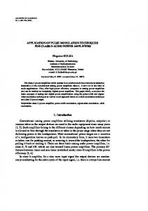
Even though the control signals typically have 8 bits resolution (for example, DMX512 theatrical control signals), it is usually necessary to apply “gamma correction” to the signal in order to compensate to the nonlinear “square law” relationship between LED intensity and perceived brightness8,9. Following Stevens’ law and lighting industry practice over the past forty or so years, this relationship is usually assumed to be: B = I 0.5
(1) 10
where B is perceived brightness and I is luminous intensity (Figure 1) . Square Law 1 0.9
Measured Luminous Intensity
0.8 0.7 0.6 0.5 0.4 0.3 0.2 0.1 0
0
0.1
0.2
0.3
0.4 0.5 0.6 Perceived Brightness
0.7
0.8
0.9
1
Figure 1 – Measured luminous intensity versus perceived brightness
Gamma correction (a term that comes from CRT television display terminology) therefore involves squaring the input signal to linearize the relationship. In theory, it requires 16 bits of output resolution to represent the smallest step of a squared 8-bit input signal. In practice, 12 bits of resolution are usually sufficient to represent a perceptually smooth dimming curve. 2.2
Flicker
Choosing a suitable PWM drive frequency involves several issues. The first issue is our ability to perceive flicker due to temporally-modulated light sources. This is predicted in part by the Ferry-Porter law:
Proc. of SPIE Vol. 6337 63370W-2
CFF = a log L + b
(2)
where CFF is the “critical fusion frequency” (measured in Hertz), L is the retinal luminance (measured in trolands§), and a and b are constants11. When the light source is pulsed at frequencies greater than the CFF, we do not perceive flicker. (As with any psychophysiological parameter, the CFF is an average of responses from a variety of test subjects – some people are inherently more sensitive to flicker than others.) What the Ferry-Porter law tells us is that our ability to perceive flicker increases as the logarithm of the increase in light source intensity. This is important if the light source is designed to be viewed directly, such as for example direct-view LEDs in outdoor signs and high-intensity LED backlighting for television monitors. The critical fusion frequency also depends on the subtended width of the light source or illuminated surface, and on the eccentricity of the light source or surface from the line of sight. For example, the CFF of a light source that has a subtended width of 20 degrees in our field of vision is approximately 50 percent greater than the CFF of a light source with a subtended width of 0.3 degrees9. Also, we are much more sensitive to flicker and movement in our peripheral vision than we are in our central vision9,12. The most important consideration however is the temporal modulation transfer function (Figure 2), where contrast sensitivity CS is defined as the inverse of Michelson contrast: L + Lmin CS = max Lmax − Lmin
(3)
and where Lmin and Lmax are the minimum and maximum luminances of the illuminated surface or light source9,13,14. 200
100
100
10
50 20
1
10
0.1
5 2 1
0.01 1 2 5 10 20 50 100 Temporal Frequency (Hz)
Figure 2a – Contrast sensitivity (2° target)
0.001 1
2 10 20 5 50 100 Temporal Frequency (Hz)
Figure 2b – Contrast amplitude (60° target)
In terms of temporal modulation for PWM light sources (which are either on or off), this becomes in accordance with the Talbot-Plateau law**: CS =
100 + DF 100 − DF
(4)
where DF is the PWM duty factor (measured in percent). It is important to interpret this information correctly. In Figure 2a, the target was a 2-degree disk presented on a large background and viewed with foveal (i.e, on-axis) vision. As such, it is applicable mostly to directly-viewed light sources. §
A troland is defined as the quantity of light incident upon the retina when the eye is looking at a surface with a luminous exitance of one candela per square meter and a pupil area of one square millimeter. ** The Talbot-Plateau law states that the perceived intensity of a light source pulsed at a rate greater than the critical fusion frequency is equal to its time-averaged mean perceived brightness.
Proc. of SPIE Vol. 6337 63370W-3
It further implies that we are insensitive to flicker for PWM drive frequencies above 60 Hz, but this is true only for foveal vision; our peripheral vision is considerably more sensitive to flicker. We can for example perceive the flickering of fluorescent lamps operated with magnetic ballasts, even though their modulation frequency is 120 Hz and a modulation ratio of about 30 percent. (This is no longer true with electronic ballasts, which operate in the region of 20 to 50 kHz and are essentially flicker-free.) Following the Ferry-Porter law, high-brightness video displays are even more prone to flickering. A minimum PWM modulation frequency of 300 Hz is often required to avoid the perception of flicker when these displays are viewed peripherally. For Figure 2b, the target was a large and evenly illuminated disk that subtended 60 degrees of the field of view. As such, it is applicable to illuminated surfaces where the light source is hidden from the field of view. The data indicates that flicker is less of a problem when there are no sharply-defined edges for the eye to detect. Regardless, it is reasonable to assume a minimum PWM frequency of 300 Hz in order to avoid perceived flicker. 2.3
Thermal Issues
An often overlooked issue is that most high-flux LED die have junction-to-case thermal time constants on the order of 5 to 10 milliseconds15. This means that if the PWM drive frequency is 100 to 200 Hz, the junction-to-case temperature difference will vary by 60% or so of the steady-state temperature 100 to 200 times a second. This problem is exacerbated by improved thermal management and consequent lower thermal resistances between the LED substrate and the surrounding environment. Of particular concern is the wire bond to the LED die. While there do not appear to have been any studies made to date of the effect of this repetitive stress on wire bond reliability, metal migration, or long-term degradation, it is likely prudent to choose a drive frequency that minimizes these thermal stresses. In particular, a minimum PWM drive frequency of 1000 Hz should sufficiently reduce the thermal stress applied to the wire bond. 2.4
Acoustic Issues
Fluorescent lamp ballasts are assigned sound ratings ranging from “A” for quiet offices and libraries to “D” for noisy industrial environments9. Modern electronic ballasts have “A” ratings, mostly because they operate above 20 kHz and so are inaudible. If an LED driver is designed to have a PWM drive frequency below 20 kHz and thus within the range of human hearing, care must be taken to design and specify the inductive components such that magnetostriction at the drive frequency does not result in unacceptably loud squealing or humming. (The driver components may be potted in thermally conductive epoxy resin to alleviate this problem, but at additional manufacturing cost.) 2.5
Microcontroller Limitations
With these parameters in mind, the design requirements for a microcontroller can be considered. While the performance of these devices has improved markedly in recent years, they are still less capable than the microprocessors used in even the least expensive desktop and laptop computers. For example, a typical inexpensive microcontroller has a clock speed of only 20 to 60 MHz, compared to 2 to 3 GHz for microprocessors. Further, many microcontrollers have at most two 10-bit PWM channels and two timers. This means that our three-channel 12-bit resolution PWM driver must be implemented in firmware. In operation, the microcontroller needs to start a timing sequence for each PWM channel and enable the channel outputs at the start of each PWM cycle. If we assume a drive frequency of 1000 Hz and 12-bit PWM resolution, this means the controller then has to compare the timer value to the three channel duty factor values 4,096,000 times a second. If any of them match, the corresponding channel outputs must be disabled. Altogether, this may require 50 or so instructions to be executed. Many inexpensive microcontrollers require four clock cycles to execute a single instruction. Assuming a 20 MHz clock, this means an instruction throughput of five million instructions per second. In other words, these microcontrollers will be too slow by a factor of fifty or so.
Proc. of SPIE Vol. 6337 63370W-4
Nevertheless, a three-channel PWM controller can be implemented in firmware by: a) reducing the PWM frequency and resolution; and b) increasing the microcontroller clock speed. Alternatively, a more expensive microcontroller with three hardware PWM channels can be selected, or a separate multi-channel PWM controller IC can be employed. (Even with on-chip PWM channels, each timer interrupt may require 50 or more instructions to process.) It is evident then that even a simple 3-channel RGB color-changing controller design pushes microcontroller technology to its limits. For a design that supports more channels, the only option may be to use separate multi-channel PWM controller ICs such as the System Logic Semiconductor SL70D0948, which features 48 nine-bit PWM channels and can be daisy-chained to provide multiple blocks of 48 channels16. The only disadvantages are that such ICs are relatively expensive, physically large (100 pins), and must be located on the same PC board as the LED power drivers if bulky twisted-pair multiconductor cables and connectors are to be avoided. If the LED power drivers are located remotely from the PWM controller IC, careful attention needs to be paid to signal shielding. Any electronic device operating at greater than 10 MHz is subject to FCC (or equivalent) regulations that limit the amount of electromagnetic interference (EMI) generated by the device. This problem typically becomes more acute as the signal clock frequency increases. The real problem with pulse width modulation is that it is in some sense a hybrid of digital and analog techniques. While it requires only digital components, the duty factor is really a quantized version of an analog signal where on-time is substituted for voltage. Even though the PWM channel may have only n bits of resolution, the microcontroller must perform 2 n operations to control the output signal. After some 35 years of use, it would seem that PWM is the only option for LED intensity control. However, it is but one of many signal modulation techniques that have been developed by the telecommunications industry over the past century.
3. PULSE CODE MODULATION Pulse code modulation (PCM) was invented in 1937 for telecommunication applications by the British scientist (and spiritualist) Alec Reeves. In an era of vacuum tube technology, it was first used for secure telephone conversations between Franklin Roosevelt and Winston Churchill through most of WWII. Today, it is universally used in one form or another for digital voice communications and music recordings. The principle behind PCM is straightforward. An analog input signal is digitized with an A/D converter with n-bit resolution. Assuming a PCM output signal with a period of t seconds, the output signal is encoded as a series of n sequential pulses, with the mth most significant bit of the digitized input signal having a pulse width of t 2 m seconds (Figures 3 and 4). The order of these pulses does not matter, as their sum of their widths will always equal that of a single equivalent PWM pulse.
( )
7.2 V
5-bit A/D Converter
10101B
PWM Converter
Figure 3A – PWM encoding example (duty factor 71.8%)
7.2 V
5-bit A/D Converter
10101B
PCM Converter
Figure 3B – PCM encoding example (duty factor 71.8%)
Proc. of SPIE Vol. 6337 63370W-5
0 1 2 3 4 5 6 7 8 9 10 11 12 13 14 15 Pulse Width Modulation
Pulse Code Modulation
Figure 4 – PWM versus PCM output signals (4-bit resolution) PCM was first proposed as an alternative means of LED intensity control by Howell17. 3.1
PCM Advantages
Unlike PWM, the pulse code modulation technique is inherently and completely digital. The duty factor of each PCM cycle is represented in binary code, which means that a microcontroller needs to perform only n operations for n bits of resolution. For a PCM channel with 12-bit resolution, this represents a reduction in computational load of over three orders of magnitude compared to an equivalent PWM channel implemented in firmware. Another advantage of PCM is that the quasi-random sequence of pulses comprising each cycle tends to minimize the thermal cycling effects of PWM modulation when the drive frequency is less than 1000 Hz. There are of course some input values that will result in a single pulse per cycle, but they should occur only infrequently. The same argument applies to acoustic issues. Whereas with PWM the periodic drive signal has a constant phase that tends to cause the LED driver magnetic components to vibrate at the drive frequency, the quasi-random PCM signal is much less likely to do so. A possible objection to PCM is that, compared with PWM, it would appear to have a higher harmonic content in its output signal and so lead to more EMI problems with long cables. However, this is not the case. Each pulse has its own harmonic content, as can be determined by Fourier analysis. Phase shifting (i.e., delaying) of these pulses does not alter their harmonic content, and so any set of PCM pulses can be phase shifted into an equivalent PWM pulse with the same duty factor.
Proc. of SPIE Vol. 6337 63370W-6
Perhaps the greatest advantage of PCM however, is that it enables a single inexpensive microcontroller to independently control of the intensity of one hundred or more LED driver channels. 3.2
Multi-channel PCM Implementation
Figure 5 illustrates the block diagram of a multi-channel PWM controller with n-bit resolution and m independent LED driver channels. Its operation can be succinctly described with the following pseudocode for the CPU firmware: DO FOREVER Read m words data FOR J = 0 to n Output J to MUX address FOR K = 1 to m Output data[K] to MUX data Toggle shift register clock ENDFOR Toggle latch Delay period / 2J ENDFOR ENDDO One advantage of this implementation is that has to perform only m ∗ n operations per PCM cycle, as opposed to m * 2 n operations per cycle for an equivalent PWM controller implemented in firmware. Moreover, the control algorithm and associated hardware are simple enough that they can be implemented in an inexpensive fieldprogrammable gate array (FPGA). It is even possible to design an FPGA circuit that does not need an internal clock18. m LED drivers
m words data
CPU Data
m-bit latch
Latch
Address
n:1 multiplexer
Data
m-bit shift register
Clock
Figure 5 – Multi-channel PCM driver block diagram Another advantage of this design is that the PCM resolution is limited only by the data bus width of the multiplexer. It is entirely straightforward to implement, subject only to the constraint of the pulse width for the least significant bit. Assuming for example a 25 kHz PCM signal with 14-bit resolution, the smallest pulse width would be 2.5 nanoseconds – a timing requirement that is unfortunately well beyond the capabilities of commercial microcontrollers. A more important advantage however is that the PCM output signals are transmitted serially from the multiplexer to the shift register and its associated latch. This means that not only can the shift register and latch be located remote from the CPU and multiplexer with a single four-wire connection, but that multiple shift register / latch pairs can be daisy-chained to control a multiplicity of LED drivers over extended distances. Further, each shift register / latch pair can be constructed using industry-standard and very inexpensive 8-bit ICs.
Proc. of SPIE Vol. 6337 63370W-7
4. EXTENDED PULSE CODE MODULATION If the PCM method has a disadvantage, it is that its resolution is constrained by the timing requirements of the shortest pulse. It would be much better if this could be limited to a reasonable value that is within the capability of commercial microcontrollers. 4.1
Signal Dithering
Compact discs store digitized audio signals with 16-bit resolution. Unfortunately, an audio signal digitized with 16 bits of resolution has noticeable distortion, particularly on quiet passages in orchestral recordings. To overcome this problem, audio engineers intentionally add random noise to the audio signal in a process called “dithering.” The listener then hears a very slight background hiss that tends to mask the distortion of the coarsely quantized signal19. A similar technique with the same philosophy was commonly used when desktop computer video cards were limited to 256 colors. Photographic and computer-generated images with smooth color gradations (such as for example a background sky) tend to show objectionable color banding. Adding random noise to each pixel value produced an image that looked somewhat grainy, but which did not have noticeable color banding. Consider then a PWM or PCM signal with 11-bit resolution and a frequency of 1000 Hz. If alternate cycles of the signal vary by one bit, then the time-averaged signal will appear to have an intensity with an apparent resolution of 12 bits. Taking this further, varying the signal by one bit over 2 n cycles will increase the apparent resolution of the signal by n bits. We have called this technique “extended pulse code modulation.” This technique works because the human visual system integrates signal above the critical fusion frequency. The varying signal results in flicker with a maximum contrast sensitivity of: CS =
1 + 2 −m
(5)
1 − 2 −m
where m is the PWM or PCM signal bit resolution. Referring to Figure 2, it can be seen that this technique will not produce noticeable flicker as long as the drive frequency is greater than 2 n * 60 Hz. 4.2
Extended PCM implementation
Extended PCM can be implemented in firmware or hardware20. As an example of a hardware implementation, the circuit shown in Figure 6 can be used to dither each of the input data values. Its operation is non-obvious, and so is described in detail as follows: 1) An 11-bit input signal D0–D10 is connected to an 11-input NAND gate. This gate outputs high for all signals except hexadecimal 0x1F (all input lines high), for which it outputs low. 2) Input lines D3–D10 are further connected to a 9-bit adder circuit. Depending on the state of the input line C0 to the adder, the 8-bit output signal B0–B7 is either equal to D3–D10 or (D3–D10) + 1. 3) Input lines D0–D3 are further connected to a 3-bit programmable counter, and represent the counter preset value when the Reset input line is toggled. 4) The Sync input line is toggled at 1000 Hertz, and represents the clock signal for the divide-by-eight counter and the 3-bit programmable counter. 5) The Init input line is toggled once to initialize the divide-by-8 counter. This counter then toggles its Out output line once for every eight Sync pulses, which in turn resets the 3-bit programmable counter via its Reset input line. 6) Together, the two counters function as a 3-bit PWM controller with a frequency of 1000 / 8 = 125 Hertz. The output of the 3-bit programmable counter is AND’d with the output of the 11-input NAND gate to generate the C0 input for the 9-bit adder.
Proc. of SPIE Vol. 6337 63370W-8
7) The purpose of the AND and NAND gates is to ensure that the input signal (D0–D10) is not incremented by the 9-bit adder when all input lines are high. This prevents the output signal (B0–B7) from “rolling over” from 0x1F to 0x00 when the 3-bit PWM controller output is high. B7 D10
9-bit adder
B0
D00
C0
Out 3-bit programmable counter Clk
Reset
Sync
Init
Clk
Out Divide-by-8 counter
Figure 6 – Extended PCM data conversion circuit The circuitry shown in Figure 6 can be easily implemented in hardware using off-the-shelf TTL integrated circuits. For commercial applications however, it is likely more economical to implement using an FPGA or custom applicationspecific integrated circuit (ASIC) with a microcontroller core to handle network communications and other housekeeping tasks.
5. CONCLUSIONS In this paper we have introduced two variants of pulse code modulation for LED intensity control. The first variant enables a single microcontroller to drive up to one hundred LED channels in real time with 8- to 12-bit resolution using inexpensive industry-standard ICs, while the second variant takes advantage of temporal dithering to improve the effective bit resolution of the PCM signal. Both techniques offer significant advantages of existing PWM control of LED intensity, and are amenable to implementation in low-cost LED intensity controllers.
Proc. of SPIE Vol. 6337 63370W-9
REFERENCES 1. 2. 3. 4. 5. 6. 7. 8. 9. 10. 11. 12. 13. 14. 15. 16. 17. 18. 19. 20.
D. G. Delay, Intensity Control for Light-Emitting Diode Display, US Patent 3,787,752, 1972. A. Žukaukas, M. S. Schur, and R. Caska, Introduction to Solid-State Lighting, Wiley-Interscience, New York, NY, 2002. S. Gage, M. Modapp, D. Evans, and H. Sorenson, Optoelectronics Applications Manual, McGraw-Hill Book Company, New York, NY, 1977. W. A. Thornton, Jr., Method and Device for Efficiently Generating White Light with Good Rendition of Illuminated Objects, US Patent 4,176,294, 1979. T. Motozono, K. Kishita, T. Kawabata, Y. Kawasaki, and S. Fujiwara, “LED Display Devices,” National Technical Report 28(1):74-82 (Japan), 1982. M. Hodapp, “LEDs as indicators, illuminators, and full-color displays,” Photonics for Consumer Electronics, SPIE TTS Vol. 1, pp. 66-75, 1994. M. W. Hodapp, “Applications for high-brightness light-emitting diodes,” in G. B. Stringfellow and M. G. Crawford, Eds., High Brightness Light Emitting Diodes: Semiconductors and Semimetals Volume 48, pp. 228-356, Academic Press, San Francisco, CA, 1997. ANSI, Entertainment Technology - USITT DMX512-A - Asynchronous Serial Digital Data Transmission Standard for Controlling Lighting Equipment and Accessories, ANSI E11.1-2004, American National Standards Institute, Washington, DC, 2004. M. Rea, Ed., The IESNA Lighting Handbook, Ninth Edition, Illuminating Engineering Society of North America, New York, NY, 2000. S. S. Stevens, “On the psychophysical law,” Psychological Review 64(3):153-181, 1957. C. W. Tyler and R. W. Hamer, “Analysis of visual modulation sensitivity. IV. Validity of the Ferry-Porter law,” J Optical Society of America A 7(4):743-58, 1990. C. W. Tyler and R. W. Hamer, “Eccentricity and the Ferry-Porter law,” J. Optical Society of America A 10(9):20842087, 1993. H. de Lange, “Research into the dynamic nature of the human fovea-cortex systems with intermittent and modulated light. II. Phase shift in brightness and delay in color perception,” J. Optical Society of America 48: 784-789, 1958. D. H. Kelley, “Visual responses to time-dependent stimuli. I. Amplitude sensitivity measurements,” J. Optical Society of America 51:422-429. G. Farkas, S. Haque, F. Wall, P. S. Martin, A. Poppe, Q. van Voorst Vader, and G. Bognar, “Electric and thermal transient effects in high power optical devices,” Proc. 20th IEEE Semi-Therm Symposium, 2004. System Logic Semiconductor, SL70D0948 48-output LED Driver / 9-bit PWM Controller, Technical Data Sheet SL70D0948, System Logic Semiconductor, Seoul, Korea, 2002. W. Howell, Application Note 011: An Overview of the Electronic Drive Technologies for Intensity Control and Colour Mixing of Low Voltage Light Sources Such As LEDs and LEPs, Artistic License Inc., Middlesex, UK, 2002. I. Ashdown, “Parallel pulse code modulation system and method,” US Patent Application 2005/0232132, 2005. B. Katz, Mastering Audio: The Art and the Science, Focal Press, San Francisco, CA, 2002. I. Ashdown, “Control apparatus and method for use with digitally controlled light sources,” PCT Patent Application WO 2006039790, 2005.
Proc. of SPIE Vol. 6337 63370W-10