system for analyzing software requirements to extract the inputs needed for the heuristic design approach. We then elaborate the functional design generation ...
Extracting High-Level Functional Design from Software Requirements Vibhu Saujanya Sharma§ , Santonu Sarkar§ , Kunal Verma‡ , Arun Panayappan§ and Alex Kass‡ § Accenture Technology Labs, Bangalore, KN, India. ‡ Accenture Technology Labs, San Jose, CA, USA. {vibhu.sharma, santonu.sarkar, k.verma, arun.panayappan, alex.kass}@accenture.com
Abstract—Practitioners spend significant amounts of time creating high-level design from requirements. Though there exist methodologies to describe and manage requirements and design artifacts, there is not yet an automated way to faithfully translate a requirement into a high-level design. While it is extremely difficult to generate design elements from freeform natural language due to its inherent ambiguity, it is possible to significantly improve the accuracy of the design from relatively structured and constrained natural language. In this paper we propose a technique to generate high-level class diagrams from a set of requirements, using a set of requirement-specific heuristics. In this approach, we leverage work we had previously done to first process a requirement statement to classify it into a requirement type, and then break it into various constituents. Depending on the requirement type and its constituents, our heuristics then discover a functional design comprising of coarse-grained modules, their relationships and responsibilities. We express the design as a UML class diagram in IBM Rational Software Architect (RSA) format. Our preliminary investigation shows that the resulting class diagram is rich, and can be used by practitioners as a basis for further design. Keywords-High-level Design; Functional Design; Requirements to Design;
I. I NTRODUCTION To build a Large-scale business application, practitioners typically follow a rigorous, process-driven methodology. In this process, the business experts define the requirements mostly as informal text documents, to describe the functionality that the software must exhibit when implemented. The requirement document is then handed off to the design team to create a high level design of the system. An important part of the high level design is the functional architecture (also known as functional design) of the system, typically expressed as functional modules and their interactions. Creation of a functional design is an extremely important activity for the developers, as well as for the business experts. A functional design serves as a solution blueprint that helps the business expert to analyze how accurately the functional requirements of the system have been translated in the design. The developers uses a functional architecture as the basis to create a low-level design and eventually the implementation code. It is therefore extremely important to create a functional architecture that is as faithful and complete a reflection of the functional requirements as possible. A functionally correct
and complete architecture will greatly minimize the risk of missing functionality or incorrect implementation of the functionality during system implementation. Many design tools today provide excellent support for generating code from design expressed in a modeling language such as UML [1]. However, when it comes to creating functional design from the requirement, these tools offer little help. As a result, the designers usually create functional design manually, and review the design for completeness and correctness in collaboration with the business experts. We have also found that the representation of the architecture generally remains informal, mostly as box and line diagrams created using general-purpose drawing packages. By analyzing the functional design process and reviewing the design artifacts in many projects, we observed several problems with this approach. First, the designers spend large amounts of time creating and reviewing the design artifacts. Second, a problem related to the first one is that the designers often compromise on the design artifact quality to meet the tight schedule. Finally, during the later stages of design, it becomes a Herculean task to translate the functional design into a detailed design in a formal model like UML, due to the informal nature of the functional design. The work that we report here is a step towards addressing these problems. Specifically, we propose an approach in this paper to create a UML-based functional design automatically from functional requirements. The approach, implemented as a tool we call the Functional Design Creation Tool (FDCT), uses a novel set of heuristic rules, and a domainspecific glossary of terms to create the design from a structured, natural language based requirement document. In this context we must mention that there have been several attempts in the past to facilitate creation of functional design from requirements [2], [3], [4], [5], [6], [7]. However, unlike some of these approaches [5], [6], [7], we impose a simple structure on the text document so that FDCT can extract a rich set of functional design entities using a set of novel heuristics that exploit the structure. Another novel aspect of FDCT is that the tool makes use of a set of user supplied domain specific glossaries to make that the resulting design more meaningful to the practitioners. The UML model generated by FDCT contains a set of high level analysis classes and their relationships. Though it requires expert intervention to translate them into implementation-level fine-
grained classes, we believe that the resulting outcome will be extremely useful for the practitioners to reason about the correctness and completeness of the functional architecture and establish traceability with the requirement. In what follows, the next section discusses what we mean by functional architecture. Section III explains our system for analyzing software requirements to extract the inputs needed for the heuristic design approach. We then elaborate the functional design generation heuristics in detail in Section IV. Next, in Section V, we describe the prototype implementation of the tool. Section VI discusses the related research work and some of our observations on this heuristic approach. Finally, Section VII concludes the paper. II. W HAT W E M EAN BY F UNCTIONAL A RCHITECTURE Notwithstanding widely varied definitions, a software architecture describes a blueprint of a software system to be implemented from different perspectives[8]. The description remains at a higher level of abstraction than implementation level objects. It establishes a correspondence between the system requirements, and helps stakeholders to comprehend and reason about the system. A software architecture description consists of multiple views, each describing a particular aspect of the system [9], [10]. The functional view, (also known as functional architecture, or functional design) is possibly the most important view, which describes how the overall functionality articulated in the requirements, is implemented by various subsystems, lower level subsystems, their interactions, and the services offered by these subsystems. The functional design can be described in various ways; use of UML [1] class diagrams is a popular mechanism to describe the functional architecture since it has emerged as the de-facto standard notation to describe software design among practitioners. Even though UML does not directly support many important architectural notions, we can still use the UML notations of class, aggregation, association, generalization, package, and package nesting to describe the functional architecture. In this paper we have focused on class, association and generalization notations to describe the functional architecture. Furthermore, we have used the class methods to represent the responsibilities (or services) associated with a class. III. E XTRACTION OF S TRUCTURED C ONTENT FROM R EQUIREMENTS D OCUMENTS The main input of the design creation tool FDCT is a structured representation of requirements, produced by a tool we have developed for analyzing a structured natural language requirements, called the Requirements Analysis Tool (RAT). The details of RAT have been described elsewhere [11], [12]. In this section we provide a brief overview of the analysis process of RAT its output to provide the sufficient context for our main discussion. Two key aspects of RAT that are most relevant to this paper are:
1. RAT restricts the requirement sentence to follow a syntax based on the recommendation of requirement engineering best practices [13]. The syntax in turn helps RAT to classify a requirement to a “requirement type” as explained in the next subsection. 2. Based on this syntax, RAT then performs a broad range of lexical and semantic analyses on a requirements document. In addition, RAT restricts the vocabulary used in the requirement document using a domain specific glossary of terms. As a consequence, RAT is able to generate a structured representation of the written requirements, consisting of the requirement type (based on its syntax) as well as the main roles defined for that requirements type (eg., the agent and the action). A. Requirement Types There are six requirement types supported by RAT which cover a broad range of requirements from application requirements, user capability requirements and business rule. Table I provides an overview of the syntaxes supported by RAT. A detailed description of the syntax may be found in [11]. In TableI we have illustrated the syntax for each requirement type using an example. The bold word in the example indicates an entity phrase, which can be an agent or a nonagent. An agent entity is the one that can perform an action. The underlined word indicates a RAT keyword and the italicized word denotes an action phrase. B. Glossary of Terms The vocabulary is restricted by requiring users to define all the entities and actions to be used in the requirements document in user-defined glossaries and then enforcing their usage in the requirements document. For this paper we discuss two types of glossaries supported by RAT namely, entity and action glossaries. The entity glossary (Table II) is used to capture all entities (agents or non-agents) in a solution such as systems, subsystems, interfaces, users, processes, records, and data fields in a requirements document. Here, systems, sub-systems and users are classified as agents, whereas reports and data objects are not. Currently, RAT supports following taxonomy of entity types - Generic Agent, System, Person and Generic Entity. The action glossary lists the valid actions for the requirements document. RAT uses a three-phase approach to analyzing requirements. In the first phase, RAT converts a requirement statement into a set of tokens with the help of the userdefined glossaries. The second phase uses state machines for analysis of the requirement statement’s syntax [11]. The third phase consists of semantic analysis with the help of domain specific ontology [12]. For this paper, we will show output of the first phase, which represents the structured
Table I R EQUIREMENT TYPES
Requirement Type Solution Requirement(SA): Describes a function that the solution must perform Enablement Requirement(E): Expresses a capability that the solution must provide to the user. Action Constraint (AC): Describes a constraint an entity must satisfy while performing an action. Attribute Constraint (ATC): Describes constraints on attributes and attribute values. Definition (D): Define entities. Policy (P): Describes policies to be adhered to.
Example(s) The Billing System shall produce invoices with rolling rates. Ex 1. The billing system shall allow the user to determine how much each client owes. Ex 2. The user shall be able to generate invoices. Ex 1. The banking system shall only delete an account, when the balance is zero. Ex 2. Only managers can approve time reports. Customer standing must always be one of the following: 1) Gold 2) Silver 3) Bronze. Total sale value is defined as total item value plus sales tax. Sales tax is computed on in-state shipments.
Table II S NAPSHOT OF E NTITY G LOSSARY
Agent Descriptor Order Proc. System Billing module Customer Management System Drop Ship Process Finance Dept User
Explanation System for processing orders Handles billing for order processing systems. Existing customer management system Process that controls the supply chain. User from finance dept
content that is used by FDCT to create the functional design. Consider the following requirement: SA1: The SAP System shall send vendor data to the order processing system. The tokenized output for this requirement would be: { Label> Agent, found in entity glossary> RAT keyword, modal phrase> Action phrase, found in action glossary> Entity, found in entity glossary> Agent, found in entity glossary>}. In addition, RAT also classifies this requirement sentence as one of the six types described in Table I. In the next section we now describe the FDCT. IV. H EURISTICS FOR E XTRACTING F UNCTIONAL A RCHITECTURE As we mentioned earlier, our focus is automatic generation of a functional design, comprising a high-level class diagram for the specified software system. This involves determining the Candidate Classes (CCs) and the methods which these CCs will contain. Based on the structured content that RAT provides, we have proposed an automated method to achieve the goal of generating a high-level class diagram of the system. In order to define the heuristics for generating CCs, it is necessary to understand the approach that the practitioners take. When we examined real requirement documents and manually generated functional modules, we find that the designers often derive a functional module’s name from
Type System System System Generic-Agent Person
Parent Order Processing System -
domain specific phrases in the requirement. The responsibilities that a functional module is supposed to perform are typically obtained from the action descriptions in the requirement document. For example, it would often be the case that the designer processes a requirement statement such as “The Billing System shall produce invoices” to create a functional module called “Billing” having a responsibility of “producing invoices”. By maintaining a resemblance of module names and responsibilities with the requirement document, the designer essentially establishes a traceability between the functional design and the requirement. Based on this observation we define a set of heuristic rules that converts various domain phrases into candidate classes. Upon manually analyzing sample requirements document statements and the corresponding tokenized output from RAT, we observed that for any statement, the Actor and the Second Agent(s) are the entities that request or perform operations. Thus these can be used as candidate classes (CC) of the system in a consolidated high-level class diagram representation of the functional design.Note that the candidate classes in such a diagram do not represent actual implementation-level classes of the system. Instead these represent coarse-grained units of functionality or modules of the system to be implemented. Thus we use the term candidate classes and modules interchangeably in this paper. We further noticed that depending on the structure of a requirement statement and equivalently, the requirement type (as classified by RAT in Table I), the elements to be added to the high-level class diagram change. The change is specifically in ascertaining (i) the relationship between the CCs, (ii) if a statement results in any method and, (iii) the
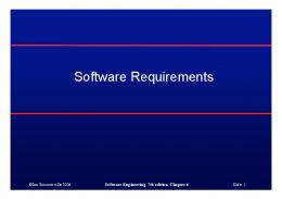
Figure 1.
owning CC of the resulting method. Thus the requirement type token which RAT provides became an important input to our approach. The other important factor which affects the way methods are added is the knowledge about the type of the candidate classes (Actor and Second Agent) in a statement. Typically, if a candidate class is known to represent a person, we would not add a method to it as we treat such classes more as an entity class, representing a real-world entity, who will typically not have any processing methods of their own. This was also incorporated in the heuristics as we will explain in detail further. We present the heuristics in detail in Figure 1. The leftmost column shows the type of requirement statement on which the heuristics names mentioned in the second column are applicable. The abbreviations SA, E, P and D have been defined and elaborated in Table I. Observe that we do not process action and attribute constraint requirement types (AC and ATC respectively in Table I) since such constraints are not meant to be included in high-level design. The third column presents the structure of the requirements statement S on which the mentioned heuristics will apply. The individual RAT tokens are shown in italics. The fourth column presents the candidate classes which will result when the heuristic is applied on the requirement. The next column shows the relationships that will result between the candidate classes after analysis. There are two
The Heuristics
kinds of relationships identified in the analysis, Association and Generalization . The last column shows the responsibilities of the identified candidate classes in terms of the method a class has to provide or support. If the requirement will result in a method or not and which CC will own the method, is decided based on the requirement type, the type of Second Agent and the Action Phrase. The ‘+’ symbol denotes a concatenation of the two strings to construct a method name.
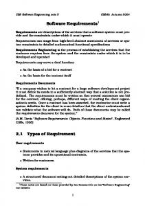
Figure 2.
Example classes, relationship and method
We now take an example requirement statement to illustrate how the heuristic approach works. Consider the requirement statement: S = “The Assign Resource Module shall choose active Projects from the Master Project Repository”. RAT classifies this as a solution action (SA) type of requirement. So we refer to the first row in Figure 1. The Actor and the Second Agent for this statement are ‘Assign Resource
Module’ and the ‘Master Project Repository’ respectively. While creating the name of the candidate class, we have considered the camel case notation of the phrases, i.e. AssignResourceModule and MasterProjectRepository. The relationship has been defined as an association between these two classes. The Action Phrase and the Entity Phrase are ‘choose’ and ‘active Projects’ respectively. We now use the RAT’s Entity Glossary (refer to Table II) to conclude that the Second Agent - Master Project Repository, is classified as a System. Thus the heuristic HSA1 applies in this case and the method found (after camel casing all strings appropriately) is: MasterProjectRepository.chooseActiveProjects(). The
reads the tokenized and tagged output from RAT containing the Actor and Agents, the Action and Entity phrases and the Requirement type. The heuristics module further reads the information of the type of the actors and agents from the Entity glossary. The plugin allows the user to specify location of the tokenized output and the glossary files before running the heuristics.
Figure 2 shows the elements that will be added to a UML model of the overall system based on this example requirement. Next we present details about an implementation of this heuristic approach.
Figure 4.
Figure 3.
Block diagram of FDCT
V. I MPLEMENTATION OVERVIEW We have implemented FDCT as a plugin to IBM Rational Software Architect, which is a popular tool that software designers and architects use for architecture definition, lowlevel design as well as implementation. The goal of the implementation was to build a proof-of-concept to understand the efficacy of the heuristics rather than a production grade tool- so the emphasis was primarily on functionality rather than anything else. The block diagram of FDCT plugin is shown in Figure 3. As shown in this figure, FDCT plugin has two main parts- (i) the heuristics module that works on the output of RAT and to find out the elements to be added to a UML model, and (ii) the UML model creator module that takes these elements and populates a UML model as a class diagram. The class diagram can be used by the designer for further refinement. The overall schematic of our method is shown in Figure 4. For the each requirement statement, the heuristics module
Overall Schematic
The heuristics module processes the inputs and applies the heuristics to the tokenized output corresponding to each requirement statement one-by-one as depicted in Figure 4. At each iteration step, the elements to be added, i.e., the candidate classes, their relationships and their responsibilities are generated by the heuristics and these act as input to the UML model creator module which actually populates the UML model. The UML model creator uses the eclipse modeling framework (EMF) [14] to create classes, methods, and their structural relationships such as inheritance, association and aggregation. For the visual rendering of these classes and their relationships through one or more class diagrams, we have used the API functions exposed by IBM Rational Software Architect (RSA) tool. Automatic generation of class diagrams without cluttering a diagram with too many classes is not a trivial task. In the current implementation we have decided to create one class diagram per package if the package has number of classes more than the user specified lower bound. We have used the layout algorithm provided by RSA while creating the diagram. We present the use of FDCT on a sample set of 23 requirement statements which were created by a subject matter expert. This set corresponds to a subset of requirements for a project resource management system. We show a snapshot of the FDCT plugin in Figure 5.
Figure 5.
FDCT as IBM RSA plugin
The FDCT plugin creates the high-level UML model in the .emx format as an RSA modeling project. The UML class diagram generated by the tool is shown in Figure 6. The figure shows the different coarse-grained modules (represented as candidate classes) of the system and the relationships (associations and generalizations) between them. The class diagram also shows their responsibilities as methods in the respective candidate classes. VI. R ELATED W ORK AND O BSERVATIONS There has been a rich body of literature covering the various natural language processing techniques to create design models, analysis of use case descriptions and other related topics. An earlier work in this direction is the use case map (UCM) [15]- a methodology to describe semi-formally, how a functional component takes part in exhibiting the intended behavior of the system. While this approach is in the domain of transitioning from a functional requirement to a functional design, the approach neither provides any guideline to automatically identify functional components, nor does it help to discover association of these components with the use case behavior. There have been attempts to relate requirements to the architecture using problem frames [2] where a problem frame is a formal representation of a problem statement as a collection of smaller subproblem. Here the underlying assumption is that the users should translate an informal requirement description into a problem frame representation. It remains to be seen how this approach can help in identifying important functional modules and their interactions in a real life scenario. The CBSP based approach [3] suggests an approach to reconcile mismatches between a requirement and architecture. While the approach helps in modeling complex relationships between various requirements and architecture, it does not directly provide any mechanism to derive the architecture from the requirement.
The relationship between requirement and architecture has also been explored in [4] where the relationship between a requirement and the architectural entity can be defined using an intermediate description. However, question remains how effectively does one create this intermediate description, specifically when the requirement is large in size. Natural language processing techniques have been exploited by several researchers to create design artifacts out of requirement documents and use case specifications. The work by Liu et al. (UCDA tool) [5] and the LIDA tool [6] are attempts towards this direction. Unlike our approach, the UCDA tool in [5] uses generic noun-phrase analysis on a rigorous programming language like use case documents to create class diagram. The tool LIDA [6], uses sophisticated natural language processing (NLP) techniques to identify important noun and verb phrases. However, the approach relies on standard noun-phrase analysis and uses the heuristic rules that utilize a generic linguistic structure. Another NLP based approach by Ilieva et al.[7] has proposed creation of object oriented analysis model from unconstrained natural language based requirement. The popular analysis and design tools namely IBM RSA (http://www01.ibm.com/software/awdtools/architect/swarchitect/) and Microsoft team system (http://msdn.microsoft.com/enus/teamsystem/default.aspx) provide visual modeling editors to create a design model or reverse engineer the model from the code. However, these tools offer little support towards transforming a requirement or a use case document into a design. FDCT’s approach of automated creation of design artifacts from requirement specification differs from the existing approaches on several accounts. First, unlike previous approaches, FDCT operates on a requirement specification, not use cases. Previous approaches such as from Liu et al. [5], LIDA [6] and Ilieva et al. [7], perform noun-phrase analysis on unconstrained natural languages to obtain the design entities. However, an unconstrained natural language is ambiguous and it becomes extremely difficult derive the underlying intent by any tool. To reduce the ambiguity, and yet to maintain the flexibility of a natural language, FDCT makes use of typed and structured requirement specifications of RAT. Use of such predefined requirement types helps us in defining more precise heuristics for FDCT. For instance, the Definition and Policy type requirements can help us in creating richer domain entity relationships. The Solution Action and Enablement type requirements helps us identifying the responsibilities associated with an agent more precisely. Second, our approach also differs from the approaches such as [2], [3], [4], [5], [6], [7] due to the fact that we make use of user supplied domain glossaries. Glossary provides an application context to FDCT. Using glossaries, FDCT can eliminate unimportant entities and introduce new domain entities, their responsibilities and their relationships
Figure 6.
Automatically generated high-level class diagram
in the design that are otherwise latent in the requirement. Third, unlike some of the other tools like UCDA [5] and LIDA [6], we chose to create EMF compliant UML models to maximize the usage of FCDT to the practitioners. An EMF compliant UML modeling is becoming a de-facto standard with high degree of interoperability to other formats. Furthermore, it is possible to perform various types of design analysis including the one in IBM RSA on the EMF compliant model. Since FDCT is actually an IBMRSA plugin, we believe that its usage, and evangelization in a real system development will be a lot more easier than any proprietary solution. VII. C ONCLUSION In this paper we proposed a method and a prototype tool for automatically creating high-level software design from the requirements using a set of heuristic rules. Our approach uses the tokenized output of requirement from RAT and various domain specific glossaries to generate a high-level UML class diagram. The resulting UML diagram consists the coarse-grained modules of the system along with their responsibilities and the relationships between them. This diagram acts as a basis for software designers to arrive at the final design of the system. The approach is thus meant to aid the software designer in an otherwise highly effort intensive process. We also presented the details of a prototype as an IBM RSA plugin, which implements our approach. The resultant UML model from a requirement specification can be opened and modified using RSA modeling editor. Note that while FDCT leverages the intermediate tokenized output and glossaries associated with our previous work RAT [11], [12], it’s novelty lies in the way it utilizes these inputs through the set of heuristics to discover and generate a rich high-level functional design out of them. Moreover FDCT
has a distinct implementation and only uses RAT as an upstream requirement pre-processing tool. As our approach is based on using a processed set of requirements, utilizing domain knowledge, domain-specific glossaries, as well as the constraints on the requirement specification, it results in an inherently richer design than a design created without any domain specific information. This in particular, lends our approach easily to automation, while other approaches either need significant human input or are dependent on rigorous specification of use cases to arrive at a high-level design. Our approach however has a few limitations. The highlevel design produced by this approach can sometimes be too coarse-grained or too fine-grained depending on the granularity of requirement statements. Note that the approach depends on the granularity of the entities contained in the entity glossary of the system and is thus limited by that when creating candidate classes. This may for example, cause a huge number of output candidate classes added in the high-level diagram. Further, we acknowledge that the set of heuristics that we have arrived at till now is by no means exhaustive or complete. In fact we are working on adding a whole new set of heuristic rules for further enhancing the output. Among others, these include heuristics for grouping high-level functional classes into different types and also to find attributes of the different candidate classes. We are currently also extending the tool to act as an IDE for design and analysis. The aim is to allow the designer have an integrated view into requirements as well as the corresponding design and allow the designer to automatically create a high-level design and then to refine it further based on the entities in the requirements that either need to be merged into higher abstractions or to be divided further. We have applied the tool on a subset of requirements
from a few business application development projects in our organization and the results were promising. The tool was able to correctly identify the key candidate classes and their responsibilities and relationships thereof. We intend to perform a more comprehensive evaluation of the tool on many more projects. This will also help us in improving the heuristics by using the findings to make them richer and more comprehensive. R EFERENCES [1] G. Booch, I. Jacobson, and J. Rambaugh, The Unified Modeling Language User Guide. Addison Wesley. [2] J. G. Hall, M. Jackson, R. C. Laney, B. Nuseibeh, and L. Rapanotti, “Relating software requirements and architectures using problem frames,” in Proc.of the IEEE Joint International Conference on Requirements Engineering, 2002, pp. 137–144. [3] P. Grnbacher, A. Egyed, and N. Medvidovic, “Reconciling software requirements and architectures: The cbsp approach,” in Fifth IEEE International Symposium on Requirements Engineering, 2001, pp. 202–211. [4] M. Brandozzi and D. Perry, “Transforming goal oriented requirement specifications into architectural prescriptions,” in Proceedings of First International Workshop From Software Requirements to Architectures (STRAW01), 2001, pp. 54–61. [5] D. Liu, K. Subramaniam, A. Eberlein, and B. H. Far, “Natural language requirements analysis and class model generation using UCDA,” in Lecture Notes in Computer Science. Springer-Verlag, 2004, pp. 295–304. [6] S. P. Overmyer, B. Lavoie, and O. Rambow, “Conceptual modeling through linguistic analysis using LIDA,” in Proceedings of the 23rd International Conference on Software Engineering, 2001, pp. 401–410. [7] M. Ilieva and O. Ormandjieva, “Automatic transition of natural language software requirements specification into formal presentation,” in Lecture Notes in Computer Science. Springer-Verlag, 2005, pp. 392–397. [8] P. Clements, F. Bachman, L. Bass, D. Garlan, J. Ivers, R. Little, R. Nord, and J. Stafford, Documenting Software Architecture. Addison Wesley, September 2002. [9] “IEEE Recommended Practice for Architectural Description of Software-Intensive Systems,” 2000. [10] P. Kruchten, “Architectural BlueprintsThe “4+1” View Model of Software Architecture,” IEEE Software, vol. 12, no. 6, pp. 42–50, 1995. [11] K. Verma and A. Kass, “Requirements analysis tool: A tool for automatically analyzing software requirements documents,” in ISWC ’08: Proc of the 7th International Conf. on The Semantic Web, 2008, pp. 751–763. [12] P. Jain, K. Verma, A. Kass, and R. G. Vasquez, “Automated review of natural language requirements documents: generating useful warnings with user-extensible glossaries driving a simple state machine,” in ISEC ’09: Proc. 2nd Annual Conf. on India Software Engineering Conference. ACM, 2009, pp. 37–46.
[13] “IEEE Recommended Practice for Software Requirements Specifications,” 1998. [14] F. Budinsky, S. A. Brodsky, and E. Merks, Eclipse Modeling Framework. Pearson Education, 2003. [15] R. J. A. Buhr, “Use case maps as architectural entities for complex systems,” IEEE Transactions on Software Engineering, vol. 24, no. 12, pp. 1131–1155, 1998.