Computers and Electronics in Agriculture 44 (2004) 203–222
Extracting the three-dimensional shape of live pigs using stereo photogrammetry Jiahua Wu a,∗ , Robin Tillett a , Nigel McFarlane a , Xiangyang Ju b , J. Paul Siebert b , Paddy Schofield a b
a Silsoe Research Institute, Wrest Park, Silsoe, Beds MK45 4HS, UK Department of Computer Science, University of Glasgow, University Avenue, Glasgow G12 8QQ, UK
Received 27 June 2003; accepted 5 May 2004
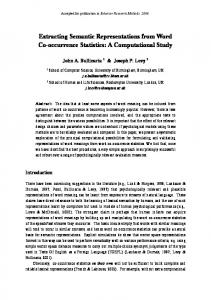
Abstract A stereo imaging system with six high-resolution cameras (3032 × 2028 pixels) and three flash units was developed to capture the 3D shapes of live pigs. The cameras were arranged in three stereo pods, which captured the side, top and rear views of each pig. The image resolution was 0.4 mm per pixel on the surface of the pig. The system was used to capture images of 32 pigs over 14 weeks as they grew from approximately 30–80 kg. They were divided into two groups on different diets, in order to induce shape differences. Each stereo view was processed to produce a range image of the surface, and for each pig the three views were integrated to produce a complete 3D mesh. The pigs were introduced singly into a standard 3 m × 4 m pen, which was large enough to provide an unobstructed view of the pigs. Each pig was initially manoeuvred by hand into a pig-sized area in one corner where the image capture took place. The majority of pigs learned to do this with little or no human intervention. The 3D imaging system reconstructed a flat test object with an rms deviation from flatness of ±0.1 mm, and an residual curvature of no more than −3.5 × 10⁻⁵ mm−1 . Depth discontinuities of 1.2 and 2.3 mm were reconstructed with an accuracy of ±0.1 mm, and a measured 451.5 mm distance parallel to the image plane was reconstructed with an accuracy of ±0.6 mm. The stereo imaging system worked successfully on the pigs by triangulating on the natural skin texture, and did not require any additional, artificial, texture to be projected. The 3D models of the pigs were qualitatively good in appearance, and locally smooth, with an rms deviation of ±0.6 mm. © 2004 Elsevier B.V. All rights reserved. Keywords: 3D; Computer vision; Shape; Pigs; Stereo; Photogrammetry
∗
Corresponding author. Tel.: +44 1525 860000x2430; fax: +44 1525 861735. E-mail address:
[email protected] (J. Wu).
0168-1699/$ – see front matter © 2004 Elsevier B.V. All rights reserved. doi:10.1016/j.compag.2004.05.003
204
J. Wu et al. / Computers and Electronics in Agriculture 44 (2004) 203–222
1. Introduction The shape, or conformation, of a live pig is an important indicator of its health and value, whether for breeding or for carcass quality. Currently most assessments of live animal conformation are carried out by eye or hand, and depend on the subjective opinion of the buyer or stockman. Conformation is an important factor in the value of a carcass, because it indicates the shape and yield of different cuts of meat (Horgan et al., 1995). The lean content of the carcass, an important quality factor, has been shown to be 80% predictable if the usual weight and ultrasound back-fat measurements are supplemented with exterior measurements, particularly the ear-to-tail length and the width of the ham (Geers et al., 1991). If the carcass quality could be reliably predicted from measurements made on the living animal, it would enable the best animals to be selected for breeding, multiplying their value several-fold through their progeny (Van der Stuyft et al., 1991a). Conformation can also be an indicator of factors such as useful lifetime, fertility and leg weakness (Van der Stuyft et al., 1991b). Leg weakness, a major cause of premature culling of breeding sows, can be apparent in the shape and stance of the legs, but visual assessments vary widely between inspectors, particularly if they lack training (Van Steenbergen, 1989). Shape plays a part in measuring the general health of the animal. In pigs, this is typically estimated from fatness, which is expressed as a condition score on a scale from 1 to 5. The main method for determining the score is by touch (Fearon, 2002), combined with a visual inspection of the shape as seen from the rear (Coffey et al., 1999; DEFRA, 2002). Weight can be estimated from shape measurements. Regular weighing is important because it allows the diet to be matched to the requirements of the pigs (Slader and Gregory, 1988; Whittemore and Schofield, 2000). A poorly constituted diet results in inefficient use of nutrients and contributes to air and water pollution (Lee and Kay, 1997). The traditional method of weighing without scales is to measure the girth just behind the front legs with a weight tape (Pope and Moore, 2002), but Schofield (1990) showed that it can also be estimated non-invasively from images. In the case of weighing, the operation is so labour intensive, and stressful for the pigs, that on many farms weight is only estimated by eye, despite the importance of regular weighing in monitoring health and regulating costly food intake (Schofield, 1990). Much research effort has been focused on the use of image analysis for automatic pig weighing, combining one or more 2D views to obtain the required measurements (Marchant and Schofield, 1993; Brandl and Jorgensen, 1996; Schofield et al., 1999). Many shape features are subtle and cannot be extracted from 2D images. With 3D data, it would be possible to extract cross-sectional areas and volumes, and to measure features such as the squareness of the back muscles, which are known indicators of lean muscle mass (Whittemore, 1998). With objective measurements of 3D shape, it would become possible to quantify the effects of growth, diet, genetics, health and posture on conformation. Work has been done on building 3D models for robotic sheep shearing (Trevelyan, 1992) and on using animal shape for carcass assessment (Stanford et al., 1998; Horgan et al., 1995). These models can provide measurements of fat thickness and estimations of muscle area and hence volume. However they rely on the carcass (or the immobilised sheep) being presented in more carefully controlled conditions than would be possible with live animals.
J. Wu et al. / Computers and Electronics in Agriculture 44 (2004) 203–222
205
Van der Stuyft et al. (1990, 1991a,b) used a structured light technique (Vuylsteke and Oosterlinck, 1990) to determine the 3D shape of the sides of pigs, initially using a model and later live pigs. This was partly motivated by the desire to measure the surface area, for the purposes of modelling the thermal interaction of the pigs with their environment. The work was successful in extracting the 3D shape of a small number of pigs, albeit at coarse resolution, and from one view only. There are many techniques for 3D measurement. Some are based on laser range finding, in which a laser spot or stripe is scanned across the surface. Commercial scanners are available, but these tend to be too slow for the purposes of scanning a moving animal. Some methods are based on structured light, the simplest form of which is the projection of light stripes onto the surface, enabling the 3D position of the surface to be calculated from its intersection with the stripes (Yang, 1993). The most advanced forms of structured light use coded patterns so that each point in the pattern can be identified without ambiguity. Structured light is well-suited to rapid capture of moving objects, although near-simultaneous capture from several viewpoints would add to the technical difficulty. In photogrammetry stereo (Faugeras, 2001), two cameras view the surface from slightly different angles. Corresponding features are matched between the two images, and the 3D surface is then constructed by triangulation. An advantage of photogrammetry over structured light is that the natural appearance of the surface is captured as a normal part of the process. A disadvantage is that it relies on there being enough features in the surface texture (visual appearance) for matching to take place. Ayoub et al. (1998a,b) reviewed various technologies for 3D imaging in medical applications, including a photogrammetry system known as C3D (Siebert and Urquhart, 1990, 1994). A novel feature of C3D was the projection of a random texture pattern onto the surface, enabling stereo matching to take place, even on featureless surfaces such as skin. To obtain a record of the natural appearance, images with and without the projected pattern were captured in rapid succession. In addition, the system contained algorithms for integrating a number of views into a single 3D mesh. A full description of the system has been given by Siebert and Marshall (2000). The aim of the work reported here was to construct a 3D imaging system, based on C3D, as a research tool for capturing the shape of live pigs, and to use this system to produce a database of pigs showing shape variations in age, weight, diet and posture. Sections 2.1–2.6 describe the imaging system. Sections 2.7–2.10 describe a 14-week trial in which 32 pigs were imaged as they grew from 30 kg to slaughter weight. Two different diets were used in order to induce differences in fatness.
2. Materials and methods 2.1. Imaging system The 3D imaging system is shown as a schematic in Fig. 1. It consisted of three stereo imaging pods, each comprising two digital cameras and a studio flash. The pods were set up so as to capture stereo images from the side, top and rear of the pig. The simultaneous operation of the camera shutters and flash units was controlled by a 2 GHz Pentium 4 PC.
206
J. Wu et al. / Computers and Electronics in Agriculture 44 (2004) 203–222
Fig. 1. Schematic of imaging system configuration.
The software which was used to construct the 3D surface from the six 2D images was the system known as C3D (see Section 1). However, unlike most previous work using C3D, the image capture system did not feature an artificially-projected texture pattern, but instead relied upon the natural surface detail of the pig skin for stereo triangulation.
J. Wu et al. / Computers and Electronics in Agriculture 44 (2004) 203–222
207
Fig. 2. Imaging equipment in operation, showing positions of stereo cameras, flashes and computer, with pig in image capture position.
2.2. Geometry of imaging pen A standard pig pen was modified for the image capture of individual pigs. This is shown in Fig. 2. The mounting positions for both cameras and flash units were such that the pigs could enter the pen without interfering with any equipment. The working floor area was approximately 3 m × 4 m, which was large enough to obtain an unobstructed view from all three directions. The actual image capture area was a relatively small (pig-sized) corner of the pen, which can be seen, marked by black tape and occupied by a pig, in Fig. 2. The method for persuading the pig to stand in one corner of such a large pen is described later in Section 2.8. The geometry of the cameras was as follows: (a) The side and rear cameras were fitted with 50 mm lenses (equivalent to 65 mm in a standard 35 mm camera), and the top camera was fitted with a 35 mm lens (equivalent to 45 mm). (b) The nominal distances of the side, top and rear cameras from the surface of the pig were 2.45, 1.70 and 1.65 m, respectively.
208
J. Wu et al. / Computers and Electronics in Agriculture 44 (2004) 203–222
(c) The lengths of the baselines for the side, top and rear stereo cameras were 600, 405 and 415 mm, respectively. (d) The angle of each stereo camera to the viewing axis (vergence angle) was about 7◦ in each pod. (e) The side and rear stereo cameras were tilted at about 15◦ to the horizontal in order to see over the wall of the pen. The lengths of the stereo baselines were chosen to be as long as possible, in order to achieve a good depth resolution, without being so long that the stereo matching (see Section 2.5) would struggle to find correspondences. The vergence angle of 7◦ was a function of the baseline, and simply ensured that the cameras were pointed at approximately the same point at the distance of the pig surface. 2.3. Specification of cameras and flash units The cameras were Kodak Professional DCS760 single-lens-reflex (SLR) digital cameras. The resolution of the CCD was 3032 × 2028 pixels, with 12-bit colour depth. This corresponded to a resolution of approximately 0.4 mm per pixel on the surface of the pig. The reason of using such high resolution, was the need to resolve sufficiently small texture details on the pig surface for integration of stereo correspondences. Each camera contained a 512 MB Compact Flash type II memory card, which could store up to 54 uncompressed images. The images were transferred from the memory card to the PC via Firewire (IEEE1394) cable, a standard which provided a fast connection. In this application, involving moving animals at high resolution, the image acquisition had to be fast enough to remove any motion blur. This could not be achieved with a fast shutter speed because unpredictable communication delays between the computer and the cameras made it impossible to synchronise all six shutters with sufficient accuracy. However, with a small lens aperture and low ambient light levels, the shutters could be left open for a considerable time without recording any significant signal, so it was possible to use a very slow shutter speed (1/8 s) combined with a fast flash (1/1500 s) to synchronise the image capture. With an image resolution of 0.4 mm per pixel, this speed was fast enough to freeze the motion of the anything moving slower than 0.6 m s−1 , which was a fast walking pace for the pigs. Each stereo pod contained a professional studio flash unit (Bowens Esprit Pro BW2066, 1000 W). All the flash units produced a consistent colour temperature of 5600 K, which did not vary with the power setting. Each flash unit was mounted with a Bowens wafer light bank system, or soft box, with dimensions 750 mm × 500 mm, in order to provide diffuse light on the surface of the pig. Each flash unit was also equipped with an optical sensor that enabled it to be triggered with negligible delay by another flash unit. The top and side units were operated as slaves to the master flash at the rear, which was controlled by the rear camera. The charge time for each flash unit on full power was about 2 or 3 s, so the time delay between two image captures could not be faster than this limit. The whole capture control strategy is shown in Fig. 3.
J. Wu et al. / Computers and Electronics in Agriculture 44 (2004) 203–222
209
Fig. 3. Capture control between the PC and three pairs of stereo camers and three flash units.
2.4. Camera calibration In order to determine the detailed geometric configuration of all six stereo cameras, in terms of their internal parameters (focal length, image centre and lens distortion) and external parameters (orientation and position), a calibration process was necessary. This was based on the direct linear transform (DLT) (Abdel-Aziz and Karara, 1971) and bundle adjustment (Karara, 1989). The calibration target used in this work is shown in Fig. 4. The pattern on the target was designed to be compatible with the C3D software used in this work (Siebert and Urquhart,
Fig. 4. Calibration target.
210
J. Wu et al. / Computers and Electronics in Agriculture 44 (2004) 203–222
1994; Siebert and Marshall, 2000). The target was a flat aluminium plate, measuring 406 mm × 406 mm. The pattern consisted of twelve black target circles, each of diameter 48 mm, on a white background. Two additional rings and a bar code provided information about the scale and orientation of the target, as well as identifying the particular target to the software. The calibration target needed to be flat and smooth, with a sharp edge between the different colours and no indentations for the black parts. The target was constructed by attaching a piece of 6 mm thick white plastic onto a sheet of 10 mm thick aluminium for rigidity. The areas which were to be black were machined out using a three-axis CNC milling machine, with an accuracy of 0.01 mm. Black shapes were then machined to fit the holes and were glued into place to produce a smooth surface. In each image of the target, the centres of the twelve black circles were automatically located. The circle coordinates were used to fit a geometric model the corresponding camera and its relative orientation to the calibration target (Abdel-Aziz and Karara, 1971; Karara, 1989). The calibration accuracy was evaluated by projecting the 3D calibration targets back into stereo images using the fitted calibration parameters. The overall calibration accuracy was found to be ±0.3 pixels in terms of the r.m.s. difference between the centres of the projected and original circles. Given that the resolution of the imaging system was 0.4 mm per pixel (see Section 2.3), this was equivalent to ±0.1 mm in world coordinates. 2.5. Stereo image matching Once the configuration of the cameras had been calibrated, the surface of the pig could be recovered in 3D world space by stereo triangulation. The geometry of stereo triangulation is shown in simple form in Fig. 5. In general, the geometry is complicated by differing focal lengths and lens distortion, which are not shown.
Fig. 5. Recovery of 3D surface via stereo triangulation. x1 , y1 , coordinates in left image; x2 , y2 , coordinates in right image; d, length of stereo baseline; f, focal length of camera; r1 , r2 , distances from point on surface to cameras; z, surface depth, normal to focal plane.
J. Wu et al. / Computers and Electronics in Agriculture 44 (2004) 203–222
211
Fig. 6. The complete stereo matching process on a single pod.
The depth z of a point on the surface can be calculated from its coordinates (x1 , y1 ) and (x2 , y2 ) in the left and right images, given the length d of the baseline and the focal length f. It can be shown that z is given by z=
df x2 − x 1
(1)
where the denominator x2 − x1 is known as the stereo disparity. The most difficult problem in any stereo analysis is to establish which pixels in the left and right images correspond to the same point in 3D space. The approach used by C3D to establish the correspondences employed a correlation-based, multi-resolution, stereo matching algorithm (Siebert and Urquhart, 1994). The correspondences were used to construct maps of the stereo disparities, from which the surface of the object was calculated by triangulation. Fig. 6 outlines the complete matching processing on a single pod. The outputs were a range image, in which the value of each pixel was the distance rl from the surface to the lens centre of the left camera, and a confidence map, which represented the probability for each pixel that the match was correct. A range image and an associated confidence map were produced in this way for each of the stereo pods. 2.6. 3D model representation by integration of multiple range images The range data described in Section 2.5 were shape descriptions of pig surfaces in their own right, and could be used directly to extract shape features. However, each range image in isolation described only a limited view of the pig, making it difficult to analyse features such as the ham that overlapped between different views. Therefore, it was necessary to fit the three range images together to form a single surface, which in this work was in the form of a 3D mesh model. The integration of a complete 3D model from the range images consisted of the following steps: (1) multi-view data registration; (2) 3D model building; and (3) model optimisation.
212
J. Wu et al. / Computers and Electronics in Agriculture 44 (2004) 203–222
(1) The registration of range images into a common coordinate frame from an initial estimate of the pose has been addressed by Chen and Medioni (1992) and Turk and Levoy (1994). Each range map was converted into a polygonal surface mesh to yield a partial-view model of the object, and the meshes were then transformed into world coordinates. In this work, the world coordinate system was defined by the first image of the target in the calibration session (see Section 2.9). This formed a good approximation to the final model, but with untidy and conflicting overlaps between the component meshes. (2) The aim of the model building process was to reconstruct an integrated representation which was consistent with the multi-view range data (Kawai et al., 1992; Rutishauser et al., 1994; Hilton et al., 1996). Integration was achieved by the volumetric approach employing implicit surfaces (Curless and Levoy, 1996; Pulli et al., 1997). (3) Finally, the model optimisation stage fitted the model to the data to a prescribed level of accuracy and produced an efficient mesh representation. The result was a 3D description of the surface. The formation of an integrated 3D model from the range images is shown in Fig. 7. 2.7. Imaging trial with pigs In the pig trial 32 pigs were divided into two groups of 16. The groups were fed ad-lib, one on a high lysine diet, and the other on a low lysine diet, in order to induce shape
Fig. 7. Recovery of a 3D model from the integration of three range images (side, top and rear views).
J. Wu et al. / Computers and Electronics in Agriculture 44 (2004) 203–222
213
differences due to differing growth rate and fat-to-lean ratio. The pig breed used was a standard commercial cross of Large White, Landrace and 25% Duroc. The trial lasted for 14 weeks, during which the pigs grew from an average weight of 30–80 kg. The pigs were weighed and images were captured at weekly intervals. Each pig was imaged at least twice during its weekly imaging session. At the end of the trial, ultrasound back-fat measurements were taken; the pigs and their carcasses were graded by experts, and five pigs from each group were dissected after slaughter to determine the ratios of lean, fat and bone. The complete data set contained two images per pig per week, spanning shape changes due to growth, diet group and individual variation. In addition, there were some sessions in which large numbers of images were captured, with the same pig in different positions, in order to collect data on shape changes due to posture. The images were stored in a 120GB database. 2.8. Image capture of live pigs The procedure for image capture of the live pigs is shown in Fig. 8. At the start of each imaging session, one pig was admitted into the imaging pen, as shown in Fig. 8a. The pen was relatively large compared to the area covered by the cameras, and the pig had to be persuaded to stand in the place where it could be imaged. Fig. 8b shows one of the authors attempting to move the pig into position, and in Fig. 8c shows an ideal final position, with the pig’s head in the corner, its flank parallel to the wall, and its handler outside the camera shot. The aim was to capture at least two such images in each session. It was not obvious before the start of the project how readily the pigs would stand in the corner, and the 14 weeks were a learning process for both pigs and humans. The main
Fig. 8. Guiding the pig into the imaging area: (a) pig entering the pen; (b) pig facing the wrong way and being guided by the handler; (c) pig standing in the ideal position.
214
J. Wu et al. / Computers and Electronics in Agriculture 44 (2004) 203–222
technique for getting the pig into the corner was to walk it round the sides of the pen, hoping to capture an image as it walked forward into the box. Fortunately, none of the pigs appeared to be bothered by the flashes. However, there were a few pigs which were averse to putting their heads in the corner, and it could take up to 10 min to capture two images of these animals. In the first two or three weeks of the trial, many of the young pigs became upset if they were isolated from their fellows for more than about 1 min, at which point the imaging task would become increasingly difficult. Van der Stuyft et al. (1991b) reported similar reactions of pigs to the imaging environment, and had used various methods such as sound, gourmet food and tranquilisers to reduce the stress response. It was important in the early weeks not to instil a fear of the imaging pen in the pigs, so the session would be cut short if the pig was becoming too distressed. This problem disappeared as the pigs grew more accustomed to the set-up. The introduction of some raisins on a white sheet of paper, to attract the pigs into the corner, was a successful tactic. By the end of the 14-week trial, most of the pigs had learned to head straight for the raisins, and could be imaged in seconds, although a few pigs remained difficult, requiring several minutes of effort from the handler to achieve an image capture. 2.9. Calibration processing The cameras were installed and calibrated at the start of each imaging day. A calibration session consisted of approximately 20 image captures of the target, in different positions and orientations, as shown in Fig. 9. A second calibration session was also required as a back up, and this was usually conducted during a break between sets of pigs, about half way through the day. At the end of the day, the imaging equipment was dismantled to preserve it from dust and the attention of rats.
Fig. 9. Presentation of calibration target to cameras.
J. Wu et al. / Computers and Electronics in Agriculture 44 (2004) 203–222
215
Fig. 10. Range image of test object, showing position of profile across a sunken square, and its profile in the camera coordinate system.
2.10. Measurements of test objects Images of two test objects were captured to assess the accuracy of the surface depth recovery. These were flat boards, each consisting of two sheets of aluminium glued together so as to form a flat 500 mm × 500 mm, with a flat 100 mm × 100 mm depression in the centre. A random texture was painted onto the sheet, to facilitate stereo matching. Two boards were constructed, in which the sunken squares were nominally 1 and 2 mm deep. The side-view range images of the test boards were recovered, as shown in Fig. 10a, and converted into world coordinates. From the point of view of the side camera, the approximate directions of the world coordinate axes X, Y and Z were respectively left-to-right, vertically upwards, and towards the camera. For each range image, a horizontal profile was extracted, in the position shown in Fig. 10a, and the world coordinate Z was plotted against the world coordinate X shown in Fig. 10b. Quadratics was fitted to the profile: one across the width of the board, excluding the sunken square; and a second, parallel, quadratic across the bottom of the square. The fits were quadratic to allow for any deviation from linearity. The rms fits of the quadratics to the profile data were calculated as a measure of smoothness; the difference between the quadratics was calculated as a measure of the size of the step, and the curvature was calculated as a measure of the large-scale deviation from flatness. One further measurement was taken from the 2 mm test board: the distance between two marks on the board was compared when calculated from the range images and measured using a tape measure, as a measure of the large-scale accuracy of the system.
3. Results and discussion 3.1. Accuracy measurements on calibration target and test objects The calibration method has been discussed in Sections 2.4 and 2.9. Fig. 11 shows the errors, in terms of predicting the positions of the circles, on the calibration target for each week in the trial. The r.m.s. errors varied between ±0.2 and ±0.5 pixels.
216
J. Wu et al. / Computers and Electronics in Agriculture 44 (2004) 203–222
Fig. 11. Calibration errors for each week in the trial.
The results of the measurements on the test objects (see Section 2.10) are shown in Table 1. The C3D software reproduced the flat boards with an rms fit of ±0.1 mm, and a large-scale curvature of between −3.2 × 10⁻⁵ and 7.3 × 10⁻⁶ mm−1 . The curvatures were small enough to have been caused by real deflections in the boards, and the opposite signs of the two results suggested that they were not due to any systematic distortion in the imaging system. The depths of the squares in the reconstructed profiles were 1.0 and 2.0 mm, compared to 1.2 and 2.3 mm, respectively, as measured with a Vernier gauge. The difference was due to a slightly raised machined edge around the square, which caused the Vernier gauge to overestimate the depth, and indeed the reconstructed maximum heights of the steps above the level of the bottom level of the square were 1.2 and 2.3 mm, in agreement with the gauge. This showed that small changes in depth were measurable to an accuracy of ±0.1 mm. The distance between two points, as calculated from the stereo reconstruction, was in agreement with that obtained using a tape measure, to within the error bounds of either method: ±0.5 mm in the case of the tape measure and ±1 pixel, or 0.6 mm, in the case of the stereo calculation. This showed that distance measurements (parallel to the image plane) were about as accurate as a tape measure over a distance of 451.5 mm. Table 1 Measurements made on test objects
rms fit of quadratic across width of board (mm) Curvature of fitted quadratic (mm−1 ) Depth of square measured using Vernier gauge (mm) Depth of square calculated from profile data (mm) Distance between points measured using tape measure (mm) Distance between points calculated from range data (mm)
Test board with 1 mm step
Test board with 2 mm step
±0.1 −3.2 × 10⁻⁵ 1.2 1.0
±0.1 7.3 × 10⁻⁶ 2.3 2.0 451.5 ± 0.5 451.2 ± 0.6
J. Wu et al. / Computers and Electronics in Agriculture 44 (2004) 203–222
217
3.2. Texture on pig surface The test objects described in Sections 2.10 and 3.1 were ideal in the sense of being flat and finely textured. However, the pigs represented a potentially harder task for 3D reconstruction, because much of the natural texture consisted of hair, which was raised above the skin surface. The texture on the pig surface was a mixture of hairs and pieces of skin seen through the hairs. The amount of hair varied from pig to pig. The hair projected by up to 5 mm above the skin of the pig, which was cause for concern because it was not clear whether the final model surface represented the top of the hair surface or the skin below. A square patch was shaved on the side of a pig, and a profile was taken across the area, in the same way as with the test object in Fig. 10. No change in depth was observed between the shaved and unshaved regions, indicating that the model surface was fitted to the skin, and not the hair. Further work was required to confirm this by careful examination of the disparity map. 3.3. Stereo matching and 3D model of live pigs Fig. 12 shows some typical results of the stereo matching process. The left and right images are shown in (a) and (b). The images in (c) and (d) show the disparity values in the horizontal and vertical directions respectively, which map each pixel coordinate in the left image (a) to the coordinate of the corresponding pixel in the right image (b). A confidence map shown in (e) was also calculated, giving a measure of the reliability of each match value. In the confidence map shown in Fig. 12e, the reliabilities of the match values on the pig were better than those on the rear wall. This was because the pig surface was highly textured, but the rear wall was almost featureless, making it difficult to find matches for stereo triangulation.
Fig. 12. Input stereo images (a) and (b), output disparity images (c) and (d) and confidence map (e).
218
J. Wu et al. / Computers and Electronics in Agriculture 44 (2004) 203–222
Fig. 13. 3D surface recovery of the live pig: (a) 3D surface highlight; (b) surface rendered with texture mapping.
Fig. 13a shows the integrated 3D mesh model as an illuminated surface highlight model, and Fig. 13b shows the mesh rendered with texture mapping, which gives a photo-realistic perspective view. The construction of each 3D model pig required approximately 90 min of processing time on the Pentium computer. At the time of writing, 30 pig models had been built in this way. The appearance of the models was qualitatively good. Typically, the rms deviation of the constructed surface from local smoothness was approximately ±0.6 mm. This was greater than the ±0.1 mm obtained from the test objects (see Table 1), but it was difficult to say whether this was due to real wrinkles on the skin, or an increased error due to the hairy texture (see Section 3.2). Direct quantitative measurements of accuracy were difficult to make on the pigs themselves, because any independent measurement of shape would have to been made simultaneously with the image capture. The accuracy of the test objects, the smoothness of the constructed pig surfaces, and the good qualitative appearance of the models gave confidence that the pig surfaces had been constructed with an accuracy of about ±0.6 mm. Sometimes the model construction failed catastrophically. Most of these failures were due to the stereo matching process finding the strong bright-to-dark transition at the edge of the pig, and assuming it was a good correspondence match, whereas in fact the transition was a curved occluding boundary (the point at which the surface was tangential to the camera axis) which did not represent the same point in the left and right images. The problem occurred most often in the rear-view images, because the pig was most sharply curved from this view. Further work is required to identify the occluding boundaries using image segmentation, prior to stereo matching, so that they could be eliminated from the process. Segmentation would also have the advantage of automatically removing the pieces of background attached to the pig models such as Fig. 13b. 3.4. Slices through the 3D shape Having constructed the 3D mesh of the pig, it was possible to extract part of the surface shape and make some useful measurement on it, such as curvature, cross-sectional area or
J. Wu et al. / Computers and Electronics in Agriculture 44 (2004) 203–222
219
Fig. 14. (a) 3D model of side view, showing slice plane; (b) extracted surface profile.
Fig. 15. (a) 3D model of top view, showing slice plane; (b) extracted surface profile.
volume. Two examples of cross sections through the ham area are shown in Figs. 14 and 15. The profile shown in Fig. 15b was a combination of the correct surface on the top of the pig, some poorly-fitted surfaces towards the edges, where the illumination was poor, or the surface was inclined too steeply away from the camera, and some unwanted pieces of the background. Further work is required to identify parts of the pig where measurement was desirable, to locate them mathematically on the 3D model, and finally to extract quantitative measurements on the useful parts of the slices. Further work is also required to investigate any shape effects caused by the different diets.
4. Conclusions The work described in this paper has shown that a 3D stereo imaging system successfully captured the 3D shape and visual appearance of live pigs. The shapes were captured simultaneously from three viewpoints. The stereo imaging system can work successfully on pigs by triangulating on their natural skin texture, and does not require any additional, artificial texture to be projected.
220
J. Wu et al. / Computers and Electronics in Agriculture 44 (2004) 203–222
The accuracy achieved when reconstructing a flat test object from the 3D images had an r.m.s. deviation from flatness of ±0.1 mm, and a residual curvature of no more than −3.5 × 10⁻⁵ mm−1 . Depth discontinuities of 1.2 and 2.3 mm were reconstructed with an accuracy of ±0.1 mm, and a 451.5 mm distance parallel to the image plane was reconstructed with an accuracy of ±0.6 mm. We did not have ground truth measurements from live pigs but the 3D models of the pigs were qualitatively good in appearance, and locally smooth with an rms deviation of ±0.6 mm. Most of the pigs learned to stand freely in the corner of a large pen for the purposes of imaging. Therefore this equipment can be used for longitudinal research trials.
Acknowledgements This work was funded by the UK Biotechnology and Biological Sciences Research Council (BBSRC). The pig imaging trials were carried out at the Stotfold Pig Development Unit. Valuable inputs have been provided by our industrial collaborators, PIC, BOCM Pauls and Osbourne Ltd.
References Abdel-Aziz, Y.I., Karara, H.M., 1971. Direct linear transformation from computer coordinates into object coordinates in close-range photogrammetry. In: Proceedings of ASP/UI Symposium of Close-Range Photogrammetry, Illinois, USA, January 1971, pp. 1–18. Ayoub, A.F., Siebert, P., Moos, K.F., Wray, D., Urquhart, C., Niblett, T.B., 1998a. A vision-based three dimensional capture system for maxillofacial assessment and surgical planning. British Journal of Maxillofacial Surgery 36 (5), 353–357. Ayoub, A.F., Wray, D., Moos, K.F., Siebert, P., Jin, J., Niblett, T.B., Urquhart, C., Mowforth, P., 1998b. Three dimensional modelling for modern diagnosis and planning in maxillofacial surgery. International Journal of Adult Orthodontics and Orthognathic Surgery 11 (3), 225–233. Brandl, N., Jorgensen, E., 1996. Determination of live weight of pigs from dimensions measured using image analysis. Computers and Electronics in Agriculture 15 (1), 57–72. Chen, Y., Medioni, G., 1992. Object modeling by registration of multiple range images. Image and Vision Computing 10 (3). Coffey, R.D., Parker, G.R., Laurent, K.M., 1999. Assessing sow body condition, ASC-158 Publication on-line at http://www.thepigsite.com/FeaturedArticle/Default.asp?Display=275. Curless, B., Levoy, M., 1996. Volumetric method for building complex models from range images. In: Proceedings of the Computer Graphics Conference, SIGGRAPH 96, New Orleans, USA, 4–9 August 1996, pp. 303–312. DEFRA, 2002. Information booklet on animal welfare: condition scoring of pigs. Publication on-line at http://www.defra.gov.uk/animalh/welfare/farmed/pigs/pb3480/pigsctoc.htm, Department of Environment, Food and Rural Affairs, UK. Faugeras, O., 2001. Three-dimensional Computer Vision. MIT Press, London, pp. 165–243 (Chapter 6). Fearon, P., 2002. DPI pigtech notes: sow condition scoring. Publication on-line at http://www.dpi. qld.gov.au/pigs/4324.html, Department of Primary Industries, Queensland, Australia. Geers, R., Goedseels, V., Parduyns, G., Van der Stuyft, E., Boschaerts, L., Dely, J., Neirynck, W., 1991. Prediction of SKG-II grading of carcass lean content by body measurements and ultrasound in vivo. Revue de l’Agriculture 44 (2), 237–241. Hilton, A., Stoddart, A.J., Illingworth, J., Windeatt, T., 1996. Reliable surface reconstruction from multiple range images. In: Proceedings of the 4th European Conference on Computer Vision, ECCV 96, vol. 1, Cambridge, UK, 15–18 April 1996, pp. 117–126.
J. Wu et al. / Computers and Electronics in Agriculture 44 (2004) 203–222
221
Horgan, G.W., Murphy, S.V., Simm, G., 1995. Automatic assessment of sheep carcasses by image analysis. Animal Science 60 (2), 197–202. Karara, H.M. (Ed.), 1989. Handbook of Non-topographic Photogrammetry, second ed. American Society for Photogrammetry and Remote Sensing, Falls Church, VA, USA. Kawai, Y., Ueshiba, T., Yoshimi, T., Oshima, M., 1992. Reconstruction of 3D objects by integration of multiple range data. In: Proceedings of the 11th ICPR International Conference on Pattern Recognition, vol. 1, The Hague, NL, August 1992, pp. 154–157. Lee, P.K., Kay, R.M., 1997. Economic implications of reduced crude Protein diets for pigs to reduce ammonia emissions. In: Proceedings of International Symposium on Ammonia and Odour Control for Animal Production Facilities, Vinkeloord, The Netherlands, pp. 6–10. Marchant, J.A., Schofield, C.P., 1993. Extending the snake image processing algorithm for outlining pigs in scenes. Computers and Electronics in Agriculture 8, 261–275. Pope, G., Moore, M., 2002. DPI pigtech notes: estimating sow liveweights without scales. Publication on-line at http://www.dpi.qld.gov.au/pigs/8668.html, Department of Primary Industries, Queensland, Australia. Pulli, K., Duchamp, T., Hoppe, H., McDonald, J., Shapiro, L., Stuetzle W., 1997. Robust meshes from multiple range maps. In: IEEE International Conference on Recent Advances in 3D Digital Imaging and Modelling, Ottawa, Canada, 12–15 May 1997, pp. 205–211. Rutishauser, M., Stricker, M., Trobina, M. 1994. Merging range images from arbitrarily shaped objects. In: Proceedings of the IEEE Conference of Computer Vision and Pattern Recognition, 21–23 June 1994, Seattle, USA, pp. 573–580. Schofield, C.P., 1990. Evaluation of image analysis as a means of estimating the weight of pigs. Journal of Agricultural Engineering Research 47 (4), 287–296. Schofield, C.P., Marchant, J.A., White, R.P., Brandl, N., Wilson, M., 1999. Monitoring pig growth using a prototype imaging system. Journal of Agricultural Engineering Research 72 (3), 205–210. Siebert, J.P., Urquhart, C.W., 1990. Active stereo—texture enhanced reconstruction. Electronics Letters 26 (7), 427–430. Siebert, J.P., Urquhart, C.W., 1994. C3D: a novel vision-based 3D data acquisition system. In: Proceedings of the Mona Lisa European Workshop, Combined Real and Synthetic Image Processing for Broadcast and Video Production, Hamburg, Germany, November 1994, pp. 170–180. Siebert, J.P., Marshall, S.J., 2000. Human body 3D imaging by speckle texture projection photogrammetry. Sensor Review 20 (3), 218–226. Stanford, K., Richmond, R.J., Jones, S.D.M., Robertson, W.M., Price, M.A., Gordon, A.J., 1998. Video image analysis for on-line classification of lamb. Animal Science 67 (2), 311–316. Slader, R.W., Gregory, A.M.S., 1988. An automatic feeding and weighing system for ad libitum fed pigs. Computers and Electronics in Agriculture 3 (2), 157–170. Trevelyan, J.P., 1992. Robots for Shearing Sheep: Shear Magic. Oxford University Press. Turk, G., Levoy, M., 1994. Zippered polygon meshes from range images. In: Proceedings of the Computer Graphics Conference, SIGGRAPH 94, vol. 28, July 1994, Orlando, USA, pp. 311–318. Van der Stuyft, E., Goedseels, V., De Groof, M. 1990. Three-dimensional computer vision for in vivo measurements on pigs. In: Proceedings of the International Conference on Agricultural Engineering, AgEng 90, Berlin, Germanym 24–26 October 1990, pp. 291–292. Van der Stuyft, E., Schofield, C.P., Randall, J.M., Wambacq, P., Goedseels, V., 1991a. Development and application of computer vision systems for use in livestock production. Computers and Electronics in Agriculture 6 (3), 243–265. Van der Stuyft, E., Van Bael, J., Goedseels, V., Bosschaerts, L., 1991. Design of a procedure yielding a standard posture in live pigs for computer vision-based exterior shape measurement. In: Proceedings of the 1st International Seminar for the Agricultural and Bio-Industries, Montpellier, France, 3–6 September, pp. 99– 101. Van Steenbergen, E.J., 1989. Description and evaluation of a linear scoring system for exterior traits in pigs. Livestock Production Science 23 (1–2), 163–181. Vuylsteke, P., Oosterlinck, A., 1990. Range image acquisition with a single binary-encoded light pattern. IEEE Tansactions on Pattern Analysis and Machne Intelligence 12 (2), 148–164.
222
J. Wu et al. / Computers and Electronics in Agriculture 44 (2004) 203–222
Whittemore, C.T., 1998. The science and Practice of Pig Production, second ed. Blackwell Science, Oxford, UK, Chapter 2, pp. 27–30, ISBN 0-632-05086-1. Whittemore, C.T., Schofield, C.P., 2000. A case for size and shape scaling for understanding nutrient use in breeding sows and growing pigs. Livestock Production Science 65 (3), 203–208. Yang, Q., 1993. Finding stalk and calyx of apples using structured lighting. Computers and Electronics in Agriculture 8 (1), 31–42.