Fast convergence and higher-order mode calculation of optical waveguides: ... cSchool of Electrical and Electronics Engineering, Nanyang Technological University, Singapore 639 798, Singapore ..... [2] Kumar A, Thyagarajan K, Ghatak AK.
Fast convergence and higher-order mode calculation of optical waveguides: perturbation method with finite difference algorithm Partha Roy Chaudhuria>*, A.K. Ghatak b , B.P. Pal b , C. Lua;c aLightwave Department, Institute for Infocomm Research, Unit 230, Innovation Centre Block, 18 Nanyang Drive, Singapore 637 723, Singapore h Department of Physics, Indian Institute of Technology, New Delhi 110 016, India c School of Electrical and Electronics Engineering, Nanyang Technological University, Singapore 639 798, Singapore Received 19 November 2003; accepted 16 February 2004
Abstract We present an e8cient algorithm for determining mode eigenvalues as well as )eld distributions of optical waveguides with twodimensional transverse refractive index pro)le. The algorithm is devised with the analytical perturbation correction method combined with the finite difference approximation of Helmoltz's equation. The technique is simple and does not involve solving any eigenvalue equation or matrix formalism. The algorithm reduces abruptly the computation time required for the )eld convergence to mode, and can calculate any higher-order modes without the need of any pre-conditioning the )eld w.r.t. waveguide geometry, or calculation of previous order modes and/orthogonalization. The analysis can yield precisely both scalar and polarized modes. By applying it to waveguide problems whose solutions are otherwise known, the e8cacy of the method has been established. Keywords: Perturbation correction; Finite difference; Optical waveguide; Mode calculation
1. Introduction
Modal analysis of optical waveguides with arbitrary index pro)le has been of great interest to theorists for years. Since many of the practical waveguide structures are often complex to yield analytically tractable solutions, application of numerical tools or approximate methods becomes essential [1], Several methods such as finite element, finite difference (FD), boundary element, point matching methods are well known in this area. However, most of these techniques are involved, in particular, to obtain effective indices and )elds of higher-order modes. Also, these methods are time consuming, especially from design point of view, where the effects of varying several parameters have to be studied. Perturbation correction method [2] estimates the modal effective indices with a reasonable accuracy and has been successfully applied to the practical structures, namely, rectangular [2] and elliptical core [3,4] waveguides, anisotropic channel waveguides [5], strip and rib waveguides [6], rectangular core couplers [7] and fused couplers [8], though it is unable
to generate the true modal )eld. On the other hand, FD )eld convergence technique [9-12] is quite general and accurate, but it requires a long computation time since )eld distribution initiates from a uniform )eld or a Gaussian one. Calculation of higher-order modes in such method needs preconditioning the sign of )eld values w.r.t. any symmetry axis of the waveguide or calculation of all the preceding order of modes and/or orthogonalization. To tackle these disadvantages, we have implemented the FD algorithm along with the perturbation technique to e.ciently and precisely estimate the field distributions and effective indices of any higherorder mode of an optical waveguide. The basic philosophy of this method relies on initially approximating the waveguide with a suitable pseudo one, which could be considered as a perturbed form of the real waveguide and for which modal solutions could be relatively easily obtained [2], The effective index and the )eld distribution so obtained then form the initial conditions for applying the well-known FD scheme till they converge precisely to the desired mode of the real waveguide. Since the perturbation approach itself yields the modes with a reasonably good accuracy, subsequent application of the FD method yields more correct and accurate modes and much faster as compared to those yielded by conventional application of the )eld convergence method. Since
P. Roy Chaudhuri et al./Optics & Laser Technology 37 (2004) 61-67
perturbation method is amenable to polarized modes, and so is the FD discretization with semi-vectorial Helmoltz's equation, this algorithm yields precisely the polarization dependence of waveguide modes. In addition, higher-order modes in this method could be easily calculated simply by choosing the appropriate orders of slab-modes. To calculate the corresponding slab modes, we have implemented a simple numerical technique, which is very general for any arbitrary index pro)le planar waveguide. This also facilitates an easy incorporation of )elds into the array of index pro)le. In this paper, we outline the methodology of our analysis algorithm followed by a discussion of the key numerical results pertaining to some typical waveguides as example cases.
Eq. (3) reduces to minimizing the )eld at the other boundary with respect to negx or negy. This can be performed by any root-)nding algorithm. From the )eld distributions so obtained for x- and y-slab guides, we calculate the modal )eld of the perturbed waveguide and the corrected effective index ne% of the mode by applying Eqs. (1) and (2). With this approximate )eld distribution and mode index as the initial conditions, we then verify discretized Helmoltz's equation at all grid points by the basic mode convergence equation e
i+\ J + ei-\ J
2
2
2
4 - (Lx) k0 (n i;j
2. The algorithm To calculate an approximate mode of the waveguide using the perturbation method [2], we choose a )ctitious
- n2eB)
(4)
Here, we assume Lx = Ly. After a few convergence scans, the resulting )eld distribution yields a more accurate value of mode index, nesm through the equation (cf. [13, Eqs. (33)-(38)])
r + CX) r + CX) . J—oo J —oo '
«effm
=
rectangular core waveguide, which has axial dimensions same as those of the actual waveguide (or which closely resembles the latter in index pro)le). The )rst-order correction of the perturbation recipe applied to this structure yields a modal )eld distribution and a corrected mode index as [2]
e(x;y) = e(x)e(y);
(1)
W
eff0 — Weffx + weffy ~~ ncore2;
w
effp
=
n2
ffO
A/&.
(2)
With the usual discretization notation and index pro)le, n2(x; y) = n2ij, placed in the array of computational domain, the x-equation - 2ej + e,-\
(Lx)2
+ k^in) - nzeSx)ej = 0;
(3)
and a similar y-equation are then solved numerically, where nj corresponds to the index pro)le along the axis of the waveguide (inx-direction). Since the )eld at the boundaries must vanish, assuming an initial value of the )eld, e next to one boundary, the problem of finding effective index of
The above process of repetitive convergence scan and subsequent evaluation of the mode effective index is continued till a desired precision in the value of neffm is achieved. For very fast convergence, the algorithm is modi)ed with a relaxation factor by which the change in the )eld before and after convergence scans is added in the next step of convergence. The method described above results in the scalar )elds of the waveguide modes. In the analysis of polarized modes, the approximate modes can be calculated through TE- and TM-modes of the constituent slab guides. For example, the TE-mode of x-slab and TM-mode of y-slab combined together corresponds to x-polarized mode and vice versa. For modal correction, the FD discretization can be simply adapted through the semivectorial Helmoltz's equation. For TE modes, the continuity condition leaves the scalar Helmoltz's equation unchanged to represent the semivectorial form. For TM modes, the corresponding equation is [14]
(6) Built around a three-point centered difference approximation for the operator @2=@y2 and using a uniform sampling grid, the )eld in this case, is converged to an x-polarized mode through the scan equation [11,12,20]
e
i+1;j + ei-\J
4 - k0
°I,J 2
- n eS)
-1 +
+
b
hj
(7)
63
P. Roy Chaudhuri et al./Optics & Laser Technology 37 (2004) 61-67
From the )eld distribution, the negm is then calculated using the integral
)eld formulation [17]. In the following, the results of these analyses are discussed and summarized.
/•-I + +OO p + O
/
— oo J —oc
- 4+
6
;.y
«effm =
For y-polarized mode, the above two equations are simply adapted with the indices i;j interchanged. In semi-vectorial formulation, the terms in the wave equation [14] corresponding to the interaction between x-directed electric )eld components Ex and the y-directed ones, d (1 der „ •7-
(8)
dx d y
—7— Ey
@x \£r @y
and @1
rE
OX @y are usually small, and, therefore, these terms are neglected to decouple the vectorial wave equations. Thus, the wave equation is reduced to semi-vectorial form. Solving this equation is numerically e8cient, and, could be widely used when designing optical waveguide devices for which the coupling between the x- and y-polarizations is negligible. Therefore, for birefringent waveguides, e.g., fused coupler, elliptic-core )ber/photonic crystal )ber, semi-vectorial analysis is highly e8cient and accurate [15]. Above all, the formulation is quite easy to implement. When implementing numerical mode analysis using Eq. (3), for calculation of higher-order modes of a multimode waveguide, the required orders of the x- and y-slab modes can be quickly searched by setting the initial value of mode index as [16]
= «eff[0] -
p(p+ 2)
Kff[0]-«eff[l]}
(9)
along with the symmetry condition of the )eld as ej = ( — \)peL-j. Here, p = 0; 1 ; 2 ; 3 : : : corresponds to the order of slab modes, and L corresponds to the end of boundary. Such a technique is considerably e8cient especially for calculation of higher-order modes. In addition, the symmetry of waveguide geometry further reduces the computation domain, and hence time, by half for each axis of symmetry [12].
3.1. Channel waveguides with step-index pro8le and graded index pro8le The index pro)le of a step-index channel waveguide commonly used in integrated optics/optoelectronics, is de)ned through n(x;y) = Ln + nmin
x
forx 0;
'
= nmin
'
Wx2_
elsewhere:
The next example we choose is a parabolic index )ber, for which analytical solutions are known [18,19]. The index distribution (shown in Fig. 3) is given by n (r) = n
= n2p
nmin
for x < 0;
3.2. Parabolic index pro8le 8ber
(Wy=2)
2
(11)
Such an index distribution closely approximates that of a diffused waveguide fabricated by ion exchange. The parameters used in this calculation are Ln = 0:003, nmin = 1:520, Wx+ = Wx- = Wy = 5:0 V,m,A0=Ai =4:718479
r0 with L =
(12)
The )ber parameters used in this calculation are np = 1:4516, nb = 1:4473, and R0 = 5:0 urn and are corresponding to the ones used in Refs. [18,19]. Fig. 4 shows the calculated )eld distribution of the fundamental mode of this )ber at a wavelength of 1:17 |im. The effective index of this mode as calculated by this method is 1.44886157, which is in good agreement with the value 1.44886273 obtained from the exact solution. 3.3. FBT 8ber coupler Lastly, we have applied the method to a more realistic case of a FBT )ber coupler. In this study, the coupler is assumed
65
P. Roy Chaudhuri et al./Optics & Laser Technology 37 (2004) 61-67 h
< nl-Sn
d
^
nl-Snl
r'I nl -Snl
nl
> nl-Snl nl -Sni N
nl
nl-Sn i nl —Snl n
\
nl -Snl nl
\
nl -Snl
nl_-Snl\ n
l
nl ••
"
'
.
-
•
\nl-Snl nl —Sn \ nl nl-Snl N
• "'"/
n
2
/ 2a
10
20
nl -Snl/ nl
nl —Sn nl —Snl nl nl -Snl nl
•
nl-Snl
nl —Snl
fi 30
. 4,,., 0
v in |xm
(a)
;
56
30
',' .
60:
'.i•:$>•"
3T 70
10
20
r i n nm
nl —Snl
Fig. 5. The index pro)le and dimensions of the pseudo waveguide in the backdrop of the coupler cross-section.
70 10
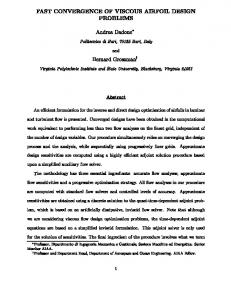
to be formed from a pair of standard telecom grade )bers of the type G.652, with core and cladding radii 4.5, 62:5 urn, respectively, n1 = 1:4518, n2 = 1:4473 and na = 1:0. The mode indices are evaluated for three inverse taper ratios, p (= tapered )ber radius/that of untapered )ber) =0 : 50, 0.35 and 0.05, for a moderately fused coupler having a degree of fusion, f = 0 : 5 , which is de)ned as f = (2b-d)/(2b(2-V2)) [8,20]. Fig. 5 depicts the dimensions and index distribution of the )ctitious waveguide in the backdrop of the coupler cross-section. Here 8n\ = n1 — n\ and 8n\ =n\ — n\ represent small index differences between the rectangular core and hypothetical waveguide used in the calculation of corrected mode-index [20]. Though the structure appears complex, its symmetry about x- and y-axis makes the algebra quite simple. Example )eld distributions of the fundamental and )rst-order modes (local modes) of this fused coupler generated by the perturbation method, using Eq. (1), are shown in Fig. 6(a) and (b). In Fig. 7(a) and (b), the true modal )elds after the convergence process are shown. These modes correspond to the cross-sectional point of the coupler waist at which the inverse taper ratio, p = 0:35. Evidently, the approximate fields differ more at the corner regions (sharply falling fields) where the index difference between the coupler and the pseudo-waveguide is high. However, the shape of the approximate )eld distribution as evaluated by Eq. (1) is close to that of the corresponding true mode of the real waveguide and has the correct signs of the )eld values over the cross-section (see Fig. 7). Thus, for any order of modes, lower or higher, the )eld calculation is fast requiring only a small correction in the )eld values (see Fig. 2(c), for example). The )eld convergence algorithm transforms an arbitrary )eld to a mode of waveguide and closer is the initial )eld distribution to the mode, faster is the convergence. Perturbation method itself is reasonably accurate and recently, it has been implemented to successfully interpret the variety of experimental results exhibited by fused coupler components [8]. Therefore, it is natural that the perturbation step forms good approximation as trial solution in the
20
K ; 5 o Wr 40 30 . y in (im 10 20
30
Iff x in (im H i
60
70
(b) Fig. 6. Approximate )eld distributions of the (a) fundamental and (b) )rst-order local modes of the fused coupler generated by the perturbation method, i.e., the modes of the approximated waveguide of Fig. 5.
70
'o60 ^ 30
10
30
40
v in (im
50
60
10
20
.
y m H-m
70
(a)
1 0 ^ 20
Wr 30
xm (im
60
10 20
50
30
60
70
40 . y in |im
70
(b) Fig. 7. The true modal )elds of the fused coupler as obtained after the convergence of the approximate )elds (Fig. 6) corresponding to p = 0:35 and f = 0:5: the local modes—(a) fundamental and (b) )rst order.
")ne-tuning" process of mode convergence and hence, reduces the computation time appreciably. Table 1 quanti)es this fact in terms of improvements in the accuracy of the effective indices of the modes at different stages of the algorithm. The results obtained from this method are then compared with the values already known from point matching method and analytical solution. We have also calculated the modes of the step-index channel waveguide and
66
P. Roy Chaudhuri et al./Optics & Laser Technology 37 (2004) 61-67
Table 1 Calculated mode neg values at different stages of the computation algorithm showing the improvement in effective indices along with the modal convergence Waveguide type
Graded index channel Step-index channel Parabolic index )ber Fused coupler p = 0.35. / = 0.5
X (urn)
0.6328 0.6328 1.170 1.310
Mode order
Marcatili's index
Perturbation corrected
After mode convergence
Difference
»effO
»effp
»effin
»effm — »effO
1.5200216 1.5221413 1.4488203 1.4461277 1.4460345
1.5219877 — 1.4469243 1.4467891
1.5203319 1.5220462 1.4488616 1.4473150 1.4472944
3e-04 9e-05 4e-05 1e-03 1e-03
0 0 0 0 1
»efSn — »effp
6e-05 4e-04 5e-04
Table 2 Comparison of calculated neg values of fundamental modes with those obtained by other methods, and computation times without and with perturbation method indicating the accuracy and e8ciency of present algorithm Waveguide type
X (urn)
Present method
Other methods
"effm
Method
Difference
Time t and tp without and with perturbation correction
«eff
5neB
t (s)
h (s)
(t - tp=t) x 100 (%)
Graded channel
0.6328
1.5203319
Point matching
1.5203348
3e-06
236
43
82
Step-index channel
0.6328
1.5220496
73
1.4488616
4e-06 1e-05 1e-06
71
1.170
1.5220501 1.5220376 1.4488627
259
Parabolic index fiber
Point matching BEM Analytical
298
86
71
Fused coupler p = 0.35, / = 0.5
1.310
1.4473150
Point matching BEM
1.4473127 1.4472981
3e-06 2e-05
517
169
67
a
Boundary element method did not work in the cases of graded channel waveguide and parabolic )ber since a large number of boundaries are needed to simulate graded pro)le and hence a huge number of unknowns are involved.
fused coupler cases, using a surface integral analysis with a constant boundary element [17]. All the calculations were carried out using a desktop PC (Intel P-4 1:8 GHz). The computation times recorded are (for full-domain calculation having grid-size varying from 0.5 to 5 urn with a zero boundary-)eld approximation) intended to appreciate the relative convergence e8ciency, and not absolute values as it may vary with one's programming skill. Table 2 shows a summary and comparison of these results. Evidently, they are in good agreement. Previously, we have applied this technique in investigating the polarization characteristics of highly birefringent asymmetric core index-guiding photonic crystal )ber (PCF). The study yielded a useful design recipe, which has been successfully implemented in realizing a high-birefringence PCF. The details of this work are reported inRef. [15]. The calculation of )elds of the slab modes using numerical method, offers an easy means to incorporate the approximate )elds into the array of refractive index pro)le needed for the convergence scan. This algorithm is particularly very useful for calculation of modes of slab waveguides with arbitrarily graded index pro)le or multilayered structures. Thus for the typical examples of a graded channel waveguide or the parabolic index )ber, the approximate )elds were generated by evaluating the corresponding axial
slab modes and multiplying them (Marcatili's )eld [21]). However, though perturbation correction method does not strictly apply in these cases, the initial value of effective index and )eld distribution of the corresponding mode are quite good approximation to yield the desired mode suf)ciently fast through )eld convergence technique. As described earlier, the method is also suitable for calculation of polarization effects. The algorithm is especially very useful for determining any higher-order modes by choosing appropriate order of x- and y-slab modes to yield the approximate )elds by the perturbation method. Thus, the method is quite simple and computationally e8cient for practical waveguide problems.
4. Conclusions The algorithm presented in this paper provides a simple technique to calculate both the )eld distribution and the corresponding mode indices of optical waveguides with twodimensional index distribution. Examples show the accuracy and e8ciency of the method agreeing well with the known solutions. Due to obvious reasons, the method is faster as compared to conventional )eld convergence techniques and is particularly useful for quick calculation of any higherorder modes, and birefringence characteristics. Since any
P. Roy Chaudhuri et al./Optics & Laser Technology 37 (2004) 61-67
guided wave analysis centers around the effective index and modal )eld distribution, the technique should be identically precise and e8cient in estimating other important properties, namely, dispersion, and mode effective area. Thus, the speed of convergence, accuracy, and ease of implementation of the method would be computationally demanding for modeling/simulation of practical guided wave components. Acknowledgements This work is partially supported by Optel Telecommunications Ltd, India. Part of the work was carried out in the Institute of Infocomm Research (I 2 R), Singapore. Authors would like to thank Prof. Cheng Tee Hiang of Lightwave Department, I2R, Singapore, for his encouragement. References [1] Chiang KS. Review of numerical and approximate methods for modal analysis of general optical dielectric waveguides. Opt Quantum Electron 1994;26:S113-34. [2] Kumar A, Thyagarajan K, Ghatak AK. Analysis of rectangular-core dielectric waveguides: an accurate perturbation approach. Opt Lett 1983;8:63-5. [3] Kumar A, Varshney RK. Propagation characteristics of highly elliptical core optical waveguide: a perturbation approach. Opt Quantum Electron 1984;16:349. [4] Kumar A, Varshney RK. Propagation characteristics of dual-mode elliptical-core optical )bers. Opt Lett 1989;14:817-9. [5] Kumar A, Shenoy MR, Thyagarajan K. Modes in anisotropic rectangular waveguides: an accurate and simple perturbation approach. IEEE Trans. Microwave Theory Tech. 1984;MTT-32: 1415- 8. [6] Varshney RK, Kumar A. A simple and accurate modal analysis of strip-loaded optical waveguides with various index pro)les. J Lightwave Technol 1988;LT-6:601-6.
67
[7] Kumar A, Kaul AN, Ghatak AK. Prediction of coupling length in a rectangular-core directional coupler: an accurate analysis. Opt Lett 1985;10:86-8. [8] Pal BP, Roy Chaudhuri P, Shenoy MR. FBT )ber coupler based components: process technology and a precise model for software-driven fabrication. Fiber Integrated Opt 2003;22:97-117. [9] Stern MS. Rayleigh quotient solution of semivectorial )eld problems for optical waveguides with arbitrary index pro)les. IEE Proc 1991;138:185-90. [10] Benson TM, Kendall PC, Stern MS, Quinney DA. New results for waveguide propagation constants. IEE Proc 1989;136:97-102. [11] Stern MS. Semivectorial polarised finite difference method for optical waveguides with arbitrary index pro)les. IEE Proc 1988; 135: 56-63. [12] Gonthier F, Lacroix S, Bures J. Numerical calculations of modes of optical waveguides with two-dimensional refractive index pro)les by a )eld correction method. Opt Quantum Electron 1994;26: S135-49. [13] Snyder AW, Love JD. Optical waveguide theory. London: Chapman & Hall; 1983. [14] Kawano K, Kitoh T. Introduction to optical waveguide analysis. New York: Wiley, 2001 (Chapter 4). [15] Roy Chaudhuri P, Zhao C, Paulose V, Hao J, Lu C. Investigating the characteristics of highly birefringent photonic crystal )ber using a semi-vectorial )eld convergence method. APOC'03 Conference 2-6 November 2003, Wuhan, China, paper 5279-02. [16] Soldano LB, Penning ECM. Optical multi-mode interference devices based on self-imaging: principles and applications. IEEE J Lightwave Technol 1995;13:615-27. [17] Guan N, Habu S, Takenaga K, Himeno K, Wada A. Boundary element method for analysis of holey optical )bers. IEEE J Lightwave Technol 2003;21:1787-92. [18] Meunier JP, Pigeon J, Massot JN. An e8cient method for calculating cutoff frequencies in optical fibers with arbitrary index profiles. J Lightwave Technol 1984;LT-2:171-5. [19] Van de Velde K, Thienpont H, Van Geen R. Extending the effective index method for arbitrarily shaped inhomogeneous optical waveguides. IEEE J Lightwave Technol 1988;6:1153-9. [20] Lacroix S, Gonthier F, Bures J. Modeling of symmetric 2 x 2 fused-)ber couplers. Appl Opt 1994;33:8361-9. [21] Marcatili EAJ. Dielectric rectangular waveguide and directional coupler for integrated optics. Bell Syst Tech J 1969;48:2071.