Fast Direct GPS Signal Acquisition Using FPGA Jing Pang∗ Abstract − This paper presents a novel P-code generator design strategy and direct GPS P-code acquisition technique. This method not only helps software simulation and simplifies FPGA hardware design, but also greatly decreases the acquisition time. The method was implemented on Xilinx VirtexE FPGA chip and tested on GPS data.
1
INTRODUCTION
Global Positioning System (GPS) signal acquisition process is a two-dimensional (code and frequency) search in order to synchronize the GPS receiver replica code and the carrier frequency [1]. Traditionally, C/A code can be quickly and easily acquired, and is used as a hand over for P-code acquisition [2]. Compared with C/A code, which is available on the L1 frequency, P-code is available on both L1 and L2. P-code is much faster and provides more accurate positioning precision service. Also, when L2 carrier is jammed, direct P-code acquisition is the only solution to acquire GPS signal. However, the disadvantage of longer codes is longer acquisition time. A fast searching strategy is necessary to decrease acquisition time. The reported direct GPS P-code acquisition algorithms are based on either time domain correlators or FFT search. The direct P-code acquisition in time domain needs massive physical correlators in parallel for code search [3], which requires lots of resources for hardware implementation. Other attempts include FFT search, such as double block and zero padding, pseudo circular data approach [4], circular correlation by partition and zero padding method [5], and extended replica folding acquisitions [6]. Software based signal processing algorithms are the major concerns of these approaches. They usually involve a large size FFT, which may not cause problem in software simulation, but it is not an easy task in hardware design because of the design complexities and large hardware resources used. This paper presents a new method to design P-code generator. The period of P-code is one week long, which is a challenge for the P-code related research. The availability of P-code from any moment of a week is very useful for both GPS P-code related software simulation research and hardware design. Moreover, a new averaging method using small size
∗
Janusz Starzyk* FFT is presented to achieve fast P-code acquisition especially used for FPGA hardware design. In section 2 the architecture and the formulas to set up P-code generator registers are discussed. The property of P-code and the direct P-code acquisition method are described in sections 3 and 4 respectively. The hardware architecture is presented in section 5. Conclusions are outlined in section 6. 2
P-CODE GENERATOR
P-code generator structure is shown in Figure 1 [7]. Each Pi (t) is the Modulo-2 sum of X 1 and
X 2 i clocked at 10.23 Mbps. X1A, X1B, X2A and X2B are 12-stage LFSRs (linear feedback shift registers). X1A and X2A are each shorted to 4092 chips. X1B and X2B are each shorted to 4093 chips. X 1 is generated by the Modulo-2 sum of the outputs of X1A and X1B. When the X1A short cycles are counted to 3750, the X1 epoch is generated. The X2A and X2B shift registers operate in a similar manner. The Modulo-2 sum of the outputs of X2A and X2B produce X 2 sequence, which is delayed by i chips ranging from 1 to 37 [7]. At the beginning of the GPS weekly period, X1A, X1B, X2A and X2B LFSRs are initialized. During the last X1A period of the GPS week interval, X1B, X2A and X2B are held when reaching the last state of their respective cycles until the X1A cycle is completed. Then all of them are initialized for the first chip of the new week. At any specific time during a week, the number of chips N generated by X1A generator can be easily calculated because the clock frequency is equal to 10.23MHz. Then the number of chips can be described in equation (1).
N = Time [s] *10.23 [MHz]
(1) In order to initialize P-code generator in a specific time during a week, integer y1a is used to load the zcounter. Integers x1a and x2a are used to load the 3750 division counters in X1A and X2A blocks. Integers x1b and x2b are used to load the 3749 division counters in X1B and X2B blocks. Integers z1a, z1b, z2a and z2b are used to initialize four linear feedback shift registers. Integer dv is used to load the delay by 37 chips block. Integers y2a and m
School of Electrical Engineering and Computer Science, Ohio University, Athens, OH 45701, email:
[email protected],
[email protected], tel: (740)593-1580, fax: (740)593-0007.
dv = m − C1 when m ≥ C1 = 0, otherwise z 2a = Re m[(m − dv ) mod 4092] x 2a = (m − dv − z 2a ) / 4092 z 2b = 4092 when m ≥ C 2 = Re m(m mod 4093), otherwise x 2b = 3748 when m ≥ C 2 = (m − z 2b) / 4093, otherwise
are only needed to compute register values. In addition, two constants are defined as
C1 = 4092 * 3750 C 2 = 4093 * 3749 10.23MHz
(1) (2) X1EPOCH
X1A LFSR
4092 decoder
Clock control
HALT
X1B LFSR
3749
RESUME
X2EPOC H OR
X1A(12) X1B(12) X2A(12) X2B(12)
37
HALT
Clock control
3
3750
4092 decoder
XOR
ENDWEEK
XOR
X2
XOR SHIFT 1 REGISTER i 37
X2i
Figure 1. P-code generator diagram Several equations involving the chip number can be formulated to relate those integers. For instance, z1a, x1a and y1a can be obtained for (3) (4) (5)
(6) Similarly,
N = C1* y1a + 4093 * x1b + z1b (7) (8) N = (C1 + 37) * y 2a + 4092 * x 2a + z 2a + dv N = (C1 + 37) * y 2a + 4093 * x 2b + z 2b (9) The solutions of equations (7), (8) and (9) are as following: z1b = 4092 when ( N − C 1 * y1a ) ≥ C 2 , (10) = Re m [( N − C 1 * y1a ) mod 4093 ], otherwise x1b = 3748 when ( N − C 1 * y1a ) ≥ C 2, = ( N − z1b − C 1 * y1a ) / 4093 , otherwise
m = Re m[N mod (C1 + 37)] y 2a = (N − m ) / (C1 + 37 )
∞
∫ P (t )P (t + τ )dt i
i
(19)
−∞
…
N = C1* y1a + 4092 * x1a + z1a where z1a = Re m[N mod 4092] x1a = Re m{[(N − z1a ) / 4092] mod 3750} y1a = ( N − z1a − 4092 * x1a ) / C1
(18)
P-CODE PROPERTY
RP (τ ) =
3749
X1
(17)
Each satellite uses unique P-codes to implement the CDMA technique. The autocorrelation function of Pcodes is
ST ARTWEEK
Pi 4093 decoder
(15) (16)
Solving these equations sets initial values of registers required to generate a specific segment of the P-code.
7day ENDW EEK reset HALT
Clock control
X2B LFSR
Z-counter 403200
4093 decoder
X2A LFSR
3750 RESUME
(14)
(11) (12) (13)
where Pi is the P-code from the ith satellite and τ is phase of the time shift. The correlation peaks repeat every code period. The property of the autocorrelation is used to synchronize the receiverreplicated code with the received signal. It is important that the cross-correlation of any two Pcodes is minimal for any phase or Doppler shift over the entire code period. The cross-correlation function is defined by
Rij (τ ) =
∞
∫ P (t )P (t + τ )dt = 0 i
j
(20)
−∞
where Pi is the P-code from the ith satellite and Pj from the jth satellite where i ≠ j . It is well known that the linear correlation of periodic codes can be performed by circular convolution. Since the period of whole P-code is one week, the segment of P-code can be considered as non-periodic code. As a result, zero padding must be combined with circular convolution to get correct correlation results for non-periodic codes. The autocorrelation plot of segments of P-codes has a big peak and relative small side lobes. So segments of Pcodes are almost orthogonal to each other. 4
DIRECT P-CODE ACQUISITION
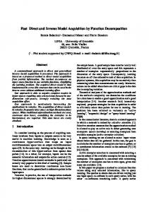
After GPS signals are demodulated, a fast correlation method has to be found to do code phase search. Average method is proposed here to speed up the correlation. Suppose GPS signals are down converted to 12.5MHz and the sampling frequency is 65.536 MHz. This satisfies Nyquist’s sampling requirement because P-code has a bandwidth of 20.46 MHz. Let’s
see how the direct average method affects the P-code autocorrelation function. First, average every 128 samples to generate 1024 points in 2ms and call them target 1. To obtain target 2, use the first 512 points from target 1 and then pad another half with 512 zeros. Calculate 1024-point FFT for target 1 signals, and then calculate the conjugate of the target 2 1024-point FFT results. Next multiply these results together. At last take 1024-point IFFT. Keep only the first half IFFT results and discard the other half. The final results correspond to the correlation results in the first millisecond. Shift the target 1 and target 2 signals by 1ms and repeat the autocorrelation procedure for the second millisecond. In this way, get autocorrelation function of each millisecond in 15 ms and sum them together. Figure 2 illustrates the autocorrelation result in 15 ms using the above average method. dire c t avera ge metho d: a utoc orre latio n re sult
400
S amp ling freq uen cy: 65.5 36 M Hz 350
autocorrelation
300 250 200 150 100 50 0 0
100
2 00
3 00
400
500
600
Figure 2. Direct average autocorrelation result The term acquisition margin is defined here as the ratio of the largest peak divided by the second peak for the averaged P-code signals. 40
direct average method: acquisition margin distribution over 1s Sampling frequency: 65.536 MHz code phase shift: 0
acquisition margin
35
phase search in different milliseconds. The acquisition procedure based on this method is as following: Step 1: Calculate the cross correlation of GPS samples with locally generated P-code samples using average method. Similarly, the correlation results over 15 ms need to be added together. Step 2: If a correlation is not detected, shift P-code samples by 1 ms as reference. Repeat step 1~ step 9 until acquiring correlation peak. Step 3: If a correlation peak is detected at location m, the signal is acquired. The peak location has a code phase resolution of 128 samples. Step 4: Shift signal by (m-1)*128 samples. Use circular convolution combined with zero padding to get correlation results. Then use (m*128+n-128) to get exact sample location. 5 DESIGN FLOW ARCHITECTURE
HARDWARE
The design flow shown in Figure 4 starts with RTL design entry and synthesis using Xilinx Foundation Tools. Both must be tested by functional simulation. Then FPGA mapping, placement and routing are performed, which are constrained by timing conditions and verified by timing simulation. The final generated bit file is loaded onto FPGA board by user developed C++ program. This design work used FPGA board developed by Nallatech with Xilinx PCI preconfigured firmware and Nallatech PCI bridge interface. Nallatech also provides DLL software interface for user C++ program to communicate with VirtexE chip by PCI bus. Design Entry Functional Simulation Synthesis
Mapping Placement Routing
30
AND
User C++ Application
Nallatech DLL Software Interface Timing Simulation
Nallatech Custom Hardware Interface
25
Bit File
20
Figure 4. Design flow diagram
15 10 0
VirtexE chip
200
400 600 time(ms)
800
1000
Figure 3. Direct average method: acquisition margin distribution over 1s Figure 2 shows that averaged chunks of data are basically orthogonal to each other. The mean value of the acquisition margin in Figure 3 is around 26.882 and the variation value is 2.676. As a result, the average method is statistically valid to be used in code
GPS signal has 131,072 samples in 2ms. Averaging by 128 is taken to make 1024 points. It saves lots of computational effort going from 131,072 point FFT to 1024 point FFT. The result changes the code phase resolution to 128 samples. The local reference is the averaged P-code. Once GPS signal is acquired, an extra 1024-point correlation without averaging needs to be taken around the acquired sample location so that the code phase resolution can be adjusted to be within ± ½ chip. The architecture is illustrated in Figure 5.
search is less than 10,000 clock cycles, which takes 0.25ms on a system with clock frequency of 40 MHz.
Average GPS
IFFT
FFT
Signal
Average
6 FFT
Local reference
NCO
Control & decision logic Maximum peak selection
2
||
Figure 5. Direct GPS P-code acquisition using direct average method Averaging raises the noise floor due to the increased cross-correlation between averaged GPS signals and local reference. Proper correlation energy makeup strategy must be considered such as block processing technique [8] to increase the signal to noise ratio. But when a fast acquisition is the major concern in strong GPS signal applications, the direct average method greatly simplifies the hardware design. It achieves fast acquisition due to the decreased computation loads. The architecture is implemented on Xilinx FPGA VirtexE xcv1600E chip. The implementation cost is listed in the following table. 1
2
3
4
5
6
7
8
CLB slices
68
182
25
1866
1866
559
386
55
Block Rams
0
0
0
16
16
0
0
0
Note: 1. NCO 2. P-code generator 3. Average 4. FFT 5. IFFT 6. Complex conjugate multiplication 7. Correlation amplitude square 8. Peak selection and decision logic Total available CLB slices: 15552 Total available Block Rams: 144 Table 1. VirtexE FPGA design cost If those blocks inside the dashed line are replaced by Block RAMs to store the FFT results of the demodulated and averaged GPS samples, then the implementation cost is 36 out of 144 Block Rams (25%), 5008 out of 15552 (32%) configurable logic block (CLB) slices. The total cost including the implementation of those blocks inside the dashed line will be about 6943 CLB slices (44.6%), and 52 Block Rams (36.1%). The whole code phase search time over 15 ms GPS samples including FFT/IFFT and acquisition peak
CONCLUSIONS
This paper introduces the mathematical models to facilitate the P-code generator design, which can produce P-code starting from any time of a week. In addition, this paper proposes the new direct averaging method especially used for FPGA hardware design. Compared with massive physical correlators [3] for code search and other extremely large FFT search methods [4][5], the FPGA hardware design for the algorithm we proposed is greatly simplified and the acquisition speed is improved.. The design was successfully implemented on Xilinx VirtexE chip and tested on GPS data sent from PC through PCI bus. References
[1] M.S. Braasch, A. J. van Dierendonck, “GPS receiver architectures and measurements”, Proceedings of the IEEE, vol. 87/1, Jan. 1999. [2] C. Yang, “Sequential Block Search for Direct Acquisition of Long Codes under Large Uncertainty”, ION NTM 2001, Jan. 22-24, 2001, Long Beach, CA. [3] R. Wolfert, S. Chen, S. Kohli, D. Leimer, J. Lascody, “Rapid Direct P(Y)-Code Acquisition In a Hostile Environment”, Proc. of IEEE PLANS, April 1998. [4] David M. Lin, James B. Y. Tsui, Dana Howell, “Direct P(Y)-Code Acquisition Algorithm for Software GPS Receivers”, Proc. ION GPS, 1999. [5] David M. Lin, James B. Y. Tsui, “Comparison of Acquisition Methods for Software GPS Receiver”, Proc. of ION GPS, 2000. [6] C. Yang, J. Chaffee, J. Abel, J. Vasquez, “Extended Replica Folding for Direct Acquisition of GPS P-Code And Its Performance Analysis”, Proc. ION GPS 2000, 19-22 Sep, 2000, Salt Lake City, Utah. [7] “Global Positioning System Interface Control Document”, ICD-GPS-200c, available at http://www.spacecom.af.mil/usspace/gps_support/ documents/ICD-GPS-200RC-004.pdf [8] Maarten Uijt Haag, “An Investigation into the application of block processing techniques for the global positioning system”, August, 1999. [9] The Programmable Logic Data Book, Xilinx Publication, 2002.