Fast Image Mapping of Endoscopic Image Mosaics with Three-Dimensional Ultrasound Image for Intrauterine Treatment of Twin-to-Twin Transfusion Syndrome Hongen Liao1,2, Masayoshi Tsuzuki1, Etsuko Kobayashi1, Takeyoshi Dohi3, Toshio Chiba4, Takashi Mochizuki5, and Ichiro Sakuma1 1
Graduate School of Engineering, The University of Tokyo Translational Systems Biology and Medicine Initiative, The University of Tokyo 3 Graduate School of Information Science and Technology, The University of Tokyo 4 National Center for Child Health and Development, Japan 5 Aloka Co., LTD., Japan 7-3-1 Hongo, Bunkyo-ku, Tokyo 113-8656, Japan
[email protected]
2
Abstract. This paper describes a fast image mapping system that integrates endoscopic image mosaics with three-dimensional (3-D) ultrasound images for assisting intrauterine treatment of twin-to-twin transfusion syndrome (TTTS) by laser photocoagulation. Endoscopic laser photocoagulation treatment has a good survival rate and a low complication rate for twins. However, the small field of view and lack of surrounding information makes the identification of vessels anastomosis difficult. We have developed an extended placenta visualization system with the fusion of endoscopic image mosaics with a 3-D ultrasoundimage placenta model. Fully automatic and fast calibration is used for endoscope calibration in fluid. The 3-D spatial position of the endoscopic images and the ultrasound image are tracked by a 3-D position tracking device. The mosaiced endoscope images are registered to the surface of the 3-D ultrasound placenta model by using a fast GPU-based image rendering method. Experimental results show that the system may provide an improved and efficient way of planning and guidance in laser photocoagulation TTTS treatment.
1 Introduction Twin-to-twin transfusion syndrome (TTTS) is a disease of the placenta that affects identical twins or higher multiple pregnancies where two or more fetuses share a common (monochorionic) placenta [1-2]. The syndrome occurrs in the vascular communications between the fetuses in a monochorionic gestation. Although each fetus uses its side of the placenta, the blood vessels connecting the twins allow blood to pass from one twin to the other. This serious condition occurs when the shared placenta contains abnormal blood vessels that connect the twins, resulting in an imbalanced blood between the twins. The implication of this condition is that one fetus (the recipient) may get too much blood, thereby overloading his or her cardiovascular T. Dohi, I. Sakuma, and H. Liao (Eds.): MIAR 2008, LNCS 5128, pp. 329–338, 2008. © Springer-Verlag Berlin Heidelberg 2008
330
H. Liao et al.
system, while the other fetus (the donor) may experience an inadequate supply of blood. If not treated, TTTS may be life-threatening to both the fetuses, and those who survive may suffer from many serious health problems. Several techniques have been developed for treatment of TTTS. Surgical treatments include amniotic septostomy, amnio reduction, and laser photocoagulation. Obliteration of the vessels can halt the pathophysiologic process. Laser photocoagulation is a useful method, which has a good survival rate and a low complication rate [3]. In this method, a laser fiber and an endoscope are inserted into the uterus. With the guidance of ultrasound and direct video, specific vessels that cause the blood-sharing problem are coagulated using a laser light beam to stop the imbalanced flow of blood between the twins [4]. Thus precision in laser treatment requires the accurate vessels position information. Advances in ultrasound and endoscopic techniques and devices have aided the identification and treatment of this potentially lethal condition. In laser photocoagulation treatment, the connecting vessels are identified by visual measurement based on endoscopic images. However, the small field of view, as well as the lack of image depth and surrounding information make it difficult for the surgeon to grasp the whole information of the placenta and decide whether the blood vessel being observed is one of the connecting vessels or not. As a result, surgical success relies on the surgeon’s ability to memorize the blood vasculatory system on the placenta surface, a task that leaves the risk of missing some connecting vessels. Quintero et al. compared the selective laser photocoagulation with non-selective laser photocoagulation [5]. The selective laser photocoagulation of communicating vessels is a valuable application of minimally invasive endoscopic intrauterine surgery. The fusion of intra-operative endoscopic images and pre- or intra- operative threedimensional (3-D) data has the potential to lead to minimally invasive fetal surgery. Dey et al. described the automatic fusion of endoscopic images to the surface of a 3-D model derived from pre-operative data [6]. Szpala et al. demonstrated the real-time fusion of endoscopic views with dynamic 3-D cardiac images [7] and Reeff et al. developed a mosaicing method for endoscopic placenta images [8]. To improve the safety and accuracy of laser photocoagulation treatment for TTTS, we have developed an image mapping system for the intra-operative fusion of endoscopic images to a 3D placenta model derived from ultrasound data. Our system provides an easy and fast way to obtain an intra-operative overall image of the placenta and enables the surgeon to identify connecting vessels three-dimensionally. Experimental results show that this image mapping system will give a promising support to surgeons performing laser photocoagulation treatment.
2 System and Methods 2.1 Procedure and Requirements of Laser Photocoagulation Treatment of TTTS In the treatment of TTTS, the placenta is inspected with a very thin endoscope, which is commonly called a “fetoscope”. With expectant mother under general anesthesia, the scope is placed into the uterus through a tiny hole in the abdomen. The small
Fast Image Mapping of Endoscopic Image Mosaics
331
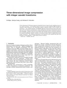
connecting blood vessels can then be visualized and “coagulated” using laser light from a small optic fiber passed inside or outside of the scope. The connecting blood vessels on the surface of the placenta are closed by the precision-guided laser light so that the fetuses’ blood is no longer shared with each other (Fig.1). The procedure of laser photocoagulation treatment of TTTS is as follows. 1) Insert the fetoscopic instrument into the uterus (womb) through a small incision at a suitable position relative to that of the fetuses and placenta under the guidance of ultrasound. 2) Locate the recipient twin first and then the donor twin or “stuck twin”, which is enveloped by a membrane. 3) Search the placenta for communicating (shared) vessels and identify vascular anatomoses. 4) Map the placenta for the abnormal vessels with a guiding light and use a laser to coagulate the vessels. 5) After a review of all of the lasered vessels, finish the treatment and exit the uterus.
Fig. 1. Laser photocoagulation treatment for TTTS
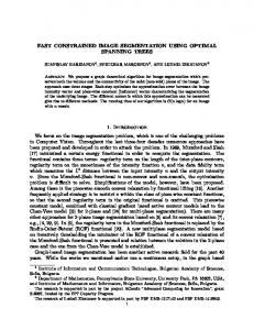
The procedure for identifying the abnormal connections is not so easy. The endoscope has a small field of view and the obtained images with severe lens distortions suffer from weak visibility in the amniotic fluid. This makes it difficult for the surgeon to ensure that all the abnormal vascular connections have been found and treated accordingly. Precision in laser treatment requires the accurate 3-D position information, as well as the ability to view the placenta and the corresponding vessels panoramically. 2.2 System Configuration Our image mapping system consists of an endoscope, an ultrasound device, a 3-D position tracking system, and a computer (Fig.2). The endoscope captures images of the placenta surface, and the ultrasound is used to obtain images of the intra-operative placenta. The 3-D position tracking system (POLARIS Vicra, NDI, Canada) provides the position and orientation of the endoscope and the ultrasound probe. Optical tracking markers are attached to the shaft of the endoscope and the ultrasound probe. The position and orientation of the probe are used to estimate the position and orientation of placenta model. The image distortion is corrected to make the endoscope images to be mapped without distortion. The corresponding positions of points on image data and placenta model are calculated to map the images onto the placenta. The mapping results of endoscopic images and 3-D object model can be displayed three-dimensionally.
332
H. Liao et al.
Fig. 2. System configuration for mapping endoscopic image mosaic with 3-D placenta model derived from ultrasound images
2.3 Endoscope Calibration and Image Correction Camera calibration is performed by observing an object whose geometry in 3-D space is known with good precision. The calibration is performed in water simulating amniotic fluid since the focal length will be changed by the refractive index of the medium. A test pattern image is used in the calibration of endoscope. Correction of endoscope images is performed only to the captured area with a circle shape. We use an active contour method [9] to extract the image area. Since the active contour is greatly affected by image noise, we pass the image through a low-pass filter of fast Fourier transformation (FFT) and then apply a Gaussian filter onto the image to blur the image to reduce the noise influence. The fish-eye lens in the endoscope’s camera produces a barrel-type spatial distortion due to its wide-angle configuration. Compensation for the distortion of the image is required in image mapping to enable accurate measurement and registration [10]. To correct the image distortion, we calculate the positions of point where lines intersect on the captured image with those on a test pattern image and find the equation that describes the relationship between them. The position of each point on the captured image is measured from the optical center, which is found with the use of a low-power laser beam. The camera parameters and equations that describe the relationship of the calibration are used to correct the position of every point on the captured endoscopic image. 2.4 Ultrasound Image Calibration and Surface Extraction To map the mosaics of endoscopic images with the surface of the object, we first acquire 3-D intra-operative data from the ultrasound device (ProSound α 10, Aloka Co., LTD.). We use a 3-D ultrasound probe with the volume data acquisition rate of 2 volumes per second. Coordinate transformation and image enhancement are performed as 3-D data preprocessing. To track the position and orientation of the ultrasound images with respect to transmitter reference coordinate system, we mount an optical position-tracking tool on the ultrasound probe. The 3-D spatial position of ultrasound data is calibrated with a set of metal balls which can be observed clearly
Fast Image Mapping of Endoscopic Image Mosaics
333
with the ultrasound device. We calibrate the position of the metal balls in the ultrasound images. Their exact positions are measured with the same optical tracking system. Consider the coordinates of a set of N corresponding points (balls) in two different coordinate spaces. The objective is to determine a geometric transformation that associates the two coordinate spaces. The relationship of the ultrasound coordinate and the mounted optical tracking tool can thus be derived from the corresponding transformation. An interpolation profile is used to improve coordinate transformation performance. We implemented a 3-D diffusion stick filter for speckle suppression to enhance image quality. The surface of the placenta is extracted from the 3-D ultrasound data with 3D Slicer based software and the surface configuration is converted to polygon triangle patches by using VTK and polygon reduction algorithms. 2.5 Registration of Endoscopic Image onto 3-D Ultrasound Model After obtaining the endoscopic image area and correcting the image distortion, we map the image data onto the placenta model. Image mapping is typically used to map 2-D images to the surface of 3-D objects [11]. To map an image to a surface, the correct image coordinates for the vertex of each polygon must be computed. The relationships of the coordinates are shown in Fig. 3. For image mapping, the calibration and registration process is as follows. For calibration of an ultrasound image, we achieve the relationship between the ultrasound probe and the coordinate of the volume data: 1) Register 3-D ultrasound image data to reproduce the reconstruction volume for placenta model representation with the coordinate system of C. Calculate the positions of metal balls in ultrasound images, producing transformation BCT . 2) Calibrate the rigid body of the optical position markers attached to the ultrasound probe, R0, relative to the optical tracking system, P0, by RP0 T . Mark the fiducial 0
markers (metal balls), B, with a tracked pointer to indicate their position with respect to the physical space of metal balls, producing transformation PB0 T . Then we can get the relationship between the metal balls and the ultrasound probe RB0 T as shown in Fig. 3. The ultrasound probe and the coordinate of the volume data is therefore given by RCT = BCT RB0T = BC T PB0T RP0T . 0
For ultrasound images, a real-time tracking of the optical markers mounted on the ultrasound probe give the following transformations: 3) Calculate the rigid body motion of the optical position markers attached to the ultrasound probe, R, relative to the optical tracking system, P, by PRT . Then we can get the transformation PCT = PRT RCT For endoscope images, we attach another set of optical position markers to the shaft of the endoscope and calculate the position and orientation of the camera lens: 4) Using transformation EPT , calculate the rigid body motion of the optical position markers attached to the endoscope, E, relative to the optical tracking system, P.
334
H. Liao et al.
5) Calculate the position and the six degrees of freedom of the endoscope’s pinhole camera using the transformation VET , the tracking position markers attached to the endoscope and the coordinates associated with the endoscope lens. For the image mapping, we can project the endoscope image onto the 3-D ultrasound model and map the image to the corresponding polygon triangle patches: 6) The projection image of the endoscope for mapping is therefore given by IV =VET EPT PCTC =VET EPT PRT RCTC
Fig. 3. Geometrical framework for mapping 2-D endoscopic images to 3-D model
2.6 GPU-Based Fast Image Mapping Once we know the relationship between the focal point of the endoscope and the corresponding projected polygon triangle patches on the placenta model, we map every pixel in the image data onto the triangle patches through the focal point of the endoscope, assuming the endoscope can be represented as a pinhole camera model. To map every image pixel, first we calculate the vector between the focal point and pixel position. Using this vector, we calculate the position of every image pixel on the plane of a triangle patch and check whether the position is inside the triangle patch or not. If the position is inside the triangle patch, we check whether the vector comes to the front or back of the triangle patch. The corresponding position of the image pixel on the placenta model is found when the vector comes to the front of the triangle patch. Tiling multiple images is a viable way to build a high-resolution and wide-area imaging system. However, aligning and synthesizing a seamless image become a challenge when the endoscopic images are used. For alignment, the endoscopic images for mapping are projected onto the surface of the placenta model with a panoramic image mosaic [12], and seamless processing is accomplished by geometrical correction and color modulation [13]. Coordinate transformation, median filtering, and mapping is implemented with GPU acceleration using Compute Unified Device Architecture (CUDA). Image process for mapping an endoscopic image onto the surface of the ultrasound 3-D model takes less than 10 milliseconds.
Fast Image Mapping of Endoscopic Image Mosaics
335
3 Experiments and Results 3.1 Ultrasound Calibration We used a Polaris Vicra optical position tracking system to track the position of the endoscope and the probe of the ultrasound. The system includes a computer for integrating the position information of the captured endoscopic image and the 3-D ultrasound data of the object. In order to establish transformation of the coordinate of the ultrasound probe and the volume data described in subsections 2.4 and 2.5, we manufactured a phantom with four metal balls set in different planes and calibrated the positions both of the ultrasound image and physical space. For image acquisition, an optical pointer pivoted to obtain an accurate estimate of the desired 3-D point was used to collect 3-D points of each metal ball for offline processing. The transformation matrices were derived from the relative transformations between the balls of the calibration phantom with a positional offset on the basis of the pixel coordination of the phantom in the acquired ultrasound image. 3.2 Accuracy Measurement of Image Calibrations and Image Mapping We used a phantom with a set of test pattern lattices. The phantom includes a grid of several crossing threads with different colors for identification of the endoscopic images and the accurate measurement of image mapping. Each thread is placed and intersected to be a check-pattern with an interval of 2 cm. An agar mixed with graphite, which can be observed by ultrasound clearly, was closely placed under the thread grid. The check-pattern thread phantom was placed in a water container (Fig. 4a). The 3-D structure of the phantom (Fig. 4b) was acquired with the ultrasound device and generated a 3-D model with polygon triangle patches (Fig. 4d) using the algorithms mentioned in subsection 2.4. The image of the phantom was also captured by the endoscope (Fig. 4c). We first evaluated the accuracy of the ultrasound image by measuring of the positions of the intersecting thread in ultrasound images. The average error for 36 (6x6 threads) measured points was about 2 mm. Next, we mapped the corrected endoscopic images to the surface model of the phantom. The image mapping system was evaluated by calculating the intersected point of the threads both in the ultrasound model and the endoscope mapping results. The average error for 36 points was 2.8 mm and the standard deviation was 1.51 mm. The experimental results showed that the image mapping system is effective for providing a high-precision large-scale image of the endoscope image mapping 3-D model.
(a)
(b)
(c)
(d)
Fig. 4. Experimental devices and test pattern phantom: (a) Experimental setup. (b) Ultrasound image. (c) Endoscope images. (d) Surface model of phantom.
336
H. Liao et al.
3.3 Placenta Model Experiment We used a placenta model with red and blue vessels simulating veins and arteries to test our placenta mapping system. The placenta model was placed into a container simulating a uterus. The image of the placenta was captured by the endoscope (Fig. 5).The structure of the placenta was acquired by ultrasound image (Fig. 6a) and a 3-D model with polygon triangle patches was generated (Fig. 6b). We corrected the captured endoscope images and performed image mapping onto the 3-D placenta model. The adjacent image maps onto the model were overlaid each other (Fig. 7a). The image could not be observed smoothly without correction. We mosaiced the endoscope images and used alignment information, geometric correction and color modulation so that the image looked seamless, as if projected from a single source (Fig. 7b). The procedure for mapping five endoscope images to the 3-D surface model took less than 50 milliseconds.
Fig. 5. Captured endoscopic images
(a)
(b)
Fig. 6. (a) Ultrasound images and (b) 3-D model generated from ultrasound images
(a)
(b)
Fig. 7. Mosaics of panoramic endoscope image are mapped on the 3-D ultrasound model. (a) Without seamless processing. (b) With seamless processing; the extended endoscopic-imagemapped 3-D placenta is viewed from different directions.
Fast Image Mapping of Endoscopic Image Mosaics
337
The image mapping results show that the developed image mapping system can generate a large-scale high-quality 3-D placenta and help surgeon to get the information in convenient way, which could provide the overall image of placenta and help the surgeon in performing identification of connecting vessels.
4 Discussion and Conclusion We developed an image mapping system for automatically creating a 3-D structure of the entire placenta with high-quality and panoramic endoscopic image surface mapping. We demonstrated that the system can provide significantly enlarged view of the placenta, which would be very useful for surgeons to identify connecting vessels and execute laser photocoagulation treatment. The image mapping system can provide 3-D images of the entire placenta, which enables surgeons to observe the vessels on the placenta of twins without any need for memorization. The image mapping accuracy was 2.8 mm on average, which could be improved by increasing the tracking accuracy of the ultrasound probe and the endoscope. One solution would be to calibrate the position and the orientation of the endoscope lens by using another tracking system, such as an electromagnetic measurement system. Since the position of the placenta can change during the image acquisition, how to reduce the influence of the movement in intra-operative measurement of the placenta is another challenge. Our future work includes improving the accuracy of the image mapping and the quality of the resultant images. The quality of mapped image could be improved by image enhancement techniques to get a clearer endoscopic image and by color-shading correction for the inhomogeneous light distribution of the light source. We plan to test the system in an in-vivo experiment and improve the speed of placenta segmentation from ultrasound images, which will be especially important in the clinical implementation. In conclusion, we developed a placenta mapping system for the treatment of TTTS. The image mapping system can provide 3-D large-scale images of the placenta surface, which enables surgeon to observe the vasculatory system of the twins without any need for memorizing it. This can reduce the risk of missing important vessels in the treatment. With the improvement of the image mapping accuracy and image quality, the system should be of practical use in laser photocoagulation TTTS treatment.
Acknowledgment This work was supported in part by Health and Labor Sciences Research Grants of Ministry of Health, Labor and Welfare in Japan, Special Coordination Funds for Promoting Science and Technology commissioned by the Ministry of Education, Culture, Sports, Science and Technology in Japan, and Grant for Industrial Technology Research of New Energy and Industrial Technology Development Organization, Japan.
338
H. Liao et al.
References 1. Bruner, J.P., Rosemond, R.L.: Twin-to-twin transfusion syndrome: A subset of the twin oligohydramnios-polyhydramnois sequence. Am. J. Obstet. Gynecol. 169, 925–930 (1993) 2. Bruner, J.P., Anderson, T.L., Rosemond, R.L.: Placental pathophysiology of the twin-totwin transfusion syndrome. Placenta 19, 81–86 (1996) 3. Hecher, K., et al.: Endoscopic laser surgery versus serial amniocenteses in the treatment of severe twin-twin transfusion syndrome. Am. J. Obstet. Gynecol. 180, 717–724 (1999) 4. Lia, J.E.D., Cruikshank, D.P., Keye, W.R.: Fetoscopic neodymium: YAG laser occlusion of placental vessels in severe twin-twin transfusion syndrome. Obstetrics & Gynecology 75, 1046–1053 (1990) 5. Quintero, R.A., Comas, C., Bornick, P.W., Allen, M.H., Kruger, M.: Selective verus nonselective laser photocoagulation of placental vessels in twin-twin transfusion syndrome. Ultrasound Obstet Gynecol. 16, 230–236 (2000) 6. Dey, D., Gobbi, D.G., Slomka, P.J., Surry, K.J.M., Peters, T.M.: Automatic fusion of freehand endoscopic brain images to three-dimensional surfaces creating stereoscopic panoramas. IEEE Trans. Medical Imaging 21(1), 23–30 (2002) 7. Szpala, S., Wierzbicki, M., Guiraudon, G., Peters, T.M.: Real-Time Fusion of Endoscopic Views with Dynamic 3-D Cardiac Images: A Phantom Stugy. IEEE Trans. Medical Imaging 24(9), 1207–1215 (2005) 8. Reeff, M., Gerhard, F., Cattin, P., Székely, G.: Mosaicing of Endoscopic Placenta Images. GI Jahrestagung (1), 467–474 (2006) 9. Williams, D., Shah, M.: A fast algorithm for active contours and curvature estimation. CVGIP: Image Understanding 55, 14–26 (1992) 10. Shah, S., Aggarwal, J.K.: A Simple Calibration Procedure for Fish-Eye (High Distortion) Lens Camera. In: IEEE Intl. Conference on Robotics and Automation, vol. 4, pp. 3422– 3427 (1994) 11. Heckbert, P.: Survey of texture mapping. IEEE Computer Graphics and Applications, 56– 67 (1986) 12. Szeliski, R.: Video Mosaics for Virtual Environments. IEEE Computer Graphics and Applications (March 1996) 13. Liao, H., Iwahara, M., Koike, T., Hata, N., Sakuma, I., Dohi, T.: Scalable high-resolution integral videography autostereoscopic display by use of seamless multi-projection. Applied Optics 44(3), 305–315 (2005)