namics, large deformation, soft body, domain embedding, free- form deformation ... We address this problem by demonstrating how lattice shape matching can ...
FastLSM: Fast Lattice Shape Matching for Robust Real-Time Deformation Alec R. Rivers Doug L. James Cornell University
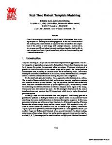
Figure 1: Real-time Peng-chinko! (Left) 150 cartoon penguins deforming dynamically using Fast Lattice Shape Matching (FastLSM); (Right) Deformed lattices consisting of 150 particles per penguin (22,500 particles total). Using FastLSM, these penguins can be deformed robustly at real-time gaming rates (25 FPS, simulation cost of 0.28 ms/object; Pentium4 3.4 GHz; w = 2). Note: in these timings penguins collide with icicles but not with each other.
Abstract
1
We introduce a simple technique that enables robust approximation of volumetric, large-deformation dynamics for real-time or largescale offline simulations. We propose Lattice Shape Matching, an extension of deformable shape matching to regular lattices with embedded geometry; lattice vertices are smoothed by convolution of rigid shape matching operators on local lattice regions, with the effective mechanical stiffness specified by the amount of smoothing via region width. Since the na¨ıve method can be very slow for stiff models – per-vertex costs scale cubically with region width – we provide a fast summation algorithm, Fast Lattice Shape Matching (FastLSM), that exploits the inherent summation redundancy of shape matching and can provide large-region matching at constant per-vertex cost. With this approach, large lattices can be simulated in linear time. We present several examples and benchmarks of an efficient CPU implementation, including many dozens of soft bodies simulated at real-time rates on a typical desktop machine.
Interactive simulation of large-deformation dynamics is an old and important problem in computer graphics. Unfortunately, the intrinsic difficulty of large-deformation physical simulation is confounding for real-time simulation: many proposed methods are simply not robust or fast enough to be employed in actual real-time applications such as interactive virtual environments. Furthermore, other systems that are fast enough typically achieve this speed at the cost of introducing various restrictions, such as limiting the range of possible deformations or user interactions, requiring specialized hardware or resources, or precluding runtime modifications such as cutting or smashing. In addition, many techniques are quite complex, making them difficult to implement. We present a geometrically based approach that seeks to address these simulation concerns. Our system performs at very fast interactive rates on desktop computers, supports a substantial range of deformation for detailed geometric models, and is visually plausible even under large external forces. Our approach can take any mesh as input, requires no manual preprocessing, and supports dynamic model modifications (such as fracture) as an easy extension. It is also unconditionally stable, and easy to implement. Our approach begins by applying the deformable shape matching dynamics of M¨uller and colleagues [2005] to regular (cubic) lattices via a region-based convolution. We use rigid shape matching transforms that use regional estimates of rotation and translation at every lattice location to provide detailed deformation smoothing without domain boundary artifacts. Increasing the shape matching region width increases the smoothing, which effectively approximates more rigid models (see Figure 2). The method provides a simple framework that is robust by construction. However, na¨ıve lattice shape matching with even modest filter widths is expensive, and cost increases cubically with width. We address this problem by demonstrating how lattice shape matching can be achieved efficiently at cost linear in the size of the lattice, and effectively independent of the region size. This lat-
CR Categories: I.3.5 [Computer Graphics]: Computational Geometry and Object Modeling—Physically based modeling Keywords: Fast summation, summed-area tables, interactive dynamics, large deformation, soft body, domain embedding, freeform deformation, shape matching, polar decomposition, video game physics, fracturing
Introduction
Figure 2: Increasing shape-matching region width increases stiffness: (Top) larger half-width, w, values correspond to (Bottom) faster deformation smoothing and larger effective stiffness. Each hexagon represents a shape matching particle set. Particles are shown at the positions they would take after two steps of smoothing the perturbation.
ter point means that both stiff and soft models can be time-stepped at similar costs. In Section 3 we illustrate the inter-region similarity of shape matching summations, and show how this can be exploited to construct a linear-time fast summation algorithm for Fast Lattice Shape Matching (FastLSM). We use the fast summation technique both to estimate the rigid shape matching transforms from lattice positions and to distribute their smoothing influences on the lattice to obtain goal positions for the particles, which are used to drive dynamics as in [M¨uller et al. 2005]. Our optimization is conceptually similar to Crow’s classical summed-area tables result that enables fast linear-time image convolution for box filters [Crow 1984; Hensley et al. 2005], or the restructuring of fast median and bilateral filtering pixel kernels to exploit redundancy for improved performance [Weiss 2006]. In Section 4 we present a number of extensions that improve the usefulness and speed of the technique. In particular, we address how to approximate the high number of polar decompositions required by our system, introduce techniques to support damping and fracturing, and describe efficient hardware rendering. Other related work: Given the substantial work on deformable models, we refer the reader to surveys of the field [Gibson and Mirtich 1997; Nealen et al. 2005] and focus here on closely related works. Lattice-based shape deformers, such as classical free-form deformation, are commonplace in graphics and cleanly separate deformation modeling complexity from geometric complexity and surface representation [Sederberg and Parry 1986; Coquillart 1990; MacCracken and Joy 1996; Westermann and Rezk-Salama 2001]. Related physically based dynamic deformation models are widely used to animate embedded geometry [Faloutsos et al. 1997; Gibson and Mirtich 1997]; common lattice embeddings such as regular voxels [M¨uller et al. 2004; James et al. 2004] or BCC tetrahedral meshes [Molino et al. 2004] can simplify meshing issues for simulation, especially during fracture. Unfortunately, detailed discrete approximations of volumetric deformation are expensive to simulate, prohibitively so for many real-time applications. Detailed lattice-based FEM meshes are used in character animation [Sifakis et al. 2005], but mostly for offline simulations. Avoiding element recomputation costs is possible using rotated linear element models [M¨uller et al. 2002; Capell et al. 2002], but integrating large-deformation dynamics often involves significant costs for semi-implicit integration and algebraic linear system solves. Adaptive meshing and sophisticated spacetime adaptive simulation methods can reduce this problem somewhat [Debunne et al. 2001; Grinspun et al. 2002; Capell et al. 2002], but this speed tradeoff comes at the cost of simplifying deformations and increasing implementation complexity. Improved speed
and robustness can be achieved by other dimensional model reduction techniques, such as precomputation-based subspace integration methods [Barbiˇc and James 2005], but these can also limit deformation complexity since dimensional model reduction may restrict deformations to a non-optimal low-dimensional subspace. Another serious issue when simulating volumetric deformable models, especially with collisions, is robustness. It is unclear whether many of these methods are robust enough for “generalpurpose abuse” in video games. Simple lattice deformers such as ChainMail [Gibson and Mirtich 1997] provide speed and robustness, but suffer from limited realism. Invertible finite elements provide robustness for very challenging simulations [Irving et al. 2004], and particle-based approaches are versatile [Wicke et al. 2006], but neither are fast enough for real-time simulation. By relaxing physical consistency, so-called meshless deformations based on shape matching (of rigid, affine and quadratic deformation models of constant deformation complexity) can deliver both excellent speed and robustness suitable for video games [M¨uller et al. 2005], as well as physical plausibility for modest deformation complexities. While more detailed displacement fields can be approximated using multiple overlapping domains, the resulting deformation model can suffer from blending artifacts from the domain influences. Lattice shape matching (LSM) addresses the problem of blending artifacts by using a regular lattice with as many overlapping domains as cells (see Figure 3). Unfortunately, this exacerbates the issue that deformable shape matching is computationally inefficient for many domains; we address this by exploiting the regular lattice definition to construct a fast summation algorithm. Our contributions: • Lattice Shape Matching, a volumetric lattice-based formulation of deformable shape matching for robust dynamic deformation of embedded meshes; • A linear-time fast summation algorithm for lattice shape matching (FastLSM); • Practical enhancements such as for fast rotation estimation, hardware rendering, and fast-summation damping.
2
Lattice Shape Matching
We now define the lattice representation of objects in our system and present notation used throughout, and go on to show how to apply rigid shape matching to overlapping lattice domains to yield our unoptimized dynamic deformation model. Lattice construction: Given a surface mesh to be deformed, we conservatively voxelize the model to construct a lattice of cubic cells containing the mesh, with solid objects appropriately flood filled [James et al. 2004]. The embedded mesh is then deformed using trilinear interpolation of lattice vertex positions. Lattice deformation is controlled by unit point-mass particles placed at the lattice cell vertices. Each lattice vertex and particle share an equivalent index, i. For each particle i, let its static initial (material) position be x0i , its dynamic position be xi , and its mass be mi . For each particle i, we construct its one-ring neighborhood list Ni comprised of particles sharing at least one lattice cell with particle i. Shape matching regions: Each particle i is associated with a shape matching region comprised of a set of shape matching particles, Ri , which for half-width w contains i and all particles reachable by traversing not more than w neighborhood lists from particle i; e.g., if w = 1 then Ri = Ni . Here w is the region half-width (or `∞ radius) that is given as input to the system. This definition of Ri allows irregular shape matching regions and handles boundary cases. In the common case where particles are maximally connected, regions will be cubes of side length 2w + 1. Note that shape matching sets need not be unique, and Ri = R j for i 6= j is common at
3
boundaries. Finally, for each particle i, the set of indices of all shape matching regions to which i belongs is equivalent to Ri . Dynamics: The dynamics of a lattice shape matching region are similar to the rigid case of [M¨uller et al. 2005], except that there are multiple overlapping shape matching regions. At each time step, each region r finds the best rigid transform to match the initial particle positions (x0i )i∈Rr to their deformed positions (xi )i∈Rr , thus determining a per-region least-squares rotation and translation of the rest positions, Tr = [Rr tr ] ∈ R3×4 . To ensure that particles belonging to many regions are not weighted more than others, we use modified particle masses, m˜ i = mi / |Ri |, for shape matching. This transformed rest configuration is then used to assign goal positions to each particle with respect to the region r (see Figure 2), with each particle i computing its final goal position as the average of regional goal positions, gi =< Tr x0i >r∈Ri . Finally, particle positions xi and velocities vi are updated using the goal positions gi as in [M¨uller et al. 2005]: vi (t + h)
=
xi (t + h)
=
gi (t) − xi (t) fext (t) +h h mi xi (t) + h vi (t + h)
vi (t) +
A na¨ıve implementation of lattice shape matching involves O(w3 ) flops per lattice node, as each region will contain on the order of w3 particles. Fortunately, simple optimizations can reduce this to a small O(1) cost in practice (see Figure 4). Our optimizations rely on a specialized shape matching algorithm that maximizes calculation reuse between regions. This is achieved by restating the position and rotational components of each region’s best fit transformation in terms of simple summations of a property (e.g., xi ) over the particles in each region. (How the rotation estimation is amenable to linear summations is described in Section 3.2.) Because these summations are dependent only on the particles, and not on what region is performing the shape matching, summations can be computed just once for any set of particles and then reused by all regions that contain that set. Because regions are densely packed and overlapping, the summation reuse will be high.
Figure 4: Cost complexity versus region width, w, per simulation particle: the O(w3 ) na¨ıve brute-force approach; our O(w) bar-plate-cube approach; and our O(1) FastLSM approach. FastLSM speedups are noticeable even for small w values. Data is for solid buddha model. Cost is measured in units of FastLSM(w=1) ≈ FastLSM(w), and illustrates hundredfold speedups over the na¨ıve approach for moderate w.
150 O(w3 ) naive O(w) bar−plate−cube O(1) F as tLS M
100 C OS T
Figure 3: Comparison of shape matching methods under extreme deformation:(Left) Linear and (Middle) quadratic shape matching with a low number of regions; (Right) lattice shape matching.
Linear-Time Fast Summation Algorithm
50
0 1
(1)
2
3
4 w
5
6
7
(2)
3.1 Behavior and tuning: Although LSM utilizes only rigid transformations per shape matching region, there are many regularly overlapping regions, and the resulting system can consequently have high-degree-of-freedom motions with minimal region blending discontinuities (see Figure 3). Physical constants such as the center of mass and angular momentum of an object are conserved due to the properties of the shape matching algorithm, which ensure that the best-fit goal positions will share the same center of mass as the particles’ actual positions, and that the rotation will be a least squares best fit and therefore introduce no net torque [M¨uller et al. 2005]. If the shape matching forces are repeatedly applied with no external forces, the local-frame displacement field will smooth out as the object returns to its rest configuration (up to a global rigid transformation). In this way, the geometrically based models we simulate are analogous to elastically deformable models. The rigidity of the object can be adjusted using the region halfwidth parameter, w ∈ {1, 2, . . .}. Smoothing performed with small regions (small w) will spread perturbations slowly, causing the material to appear floppy. Conversely, large shape matching regions smooth deformations more, and quickly return the object to its rest configuration (see Figure 2). This approach is general, capable of simulating objects from any surface mesh, and, as a shape matching-based approach, is unconditionally stable. The approach is capable of simulating increasingly rigid objects by increasing the region size. It also has the advantage of requiring no manual preprocessing, unless the user wishes to specify particle-specific values for mi , which can be made easier by attaching values to the vertices of the surface mesh and having particles assume the values of the nearest surface mesh vertex.
Fast Summation
We now present a method of breaking down the particle lists Rr into sub-summations that will be maximally reused between regions. We can then quickly sum any particle-defined value vi over all the particles i ∈ Rr for all Rr by building up and reusing these sub-summations, rather than computing the sums over all particles in each region separately. By decomposing the list of parent regions Ri for each particle in the same way, we can also efficiently sum any region-defined value vr over all the regions r ∈ Ri for all Ri . This fast summation is the basis for our system’s high speed.
Figure 5: Decomposing a region summation into sub-summations for reuse across regions (w = 1 case).
Simple perfect-cube case: The main idea of our summation algorithm can be illustrated most easily for the simple case of cubical regions. In the common non-boundary case where the surrounding particles are maximally connected, a region r of half-width w that is centered around the particle at a generalized index r = xyz will be a (2w + 1) × (2w + 1) × (2w + 1) cube – a 3 × 3 cube for w = 1 (see Figure 5). The summation of a particle-defined value v is, in
Rotations: Following [M¨uller et al. 2005], we estimate the least squares rotation Rr for particles Rr using the rotational part of
an obvious notation, equivalent to z+w
y+w
x+w
∑
∑
∑
SUMr =
vi jk =
k=z−w j=y−w i=x−w
z+w
y+w
∑
∑
k=z−w
j=y−w
!!
x+w
.
vi jk
∑
(3) These inner summations can be broken out and calculated for each location in the lattice, allowing us to reuse the values between regions. We are then able to build up the final region summations SUMr in three global passes: y+w
x+w
Xxyz =
∑
viyz ⇒ XYxyz =
{z
z+w
Xx jz ⇒ SUMr =
j=y−w
i=x−w
|
∑
}
|
Sum over X (→Bars)
{z
∑
XYxyk
(4)
k=z−w
}
Sum over Y (→Plates)
|
Ar ≡
i=x−w
{z
∑
m˜ i (xi − cr )(x0i − c0r )T ∈ R3×3 ,
� � where c0r = ∑i∈Rr m˜ i x0i /Mr is the precomputed center of mass of region r’s undeformed particles. We obtain the rotational part using the polar decomposition A = RU, where U is a unique 3-by-3 symmetric stretch matrix [Golub and Van Loan 1996]. Unfortunately, (10) is not directly amenable to fast summation since the summand is a function of both particle i and region r. We isolate these dependencies by expanding (10) and simplifying common terms:
}
Sum over Z (→Cubes)
Ar
=
∑
T
m˜ i (xi x0i ) − (
i∈Rr
Linear-time approach: The total cost of calculating these values for every index in the lattice will be 3n(2w + 1) flops, as opposed to n(2w + 1)3 flops for the na¨ıve approach that treats each region sum independently, where n is the number of lattice indices. However, we can do even better than O(w) flops per lattice index when we observe these summation recurrences: Xxyz
=
X(x−1)yz − v(x−w−1)yz + v(x+w)yz
(5)
XYxyz
=
XYx(y−1)z − Xx(y−w−1)z + Xx(y+w)z
(6)
SUMxyz
=
SUMxy(z−1) − XYxy(z−w−1) + XYxy(z+w)
(7)
Using these definitions, the summation requires constant time per lattice index: only 6 flops. Consequently, lattice summations can be performed in time linear in the number of lattice indices, and independent of the size of w to leading order (see Figure 4). Handling irregular regions: To extend this simplified approach to handle cases where not all regions are perfect cubes, we record r and XY r . for each region r region-specific sub-summations Xxyz xyz These sums consist of the particles that would be in the corresponding generic sub-summations Xxyz and XYxyz but are restricted to particles in Rr . At lattice generation time, we generate these sub-summations for r into w XY r summations along each region r by splitting SUMxyz xyz r summation into w X r the z axis, and then splitting each XYxyz xyz summations along the y axis. We then collapse identical sets; often for each index xyz there will exist only one unique Xxyz and XYxyz . Fast summation operator: To indicate that the sum of a field vi over i ∈ Rr is performed using the fast summation algorithm, we introduce this operator notation: n o F vi ≡ ∑ vi (using multi-pass fast summation). (8) i∈Rr
3.2
(10)
i∈Rr
i∈Rr
Shape Matching using Fast Summations
In this section we show how the shape matching operation can be accelerated by expressing computations in terms of summations that can leverage the fast summation operator. We describe efficient calculations for each region r’s center of mass cr and least-squares rotation Rr (which determine each region’s optimal rigid transformation Tr ) and each particle i’s goal position gi . Center of mass: We obtain the deformed center of mass for each region r as follows: n o 1 cr = F m˜ i xi (9) Mr i∈Rr where Mr = ∑i∈Rr m˜ i is the precomputed effective region mass. The calculation of cr can be performed efficiently by using the fastsummation algorithm to calculate the regional sums of m˜ i xi .
=
∑
T
m˜ i (xi x0i ) − (
i∈Rr
(
∑
F
m˜ i xi )(
∑
m˜ i xi )(
i∈Rr
∑
∑
T
m˜ i x0i ) + Mr cr c0r
T
i∈Rr
i∈Rr
i∈Rr
=
T
m˜ i xi )c0r − cr (
∑
i∈Rr
∑
T
m˜ i x0i )/Mr −
i∈Rr
T
m˜ i x0i )/Mr + (
i∈Rr
∑
m˜ i xi )(
i∈Rr
n o T T m˜ i xi x0i − Mr cr c0r
∑
T
m˜ i x0i )/Mr
i∈Rr
(11)
Given that cr and c0r are already available (c0r is precomputed), only the fast summation over m˜ i xi (x0i )T is required for efficient calculation of Rr . Rigid transformations: Each region’s least-squares rigid transformation of the rest positions x0i is a rotation by Rr and a translation that shifts the rotated c0r to cr . This transformation is stored as the matrix Tr = [Rr (cr − Rr c0r )] ∈ R3×4 . Goal positions: Each particle’s goal position gi can be restated as the transformation of the particle’s rest position, x0i , by the average rigid transformation over the regions the particle belongs to, gi =
1 |Ri |
F r∈R
i
n o Tr x0i .
(12)
FastLSM algorithm: The overall simulation algorithm for deformable shape matching dynamics is as follows: FAST LSM() 1 Precompute Mr , c0r for all regions 2 while true n o n o T 0 3 Calculate F m˜ i xi , F m˜ i xi xi for all r i∈Rr i∈Rr 4 for each region r 5 Calculate cr using (9) 6 Calculate Ar using (11) 7 Polar decompose Ar = Rr Ur � (13) 8 Calculate Tr = [Rr cr −Rr c0r ] n o 9 Calculate F Tr for all i r∈Ri 10 for each particle i 11 Calculate gi using (12) 12 Calculate vi (t + h) using (1) 13 Perform damping (see §4) 14 for each particle i 15 Calculate xi (t + h) using (2)
4
Extensions
Fast polar decompositions are required for efficient rotation extraction from many thousands of A matrices per frame to enable detailed lattices. Like [M¨uller et al. 2005], we use cyclic Jacobi iterations to diagonalize AT A = U2 = V diag(λ )V T to construct
R = AU−1 . However, doing this na¨ıvely would limit FastLSM to modest lattices, and fewer objects. To address this limitation, we cache each region’s stretch eigenvectors V¯ from the last timestep, and use these to provide a “warm start” (see [Golub and Van Loan 1996]): we initialize with V = V¯ and begin Jacobi sweeps on V¯ T U2V¯ , which during temporally coherent phases is nearly diagonal. With cold starts (V = I) we observed average behavior of 1.9 Jacobi sweeps/solution, resulting in a total of 2,500 ns/decomposition, which was a system bottleneck – note that even in undeformed configurations, A is not approximately the identity matrix. However, with caching of stretch eigenvectors, we required only 0.4 Jacobi sweeps on average per solution, resulting in a cost decrease to 450 ns/decomposition and removing the system bottleneck. The exact savings depend upon the degree of rotational temporal coherence. Finally, we experimented with state-of-the-art fast polar decomposition algorithms for 3×3 matrices [Kopp 2006], but despite being slightly faster they were not sufficiently robust.
Damping can be approximated using a fast summation extension of the method introduced by M¨uller et al. [2006]. In that paper, least squares is used to fit an instantaneous rigid motion to the particles; particle velocities are then filtered by attenuating velocity deviations from the spatial rigid motion by a factor k ∈ [0, 1) at each time step. As an alternative to global damping of nonrigid motion, we can apply damping on a per-region basis, bleeding off non-rigid motion of local regions. A key observation that makes this efficient is that the estimate of region r’s rigid-body velocity, (vr , ωr = I−1 r Lr ), is decomposable into fast-summation passes (reusing prior values), n o 1 vr = F m˜ i vi (14) Mr i∈Rr o n o n Lr = F m˜ i x˜ i vi − Mr c˜ r vr , Ir = F m˜ i x˜ i x˜ Ti − Mr c˜ r c˜ Tr . i∈Rr
i∈Rr
Using fast summations, this damping model requires roughly the same number of flops as the shape matching operation. Furthermore, for interactive applications this operation can produce convincing results even if applied only every, e.g., third frame.
Fracture: Our fast summation method is flexible enough to be
(where ∇ = ∂∂X ) to transform surface tangent vectors as follows. Note that F introduces shear, so that the undeformed vertex normal, N, maps to FN which is no longer normal to the deformed surface. However, undeformed tangent vectors are mapped by F to deformed tangents. Therefore, given N, we precompute mutually orthonormal tangent vectors, U and V, and can then transform them using F to obtain the new tangent vectors u and v as weighted combinations of the eight lattice positions, u = FU =
∑
(u)
αi
xI(i)
where α (u) = U · ∇φi (X)
(17)
i=1..8 (v)
and similarly, v = ∑i=1..8 αi xI(i) . The shader then computes these u and v linear combinations to obtain the deformed normal as n = normalize(u × v). Our vertex shader implementation uses precomputed (x) (u) (v) {I(i), αi , αi , αi }i=1..8 , or eight 4-vectors per vertex. Finally, since hardware restricts the number of uniform/constant memory positions indexable by any shaded vertex, during precomputation we greedily construct triangle batches renderable using common lattice positions of suitably bounded size. The inset buddha image shows colored triangle batches, with associated lattice points shown for one batch.
5
Results
Model statistics and algorithm timings are provided in Table 1. All timings were generated on a Pentium IV 3.4 GHz machine with a GeForce 7800. The per-vertex complexity of our algorithm is illustrated empirically in Figure 4. Real-time demonstrations of the system for modest lattices suitable for gaming applications are shown in Figure 1. High-resolution models are shown in Figure 6. Please see our accompanying video for animations of our system in use; additional materials and demonstrations are available at http://www.graphics.cornell.edu/projects/FastLSM
applied to lattices undergoing fracture. To illustrate this, we use a classic approximation wherein links between any neighboring particles (i, j) whose distance exceeds a preset strain limit are simply broken [Terzopoulos and Fleischer 1988]. We then update the locally affected per-region summation sets to reflect this change. A prototype example of this approach is shown inset; better renderings are possible by updating the embedded surface mesh using results of prior work [M¨uller et al. 2004; Molino et al. 2004].
Hardware-accelerated rendering is desirable for the deformation and rendering of complex lattice-embedded geometry. We therefore briefly outline an optimized vertex shader. Lattice particle positions are copied to uniform/constant GPU memory, so that each deformed vertex position x can be computed as the weighted combination of its eight lattice-cell positions, x = x(X) =
∑
φi (X) xI(i) =
i=1..8
∑
(x)
αi
xI(i) ,
(15)
i=1..8
(x)
where αi ≡ φi (X) are trilinear interpolation weights for the vertex’s material position, X, and I(i) are the indices of the positions in constant memory. Per-vertex normals are slightly trickier. We use the per-vertex deformation gradient, F = ∇ x(X) =
∑
i=1..8
xI(i) ∇φi (X)
(16)
Figure 6: High-resolution examples: (Left) Solid buddha model deforms at 1 FPS, and (Middle) shell model deforms at 2 FPS (both with 10 timesteps/frame, and self-collision processing); (Right) Infant model with rigid skeleton deforms at 20 FPS (3 timesteps/frame).
6
Conclusion and Discussion
We have presented Lattice Shape Matching and an optimized fast summation algorithm, FastLSM, for dynamic deformations that emphasize visual plausibility and large deformations while maintaining the speed and simplicity of geometrically based approaches. We have demonstrated an efficient implementation that can simulate a large number of objects convincingly on a desktop machine. Our system can handle a wide range of possible deformations, but may produce non-physical behavior in some circumstances as
Model Penguin Buddha (solid) Buddha (shell) Infant (without bones)
# Triangles
# Particles
# Regions
w
9,874 200,000 200,000 16,844
150 57,626 19,959 2,570
130 57,626 19,959 2,506
2 1 1 2
Fast Sum (%) 0.03 ms 31.62 ms 10.15 ms 0.51 ms
(12%) (18%) (20%) (10%)
Shape Matching (%)
Polar Decomp (%)
0.07 ms 29.36 ms 10.48 ms 0.10 ms
0.10 ms 31.66 ms 4.02 ms 1.17 ms
(26%) (17%) (21%) (19%)
(36%) (18%) (8%) (23%)
Damping (%) – 51.29 ms 17.08 ms 1.50 ms
(30%) (35%) (30%)
Total Time 0.28 ms 167.83 ms 48.47 ms 4.99 ms
Table 1: Model statistics and simulation timings: Percentages are of simulation time, with missing percentage points from simulation
overhead. Identical regions are collapsed, leading to fewer unique regions than particles.
a result of its geometrically motivated approach. This makes it unsuitable for applications requiring precise or predictive modeling. Future work includes exploring different particle frameworks, including tetrahedral lattices or irregular samplings. Reducing the resolution of particles or regions in the object interior could speed performance without seriously altering the visual behavior, and could still be written to take advantage of the calculation reuse and fast summation methods that are the core of our system. FastLSM provides an efficient orientation-sensitive smoothing operator that might find other uses in geometric modeling. Acknowledgments: The authors wish to acknowledge the help of Calen Pennington, Jonathan Grassi, David Rosen, Jernej Barbiˇc, and Christopher Cameron; The Stanford 3D Scanning Repository for the buddha mesh; the infant model was provided courtesy of Zygote Media Group, Inc. and 3DScience.com. The second author was supported in part by the National Science Foundation (CAREER-0430528, CompBio-0621999), National Institutes of Health (NIH R01EB006615), the Alfred P. Sloan Foundation, The Boeing Company, Pixar, and NVIDIA.
References BARBI Cˇ , J., AND JAMES , D. 2005. Real-Time Subspace Integration for St. Venant-Kirchhoff Deformable Models. ACM Trans. on Graphics 24, 3 (Aug.), 982–990. C APELL , S., G REEN , S., C URLESS , B., D UCHAMP, T., AND P OPOVI C´ , Z. 2002. Interactive Skeleton-Driven Dynamic Deformations. ACM Trans. on Graphics 21, 3 (July), 586–593. C OQUILLART, S. 1990. Extended Free-Form Deformation: A Sculpturing Tool for 3D Geometric Modeling. In Computer Graphics (Proc. of SIGGRAPH 90), vol. 24, 187–196. C ROW, F. C. 1984. Summed-area Tables for Texture Mapping. In Computer Graphics (Proc. of SIGGRAPH 84), vol. 18, 207–212. D EBUNNE , G., D ESBRUN , M., C ANI , M.-P., AND BARR , A. H. 2001. Dynamic Real-Time Deformations Using Space & Time Adaptive Sampling. In Proc. of ACM SIGGRAPH 2001, 31–36. FALOUTSOS , P., VAN DE PANNE , M., AND T ERZOPOULOS , D. 1997. Dynamic Free-Form Deformations for Animation Synthesis. IEEE Trans. on Visualization and Computer Graphics 3, 3 (July - September), 201–214. G IBSON , S. F., AND M IRTICH , B. 1997. A Survey of Deformable Models in Computer Graphics. Tech. Rep. TR-97-19, Mitsubishi Electric Research Laboratories, Cambridge, MA, November. G OLUB , G., AND VAN L OAN , C. 1996. Matrix Computations, third ed. The Johns Hopkins University Press, Baltimore. ¨ G RINSPUN , E., K RYSL , P., AND S CHR ODER , P. 2002. CHARMS: A Simple Framework for Adaptive Simulation. ACM Trans. on Graphics 21, 3 (July), 281–290. H ENSLEY, J., S CHEUERMANN , T., C OOMBE , G., S INGH , M., AND L ASTRA , A. 2005. Fast Summed-Area Table Generation and its Applications. Computer Graphics Forum 24, 3, 547–556.
I RVING , G., T ERAN , J., AND F EDKIW, R. 2004. Invertible finite elements for robust simulation of large deformation. In 2004 ACM SIGGRAPH / Eurographics Symposium on Computer Animation, 131–140. JAMES , D. L., BARBI Cˇ , J., AND T WIGG , C. D. 2004. Squashing Cubes: Automating Deformable Model Construction for Graphics. In Proc. of the SIGGRAPH 2004 Conference on Sketches & Applications, ACM Press. KOPP, J., 2006. Efficient numerical diagonalization of Hermitian 3x3 matrices. arXiv:physics/0610206v1 [physics.comp-ph]. M AC C RACKEN , R., AND J OY, K. I. 1996. Free-Form Deformations with Lattices of Arbitrary Topology. In Proc. of SIGGRAPH 96, Computer Graphics Proc., 181–188. M OLINO , N., BAO , Z., AND F EDKIW, R. 2004. A virtual node algorithm for changing mesh topology during simulation. ACM Trans. on Graphics 23, 3 (Aug.), 385–392. ¨ M ULLER , M., D ORSEY, J., M C M ILLAN , L., JAGNOW, R., AND C UTLER , B. 2002. Stable Real-Time Deformations. In ACM SIGGRAPH Symposium on Computer Animation, 49–54. ¨ M ULLER , M., T ESCHNER , M., AND G ROSS , M. 2004. Physically based simulation of objects represented by surface meshes. In Proc. of Computer Graphics International (CGI), 26–33. ¨ M ULLER , M., H EIDELBERGER , B., T ESCHNER , M., AND G ROSS , M. 2005. Meshless Deformations Based on Shape Matching. ACM Trans. on Graphics 24, 3 (Aug.), 471–478. ¨ M ULLER , M., H EIDELBERGER , B., H ENNIX , M., AND R ATCLIFF , J. 2006. Position Based Dynamics. In Proc. of Virtual Reality Interactions and Physical Simulations (VRIPhys), 71–80. N EALEN , A., M ULLER , M., K EISER , R., B OXERMAN , E., AND C ARLSON , M. 2005. Physically based deformable models in computer graphics. In Eurographics: State of the Art Report. S EDERBERG , T. W., AND PARRY, S. R. 1986. Free-Form Deformation of Solid Geometric Models. In Computer Graphics (Proc. SIGGRAPH 86), vol. 20, 151–160. S IFAKIS , E., N EVEROV, I., AND F EDKIW, R. 2005. Automatic determination of facial muscle activations from sparse motion capture marker data. ACM Trans. on Graphics 24, 3, 417–425. T ERZOPOULOS , D., AND F LEISCHER , K. 1988. Deformable models. The Visual Computer 4, 6 (Dec.), 306–331. W EISS , B. 2006. Fast Median and Bilateral Filtering. ACM Trans. on Graphics 25, 3 (July), 519–526. W ESTERMANN , R., AND R EZK -S ALAMA , C. 2001. Real-Time Volume Deformations. Comp. Graph. Forum 20, 3, 443–451. W ICKE , M., H ATT, P., PAULY, M., M UELLER , M., AND G ROSS , M. 2006. Versatile virtual materials using implicit connectivity. In Eurographics Symposium on Point-Based Graphics, Boston, USA, 29-30 July, 73–82.


![[ujm-00374332, v1] Fast and Robust Image Matching ... - CiteSeerX](https://m.moam.info/img/260x300/ujm-00374332-v1-fast-and-robust-image-matching-cit_59e3c5ad1723dde4690ae2c0.jpg)


