environments to repair each component failure in the robot, the .... ers, algorithms have been developed which reconfigure the data or code ..... Radiation hard-.
1
Fault Detection and Fault Tolerance in Robotics
Monica Visinsky, Ian D. Walker, and Joseph R. Cavallaro Department of Electrical & Computer Engineering Rice University Houston, TX 77251-1892
2
1
INTRODUCTION
Abstract Robots are used in inaccessible or hazardous environments in order to alleviate some of the time, cost and risk involved in preparing men to endure these conditions. In order to perform their expected tasks, the robots are often quite complex, thus increasing their potential for failures. If men must be sent into these environments to repair each component failure in the robot, the advantages of using the robot are quickly lost. Fault tolerant robots are needed which can effectively cope with failures and continue their tasks until repairs can be realistically scheduled. Before fault tolerant capabilities can be created, methods of detecting and pinpointing failures must be perfected. This paper develops a basic fault tree analysis of a robot in order to obtain a better understanding of where failures can occur and how they contribute to other failures in the robot. The resulting failure flow chart can also be used to analyze the resiliency of the robot in the presence of specific faults. By simulating robot failures and fault detection schemes, the problems involved in detecting failures for robots are explored in more depth. Future work will extend the analyses done in this paper to enhance Trick, a robotic simulation testbed, with fault tolerant capabilities in an expert system package.
1
Introduction
In hazardous environments or environments which are not readily accessible to man, robots must be able to efficiently adapt to failures in both software and hardware in order to continue working until the problem can be realistically repaired. Before a robot can try to cope with a failure, however, it must first be able to detect and pinpoint the problem. This paper develops a basic fault tree analysis of robots in order to obtain a better understanding of where failures can occur and how they contribute to other failures or limitations in each robot. The resulting flow chart style picture of failures in a robot can also be used to analyze the resiliency of the robot in the presence of specific faults. Once a failure has been detected, the robot can reorganize its view of its internal structure in such a way as to hide or isolate the fault so the robot can continue working. The focus of this research is on finding real-time fault detection and fault tolerance methods which maintain as much of the robot’s functionality as possible while not requiring that redundant or extra parts be added to the robot.
1.1 1.1.1
Previous Work Redundancy Based Fault Tolerance
Previous work on fault tolerance in robotics has concentrated on dealing with faults in one specific part of the robot (mechanical
1.1
Previous Work
3
failure in the motor, kinematic joint failure, etc.) with only token thought going to the more critical, systemwide effect of the failures. Relatively little focus has been given to the question of how to detect failures in robots. Previous research tends to concentrate on fault tolerance algorithms, especially those schemes which rely on duplicating parts such as joint motors [13, 16] for their fault tolerant abilities. These redundancy based schemes are similar to several computer fault tolerant algorithms which are also based on redundancy of parts. One common computer fault tolerant algorithm is Triple Modular Redundancy (TMR) in which three processors all work on the same problem and compare their results. If one of the processors is faulty and its result does not agree with the results of the other two processors, the faulty processor is voted out of the final decision and the correct result is passed on to the rest of the system. This fault tolerance scheme fails, however, if more than one of the processors is faulty. Duplication of physical parts provides a backup in case the element performing the work fails. Redundancy of parts can also provide a useful means of checking to see if a component is in error. For the equivalent redundancy based robot fault tolerant algorithms, two motors have been placed in each robot joint to provide a backup in case one motor stalls, runs away, or begins free-spinning. The fault tolerant advantages of redundancy has also led to adding extra parallel structures, such as seven legs when only six are needed, in order to allow many different configurations in the presence of a failure. Previous work by Tesar, et al at UT, Austin [13] and independently by Wu [16] with Lockheed at Johnson Space Center have explored the aforementioned method of duplicating motors. Two motors in a joint work together so as to provide one output velocity for the joint. When one of the motors breaks, the other one takes over the faulty motor’s functions. The faulty motor must be isolated from the system or the second motor must be able to adjust its output to account for any transients introduced to the system by the failed motor. If the robot is performing a timecritical or delicate task, fault tolerance must allow the robot to get a run-away motor (which could cause drastic changes in the robot’s motion) under control quickly before any damage to the environment occurs. 1.1.2
Structure-Independent Fault Tolerance
Many useful robots have already been created. In order to provide fault tolerance for these robots without redesigning them, algorithms need to be developed that will utilize the advantages of the existing structure and not require the addition of extra motors, sensors, or other components to the robot. These algorithms should be easily adaptable to most robots regardless of the robot structure.
4
1
INTRODUCTION
To avoid adding redundant parts for fault tolerance in computers, algorithms have been developed which reconfigure the data or code in a computer system among the working parts after one component has failed. Some computer fault tolerant systems handle a fault by allowing a graceful degradation in functionality or speed. The literature speaks of time redundancy [4] in which a computational cycle is lengthened so a fault-free part (or parts) will have enough time to handle the tasks of a faulty component. Other systems use set-switching or processor-switching schemes [4] for reconfiguration. In processor-switching, faultfree components can be collected to form a basic subpart of the configuration, such as a row of an array, until the full configuration is achieved. This method may, however, require many extra interconnections between components. In software, check bits and error correction codes help insure that data is successfully transmitted in the system and allow a reconstruction of the original data if a transmission line is faulty. For robotics, however, little work has been done in developing algorithms for accommodating a failure using only the available physical parts. Many robots exist which do not have redundant motors or extensive sensors in the joints. Duplicating motors increases the size of the robot, the cost involved in building it, and the weight and inertia which affect the robot controller. It would thus be cost effective to find fault tolerance schemes that do not rely on a specific robotic architecture but reorganize the robotic algorithms in the controller or utilize the self-motion capability of robots with redundant joints in order continue working. In order to develop these schemes, the advantages and capabilities of a general robot architecture must be researched. Maciejewski at Purdue University has quantified the effect of joint failure on the remaining dexterity of a kinematically redundant manipulator [9]. He calculates an optimal configuration of redundant arms to maximize the fault tolerance while minimizing the degradation of the system in the event of a failure. His method currently only provides fault tolerance if the robot is near this initial configuration and can try and arrange its joints to mimic the fault safe configuration as close as possible. Robot controllers may further attempt to keep the robot arm in a configuration where the joints are arranged to stay away from any possible singularities or uncomfortable positions in case a joint fails during the operation. These studies do not rely on adding extra motors or other components to the robot, but they also do not explore what the robot controller must do in order to utilize the remaining dexterity to continue its tasks. This paper considers and analyzes systemwide failures (electromechanical, computer software/hardware, etc.) and their inter-relationship via fault trees. We focus on developing fault detection and fault tolerance schemes using only the components normally available to the robot. Previous work in fault tolerance forms a subset of our analysis, and our structure has the additional advantage of allowing the best results from more specific fault schemes to be embedded into our tree analysis.
1.2
Riceobot and Robo-MEDIC
This paper begins by specifically analyzing the fault trees of the Rice University robot, the Riceobot, but the results apply to most robots. The fault tolerant algorithms developed from
1.3
Fault Detection Simulator and Trick
Real-Time
@.... l........ e e
� @ @ e e e e
- Controller
�
5
“Trick”
- Simulation and
Control Software
CPU
6 $
'
Robot Manipulator Error Detection and Intelligent Correction � Robot Manipulator “Robo-MEDIC” Operator Interface % & 6
l -
...... ....... .....
��JJ
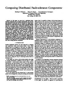
Operator Figure 1: Robo-MEDIC Robotic Fault Tolerance Hardware/Software Environment. this analysis will be embedded into the CLIPS expert system environment [6]. This NASA-developed public domain software package is commonly used by government agencies and is running on our computer systems. The resulting expert system package, Robo-MEDIC (Robot Manipulator Error Detection and Intelligent Correction) will provide diagnostic assistance to the operator and will interface with the control computer of the robot as shown in Figure 1. RoboMEDIC will be able to use the fault trees as a flow chart of failures. Nodes in the trees will have some fault tolerant action associated with them that will allow the robot to take advantage of inherent backup or alternate paths charted by the fault tree. By maneuvering around the trees, Robo-MEDIC will perform fault tolerant recovery actions as a sequence of these smaller, simpler actions.
1.3
Fault Detection Simulator and Trick
In addition to the fault tree analysis, we are examining failures and testing fault detection schemes using a simulation of a generic four link, planar robot. We will be integrating the concepts derived from the simulator into Trick [1], a robotics software testbed developed at NASA Johnson Space Center by Leslie J. Quiocho and Robert Bailey. The Trick software package already contains the information to model the seven-joint Robotic Research Arms, the Space Shuttle RMS, and the full Riceobot with base and two arms. Data modules provided by Trick allow the user to build customized robots with many different types of sensors, joints, and links. The software can currently model a joint failure by locking the joint. Our research is expanding the capabilities of the software to model runaway joints, fault detection schemes, and fault tolerance algorithms. The flexibility of the software allows the failure analysis developed in this paper to be extended to a variety of different robots.
2 2.1
Robotic Fault Tree Analysis Analysis Technique
Fault Tree Analysis (FTA) is a deductive method in which failure paths are identified by using a fault tree drawing or graphical
6
2
ROBOTIC FAULT TREE ANALYSIS
Table 1: Fault Tree Analysis Symbols
Symbol
Function
AND gate
All inputs required to produce output event.
OR
Any one input event causes the output event.
gate
Rectangle
Diamond Circle
Triangle
A malfunction which results from a combination of fault events through logic gates. A fault event for which the causes are left undeveloped. A basic fault event. This includes component failures whose frequency and failure mode are known. A suppressed tree. The tree is detailed in another figure.
representation of the flow of fault events [2]. FTA is a wellknown analysis technique often used in industry for computer control systems and large industrial plants. Each event in the tree is a component failure, an external disturbance, or a system operation. The top event is the undesired event being analyzed and, in this research, is the failure of the entire robot. The events are connected by logic symbols to create a logical tree of failures. Some of the basic symbols are explained in Table 1. The explanation of the FTA technique in [2] promotes a top down development of the fault tree. The top event is broken down into primary events that can, through some logical combination, cause the failure at the top. This process is repeated to deeper levels until a basic event or an undeveloped event is reached. Some conditions or causes may be left undeveloped if the probability that they will occur is small enough to be ignored.
2.2
Failure Propagation/Probability Analysis
Once the fault trees are built, the information available may be enhanced by a quantitative analysis of the failures. Failure rates are assigned to each input event and propagated up the tree based on the rules of the connecting logic gates. The output of an OR gate is the sum of the inputs. The resulting probability of the combined input events is greater than the probability of an individual input event. The output of an AND gate is the product of the inputs. The resulting probability of all the events occurring is thus less than the probability of any one occurring. The AND gates represent some form of redundant measurement or capability and are more desirable in the fault tree as the probability of a failure decreases through the combination of lower level events. A Markov or semi-Markov model approach to probability analysis can also be developed based on the PAWS/STEM [3] and CARE III [12] reliability analysis packages. These packages can analyze simpler fault trees as well as Markov chains, but they are not necessarily optimized to handle the simpler structures
2.3
Fault Tree Pruning
7
[10]. These analysis tools were also not designed for robotics and thus would not take advantage of some of the commonality within robot structures. We will include some of the advantageous aspects of using Markov models in our CLIPS-based expert system, Robo-MEDIC. A quantitative analysis provides a measure of the overall chance of a complete failure for each robot. The structure provided by the fault trees organizes the probabilities appropriately for the robot system and provides a simple map of how the probabilities relate to each other. Using the trees, robots of significantly different origin and structure can be compared for fault tolerant abilities and survivability. The integrated Robo-MEDIC expert system will provide diagnostic capabilities by using the fault trees and will alert the operator of an impending failure. It can be used for off-line comparisons of robots or for suggesting possible corrective actions to an operator and the low-level robot controller during real operations.
2.3
Fault Tree Pruning
A suggested drawback of FTA is that there is no way to ensure that all the causes of a failure have been evaluated [2]. The designer tends to pick out the important or most obvious events that would cause a given failure. However, the events that are not modeled normally have a low probability of occuring and can be ignored or treated as a basic event without overly biasing the analysis. Several failures may also be interconnected creating lateral branches or cycles in the fault tree. In some robots, one motion at a joint may be coupled with another motion such that failure of either motion causes the failure of the other. It is also difficult to determine the relationships between some failures. For example, the failure of all the internal feedback sensors at the elbow joint of a robot may make the robot blind to the elbow position. The elbow has not actually failed, but the robot is unable to detect the results of any commands sent to the elbow. Thus, the sensor malfunction does not contribute to an elbow failure specifically but may cause a failure of the entire robot. Relationships like these make the tree complex and difficult to understand. These problems can be overcome by working to simplify the tree. In the case of the coupled motions, the two failures can be considered as one with twice as likely a probability of occurring.
2.4
Riceobot Fault Trees
To provide a foundation for the analysis of general robots, we have chosen to analyze the arm of the Rice University Riceobot. The arm has eight degrees of freedom: three motions in the shoulder (z translation, pitch, and yaw), two motions in the elbow (roll and pitch), and three motions in the wrist (roll, pitch, and yaw). The results obtained from the Riceobot apply to most general robots especially since the Riceobot has a wide variety of commonly used link, joint, and motor arrangements. Overall Robot Failure Several fault trees have been developed and a few are reproduced in the following pages. The top event is obviously the failure of the robot (Figure 2). The primary causes of a robot failure are
8
2
ROBOTIC FAULT TREE ANALYSIS
Failure of Robot
Power Failure
Failure of Shoulder
Failure of Elbow
Failure of Wrist
Failure of Computer System
External
Failure of Gripper
Figure 2: Top Level Fault Tree for Entire Riceobot. power failure, computer system failure, or a combination of failures of the joints. If the robot is fault tolerant, it can withstand the failure of several joints. By stablizing the faulty motion or joint in some manner (such as locking the joint), it is possible that the other motions can still provide some functional capability to the robot. This ability results in the AND gate combining the joint failures in Figure 2 and decreases the probability of a failure of the robot. Joint Failures The Riceobot has two directly driven motions: the shoulder zdirection motion and the wrist roll motion (Figure 3). The fault trees for these motions are quite simple since only the failure of
Failure of Wrist
Failure of Wrist Pitch/Yaw
Failure of Motor
External
Chain/ Cable Loose
Gear-Train Failure
Chain/ Cable Snap
Link Breaks
Cable Guide Wheel Loose or Off
Jacket Unscrews
Failure of Wrist Roll
External
Failure of Motor
Connector Failure
Cable Comes Free of Clamp
Joint Link Becomes Stuck
Strip Threads
Figure 3: Sub-Level Fault Tree for Wrist System.
Failure of Universal Joint
Joint Clamp to Motor Loosens
External
Joint Breaks
2.4
Riceobot Fault Trees
9
the motor plays an important role in the failure of the motion. The other motions of the Riceobot depend on some form of geartrain assembly to allow the spatially separated motor to drive the joint. Failure of the gear-train can be caused by basic events as simple as a loosening of the chain or cable. Motor and Sensor Failures The probability of a motor failure is dependent on the type of motor used. The Riceobot contains both brushless DC and stepper motors. Each motor also has a gear box which may fail due to gear slippage or wear. A power failure affects all motors as well as any other electrically driven parts in the robot, but each motor could lose power separately if its specific power cables break. A motor failure could conceivably also be the cause of a sensor failure when sensors are mounted on the shafts of the motors. Sensors are also affected by incorrect calibration and external noise or vibrations. (See Figure 4.) Computer System Failures The computer system of the Riceobot consists of three main parts: (1) amplifiers which read from the optical encoders and drive the motors, (2) servo control chips which store information about the different motors and convert the desired angles into currents for each motor, and (3) an on-board host computer which is programmed in C and computes the desired angles for the desired motions (Figure 5). These three parts each contain at least one board filled with TTL chips, capacitors, power transistors, resistors, and other analog and digital circuit parts. A failure of any one of these parts may not cause a failure of the entire board; but if a board did fail, the robot would be unable to function. The robot cannot withstand the failure of all the servo controllers or all the amplifiers because it would no longer be able to communicate with the joints. Failure of Wrist
Failure of Wrist Pitch/Yaw
Failure of Motor
External
Chain/ Cable Loose
Gear-Train Failure
Chain/ Cable Snap
Link Breaks
Cable Guide Wheel Loose or Off
Jacket Unscrews
Failure of Wrist Roll
External
Failure of Motor
Connector Failure
Cable Comes Free of Clamp
Joint Link Becomes Stuck
Strip Threads
Figure 3: Sub-Level Fault Tree for Wrist System.
Failure of Universal Joint
Joint Clamp to Motor Loosens
External
Joint Breaks
10
2
ROBOTIC FAULT TREE ANALYSIS
Sensor Failure
Incorrect Callibration
Local Power Lines Fail
Failure of Motor
Connection to Amp Failure
Connector for Cable Strip Faulty
Lose Cable Strip
Local Power Lines Fail
Sensor Logic Board Failure
Gear Box Failure
Gears Slip
Wear on Gears
Figure 4: Sub-Level Fault Tree for Sensor System.
Detecting a non-terminal failure in the computer system requires some form of testing circuitry or the ability to poll components to see if they are still alive. The IEEE standard 1149.1 Test Access Port may be incorporated into any VLSI chip on the boards and could be used for active testing. Radiation hardened circuits [15] should also be used in the computer system. Correction code bits can be used to check data transfers and could identify a bus failure if the bits were consistently wrong.
2.5
Derived Riceobot Fault Detection
The qualitative analysis of these fault trees has proven useful in pointing out some of the limitations of the Riceobot in regards to fault detection and fault tolerance. With only one sensor at each joint, the Riceobot represents the worst case scenario for detecting sensor and joint failures. The only option available to the fault detection software is to compare the sensed angles with the calculated desired angles. After accounting for a predetermined threshold to mask any precision errors in the calculations or sensing equipment and possibly adjust for load effects, any difference between the sensed and desired values must be considered the result of a failure. The computer is, however, unable to differentiate between a sensor malfunction and an actual joint failure due, for example, to a frozen motor. The computer must therefore shut down the joint and proceed with fault tolerance schemes based on a new model of the robot with fewer possible motions. The Riceobot’s fault detection capabilities could be improved by drawing on the vision system to determine the joint angles. With the computer’s calculations and the sensor reading, this third estimate of the angle would help distinguish between a sensor failure and a real joint failure. The Riceobot would still be able to function in the presence of one sensor failure. Using the vision system for this task, however, increases the load on the image processing software and may hinder the system’s ability
Internal Motor Failure
External Damage/ Noise
11
Sensor Failure
Incorrect Callibration
Local Power Lines Fail
Failure of Motor
Connection to Amp Failure
Connector for Cable Strip Faulty
Lose Cable Strip
Local Power Lines Fail
Sensor Logic Board Failure
Gear Box Failure
Gears Slip
Wear on Gears
Figure 4: Sub-Level Fault Tree for Sensor System. to perform its normal vision tasks.
3
Robot Fault Detection
The fault trees give an idea of the interaction between failures in a system. The trees also provide a map of alternate paths for detecting faults or bypassing failures. In order to expand on this information and to show how modeling errors or other uncertainties affect fault detection, we need to simulate the robot and the fault detection algorithm. Because of the Riceobot’s lack of sensors and the complexity needed for its fault detection algorithm, we are initially simulating fault detection using a computer modeled planar, four link robot [7]. The current program will need to be expanded extensively for the Riceobot and will be accomplished by implementing the fault detection routine in the CLIPS expert system as part of Robo-MEDIC. The four link robot is essentially just four cylinders placed endto-end. All joints are rotational and move in the same plane. A simulated optical encoder and tachometer were added for each joint. The fault tree for this robot is relatively simple (Figure 6). We have not included the possibility of link breakage or global power failure in the simulation. The motors are in essence direct drive with no gear trains and fail only in a locked mode. This conditions pruned each joint subtree down from the complexity of the Riceobot trees to an easily simulated failure situation. It is interesting to note that it is the fault detection software which allows the joint to survive in the presence of a single sensor failure thus creating the AND gate under each motor failure in the tree. If both sensors at a joint fail, the host computer is blind to that joint and the fault detection routine forces a motor failure to prevent the joint from moving too far without computer supervision. Thus, the dual sensor failure subtree is a cause of the motor failure event for each joint.
Internal Motor Failure
External Damage/ Noise
12
3
ROBOT FAULT DETECTION
Failure of Computer System
Servo-Control Board Failure
Failure of Components
Sensor Failures
Host Computer Failure
Amplifier Board Failure
bonding, status indicators, sockets fail
Failure of Components
TTL chips, processors, ROM, RAM fail
soldering, chip sockets, etc, fail
transistors, capacitors, or resistors, fail
Failure of Components
Sensor Failure (1)
Figure 5: Sub-Level Fault Tree for Computer System.
3.1
Fault Detection Simulator
The structure of the simulator is shown in Figure 7. The flow of information is from the simulated host computer through the robot and then the sensors to the fault detection program and finally back to the host computer. The host computer uses the desired angles computed by a planner routine and the estimated present position of the robot derived from the sensors to calculate the torque necessary to move each link to its desired destination. The controller is a standard PD computed torque type controller. The robot routine then takes the calculated torques and determines the new position, velocity, and acceleration for each joint. The optical encoders estimate the positions by truncating the value of each angle based on each encoder’s precision. The tachometers pass the velocities through a first order filter based on a predetermined motor lag time. The sensors are modules from the Trick simulation package and represent our initial efforts at integration with Trick. These estimates of the angles and velocities are passed into the fault detection procedure which checks for failures and either passes to the host what it considers good estimates of the position, velocity, and acceleration or signals the motor of a joint with two bad sensors to shut down.
3.2
Host Computer Model
The simulated host computer uses the following dynamics equation as a model for the robot: ˙ τ = [M (θ)]θ¨ + N (θ, θ),
(1)
where τ is the joint torque vector, [M ] is the inertia matrix, and N is the Coriolis and centrifugal torque vector. The [M ] matrix and N vector are computed based on the estimated angles from the sensors. Since the robot is planar, gravity is orthogonal to
External
Sensor Failures
Sensor Failure (2)
Card Cage Failure
bonding, status indicators, etc., fail
Sensor Failure (n)
3.2
Host Computer Model
13
Failure of Computer System
Servo-Control Board Failure
Failure of Components
Sensor Failures
Host Computer Failure
Amplifier Board Failure
Failure of Components
bonding, status indicators, sockets fail
TTL chips, processors, ROM, RAM fail
soldering, chip sockets, etc, fail
transistors, capacitors, or resistors, fail
Failure of Components
Sensor Failure (1)
Figure 5: Sub-Level Fault Tree for Computer System. the plane of motion and there are no resultant gravity torques to consider. Friction is also ignored in this model. The PD controller for this model becomes:
˙ + N (θ, θ). ˙ (2) τ = [M (θ)]{θ¨d + [KP ](θd − θ) + [KD ](θ˙d − θ)}
The matrices [KP ] and [KD ] are the position and derivative gains, respectively, and are used to control tracking and steady state errors by feedback control. For critical damping, the gains become:
Failure of Robot
Failure of Joint 0
Failure of Joint 1
Failure of Joint 2
Failure of Joint 3
Failure of Motor
Failure of Motor Parts
Failure of Encoder
Failure of Tachometer
Figure 6: Four Link, Planar Robot Fault Tree
External
Sensor Failures
Sensor Failure (2)
Card Cage Failure
bonding, status indicators, etc., fail
Sensor Failure (n)
14
3 Report of Failures
Fault Detection
θe θt
θ θ θ
ROBOT FAULT DETECTION
Encoders
θr
Tachs
θr Failure Information
d d d Instigate Failures Robot fail motor signal
θθ θ Host Computer (calc torques)
Planner
τ
(calc real accelerations, velocities, and angles)
θ θ θ
d d d
Figure 7: Fault Detection Simulator Flow Chart
[KD ] = 2ω, [KP ] = ω 2 ,
(3)
where ω is the natural frequency input by the user. The natural frequency is typically set to 1 for most runs of the simulator. A higher natural frequency would increase the effects of the gains in the feedback control.
3.3
Robot Model
The simulated robot is a procedure which takes the computed torque from the simulated host computer and determines the resulting four robot angle accelerations based on the equation: ˆ ]−1 τ − [M ]−1 (N ˆ ). θ¨ = [M
(4)
ˆ ] and N ˆ are the inertia matrix and Coriolis and cenHere, [M trifugal torque vector as before but are now based on the real robot angles instead of the sensed angles. The matrices have also been injected with a small constant error to simulate the effects of a load on the robot. The joint angle, θ, and its first derivative are estimated by the equations: θ˙i = θ˙i−1 + (Δt)θ¨i ,
(5)
θi = θi−1 + (Δt)θ˙i .
(6)
If a motor failure has occurred, θ¨ and θ˙ are set to zero to simulate the effects of a locked motor. The position thus remains constant. Only the locked motor is currently simulated, but other failure modes could result in runaway motors or free-spinning motors. The robot’s position, velocity, and acceleration calculated in this procedure are sent to the sensor routines. The robot position is also sent to the graphics simulator which displays the motion on the screen. This is the same graphics program used by the Trick simulation package.
3.4
Fault Detection Capabilities
3.4 3.4.1
15
Fault Detection Capabilities Failure Modes
If a sensor breaks and the failure goes undetected, the host computer will be performing its calculations using erroneous information. In this simulator, the encoders break in a frozen mode continuously reporting the last value read before the failure. The tachometers fail by continuously reporting zero velocities and thus constant positions. With these failure modes, the host sees the error between the sensed angle and the desired angle grow for the joint with the faulty sensor, and the control equations increase the appropriate output torque to the robot to try and compensate for the error. The joint with the faulty sensor swings wildly off course because the host keeps trying harder and harder to get the broken sensor value to match the desired value. Since the calculations for all the joints are based on knowledge of where the other joints are located, all of the other output torques are also computed incorrectly and the joints all stray from their desired paths. When a motor fails, it locks in position and the joint is then unable to move. If a motor failure goes undetected, the sensors are still reading the correct information. In reality, the motor failure would probably result in a sensor failure as well, but the result would still be that both sensors are reporting a constant joint angle. The control equations try to push the broken joint closer to the desired value but the frozen motor does not respond to the torques. Since the sensors are still reporting the actual position of the joint, all the other calculations are based on correct data and the other joints can continue with their normal motions. The plan must be modified, however, to get the end effector to its desired location. 3.4.2
Thresholds
These two undetected failures reveal the importance of getting accurate sensor readings and of detecting a sensor failure quickly. A frozen motor is not as critical a failure in most cases and can be dealt with at a more leisurely pace. Since the sensors are not perfectly accurate, an acceptable threshold for the error between sensor reading and desired value must be chosen. Unfortunately, even during normal operation, the error between the actual angle and the desired angle can be relatively large especially at the beginning of a run before the controller has time to bring the error under control. Choosing the maximum error found during a failure-free run results in a threshold that is so large, it may take several time steps to notice the error from a broken sensor. By the time the failed sensor is detected, the robot controller has already been infected with the erroneous information and the robot is either off course or has damaged itself. Fortunately, the error between the angles recorded by the two sensors during normal operation is very small even after integrating the tachometer reading to get the angular position. Fortunately, modeling errors and errors induced by unpredicted loads would affect both sensors in a similar manner. A tight threshold can be chosen for a comparison of the two sensed positions. If this threshold is exceeded, the fault detection software assumes that one of the sensors has failed and appropriately chooses one as the working sensor from which to take the recorded data. The larger thresholds from the typical error between the sensed and desired angles are still monitored, however. The large thresholds
16
3
ROBOT FAULT DETECTION
provide a means of checking for a motor failure. The psuedocode for these checks is reproduced below. The angle θd and its derivatives are the desired values. The variables θt , θ˙t , and θ¨t are the values derived from the tachometer reading. The results based on the encoder are θe , θ˙e , and θ¨e . Finally, θ and its derivatives are the values sent to the robot controller. If ((encoder working) and (tachometer working)){ θ = θe , θ˙ = θ˙t , θ¨ = θ¨t If ((|θt − θe |) >= threshold){ if (encoder working){ tachometer = failed θ = θe , θ˙ = θ˙e , θ¨ = θ¨e }else{ encoder = failed θ = θt , θ˙ = θ˙t , θ¨ = θ¨t } }else{ if ((|θd − θt |) >= tachometer-threshold) tachometer = failed if ((|θd − θe |) >= encoder-threshold) encoder = failed }
} If ((tachometer == failed) and (encoder != failed)){ if ((|θd − θe |) < encoder-threshold){ θ = θe , θ˙ = θ˙e , θ¨ = θ¨e }else{ encoder = failed motor = failed send stop motor signal to robot } } If ((encoder == failed) and (tachometer != failed)){ if ((|θd − θt |) < tachometer-threshold){ θ = θt , θ˙ = θ˙t , θ¨ = θ¨t
}
}else{ tachometer = failed motor = failed send stop motor signal to robot }
Choosing which sensor has failed and which is still working when the tight tolerance is exceeded is the most difficult task. Intuitively, one would expect the sensor with a reading closer to the desired value to be the working sensor and would switch to obtaining all the information from that sensor. However, experience has shown that the fault detection software choses the correct sensor only when the desired values are increasing. If the desired angles are decreasing in value, it consistently picks the failed sensor as the working one. This problem is a result of the time it takes the controller to bring the errors under control and the failure modes for the sensors. Both the encoders and the tachometers fail by reporting a constant angular position either directly or by integration of a zero velocity. First, let us assume the sensors always read less than the desired value. If a sensor fails and gets stuck at a specific value while the desired values are increasing, the error will
3.4
Fault Detection Capabilities
17
Table 2: Sensor Failure Detection Tests Ordering θd < θt , θe θt , θe < θd θt < θd < θe θe < θd < θt
Encoder Fails largest error (2) smallest error (1,2) largest error smallest error (1,2)
Tachometer Fails largest error (2) smallest error (1,2) smallest error (1,2) largest error
grow and the fault detection routine should take the angle information from the sensor that reads closer to the desired value. However, if the sensor fails while the desired values are decreasing, the desired values are approaching the failed value. The error starts decreasing and the surviving sensor is often the one whose absolute error is larger. (See Table 2 for listing of results.) The opposite relationships hold if both sensors are reading values greater than the desired angle. A failed sensor would then have the smaller error during an increase in desired angles and the larger error during a decrease in desired angles. The various sensor failure situations that arise in the presence of increasing desired values and the relative size of the error for the surviving sensor are listed in Table 2. The cases in which the initial, naive algorithm is successful in choosing the survivor are marked with an “1”, and the cases in which the second algorithm is successful are marked with a “2”. The table represents half of the possible cases. The table for decreasing desired values would look similar with the equivalent number of successes for each algorithm as in Table 2. By checking whether the desired values are increasing or decreasing and performing the appropriate comparisons to choose the surviving sensor, the algorithm’s success rate for the cases listed in the table increases from 50% to 75%. The algorithm still has a problem with the cases where the sensors are reading on opposite sides of the desired value. The fault detection program picks a failed tachometer as the survivor if the tachometer value is trailing a trend of decreasing desired values while the encoder is preceding the desired values. Similarly, the fault detection program should pick a failed encoder as the surviving sensor during a trend of increasing desired values if the encoder value is preceding the desired value by a large enough margin while the tachometer is trailing the desired value. We were unable to demonstrate this second error as the encoder value was close enough to the desired value that when the encoder failed, the desired value passed the failed value in the next time step. The fault detection scheme was able to guess correctly in this situation. In general, our simple fault detection simulator is capable of detecting for each joint a single sensor failure, a single sensor failure followed by a motor failure, or a motor failure. The simulator will eventually detect a second sensor failure and will catch the single failures it has missed, but it has allowed enough erroneous sensor readings through to the controller that other joints have been knocked off course and fail as well. In order to improve the fault detection algorithm, we must switch from the hard-coded voting scheme presented above to other forms of analytical re-
18
4 CONCLUSIONS AND FUTURE WORK
dundancy which use filters [14, 11], adaptive thresholds [8], or parity relations [5]. Willsky [14, 5] gives a good overview of the various methods of analytical redundancy. Most of the work in this area has been focused on failure detection in aircraft, power generation system and other mechanical systems. Unfortunately, the amount of uncertainty and modeling errors present in most robotic control systems makes several of these methods inaccurate. The generation of residuals using parity relations is one example of a method which would be unsuitable for robotic applications. [8].
4
Conclusions and Future Work
In this paper we have presented new results in fault tree analysis and fault detection for robot manipulators. This research sets the stage for significantly enhanced activity in fault tolerance for robotics. Once a failure can be detected and isolated, a fault tolerant expert system like Robo-MEDIC can proceed with the appropriate actions to make use of the existing robot structure, redundancy, and alternate paths. There already exist a variety of computer fault tolerance schemes which can provide a starting point for creating these structurally independent robotic fault tolerance algorithms. The fault tree analysis for the Riceobot has proven useful in pointing out some trouble spots for fault detection and fault tolerance. Even without a quantitative analysis, the importance of certain components and the severity of different failures are revealed in the fault trees. For robots, the good health of the internal sensors is shown to be extremely desirable. Erroneous data from even one sensor at a joint can cause the whole robot to deviate drastically from its course if the failure is not detected quickly. Without the sensors, the robot also loses much of its capability to detect faults. Developing methods for early detection of sensor malfunctions thus has a high priority in this research. By simulating relatively simple fault detection situations, we are gaining a better understanding of how to satisfy this need for early detection. Our simulator has shown that to avoid false alarms due to modeling errors and noise we must implement large thresholds which let some failures go undetected for too long. Other relationships must be developed concerning the information available in order to improve the fault detection algorithms. Once these schemes have been perfected, we will be able to embed the algorithms in an expert system and integrate the simulation into the Trick simulation package to create a more flexible fault detection and fault tolerance simulator. The analysis of the fault trees in this paper will be useful in creating fault tolerant algorithms. Through an analysis of the structures, fault tolerance schemes must be developed which will attempt to maintain the health of the internal nodes in the presence of failures in their children. Detection schemes and fault tolerant algorithms will be tested on the Trick robotic software testbed.
Acknowledgments This work was supported in part by the National Science Foundation under grants MIP-8909498 and MSS-9024391 and in part
REFERENCES
19
by a Mitre Corporation Graduate Fellowship and an NSF Graduate Fellowship.
References 1. Bailey, R. W. and Quiocho, L. J., Trick Simulation Environment Developer’s Guide, NASA JSC Automation and Robotics Division, Houston, TX, Beta-release edition, February 1991. 2. Bloch, H. P. and Geitner, F. K., An Introduction to Machinery Reliability Assessment, Van Nostrand Reinhold, New York, NY, 1990. 3. Butler, R. W. and Stevenson, P. H., “The PAWS and STEM Reliability Analysis Programs,” NASA Technical Memorandum 100572, NASA Langley Research Center, Hampton, VA, March 1988. 4. Chean, M. and Fortes, J. A., “A Taxonomy of Reconfiguration Techniques for Fault-Tolerant Processor Arrays,” IEEE Computer, 23(1):55–67, January 1990. 5. Chow, E. Y. and Willsky, A. S., “Analytical Redundancy and the Design of Robust Failure Detection Systems,” IEEE Transactions on Automatic Control, AC29(7):603–614, July 1984. 6. Giarratano, J. and Riley, G., Expert Systems: Principles and Programming, PWS-Kent Publishing Co., Boston, MA, 1989. 7. Hamilton, D. L., “A Simulation of Robot Motion Control,” Advisors: I. D. Walker and J. K. Bennett, Rice University, Department of Electrical and Computer Engineering, Houston, Texas, April 1991. 8. Horak, D. T., “Failure Detection in Dynamic Systems with Modeling Errors,” AIAA Journal of Guidance, Control, and Dynamics, 11(6):508–516, NovemberDecember 1988. 9. Maciejewski, A. A., “Fault Tolerant Properties of Kinematically Redundant Manipulators,” In 1990 IEEE Conference on Robotics and Automation, pages 638–642, Cincinnati, OH, May 1990. 10. Martensen, A. L. and Butler, R. W., “The Fault-Tree Compiler,” NASA Technical Memorandum 89098, NASA Langley Research Center, Hampton, VA, January 1987. 11. Merrill, W. C., DeLaat, J. C., and Bruton, W. M., “Advanced Detection, Isolation, and Accommodation of Sensor Failures - Real-Time Evaluation,” Journal of Guidance, Control, and Dynamics, 11(6):517–526, NovemberDecember 1988. 12. Stiffler, J. J. and Bryant, L. A., “CARE III Phase II Report - Mathematical Description,” NASA Contractor Report 3566, NASA Langley Research Center, Hampton, VA, 1982. 13. Tesar, D., Sreevijayan, D., and Price, C., “Four-Level Fault Tolerance in Manipulator Design for Space Operations,” In NASA First International Symposium on Measurement and Control in Robotics, volume 3, page J3.2.1, Houston, TX, June 1990. 14. Willsky, A. S., “A Survey of Design Methods for Failure Detection in Dynamic Systems,” Automatica, 12:601–611, 1976. 15. Winokur, P. S., “Radiation-Hardened Circuits for Robotics,” Proc. Fourth Topical Meeting on
20
REFERENCES
Robotics and Remote Systems, pages 311–315, February 1991. 16. Wu, E., Diftler, M., Hwang, J., and Chladek, J., “A Fault Tolerant Joint Drive Systems for the Space Shuttle Remote Manipulator System,” In 1991 IEEE International Conference on Robotics and Automation, pages 2504–2509, Sacremento, CA, April 1991.