the spectral re-growth caused by a strong adjacent channel. Significant reduction in ... channel wireless data transmission over multi-mode fibre for WLAN without ... interfering with a weak channel and hence limiting the system performance.
Feed-Forward Linearised Uncooled DFB Laser in a Multi-Channel Broadband Wireless over Fibre Transmission at 5.8 GHz T. Ismail, C. P. Liu, J. E. Mitchell, and A. J. Seeds Department of Electronic and Electrical Engineering, University College London, Torrington Place, London, WC1E 7JE, United Kingdom Abstract — We present the first experimental demonstration of a feed-forward linearised uncooled laser at 5.8 GHz in a wireless-over-fibre system for the transmission of multi-channel broadband 16 QAM and 64 QAM signals over 2.2 km of single mode fibre intended for wireless LAN applications. We demonstrate that with such a linearisation scheme, a reduction of 20 dB is achieved in the spectral re-growth caused by a strong adjacent channel. Significant reduction in the error vector magnitude and improved constellation and eye-diagrams were observed. Intermodulation distortion is reduced by 13 dB when two strong channels are at +10 dBm input level. Index Terms — Feed-Forward systems, Intermodulation distortion, Optical communication, Radio-over-Fibre, Uncooled laser.
I. INTRODUCTION The demand for broadband services such as wireless local area network (WLAN) using the IEEE802.11a/b/g standards is showing rapid growth. The Industrial Scientific Medical (ISM) band at 2.4 GHz is used for the IEEE802.11b/g and the 5 GHz band is used for the IEEE802.11a standard. Interest is also growing in the deployment of fixed wireless access (FWA) systems such as Worldwide Interoperability for Microwave Access, (WiMAX IEEE802.16) in the 5.8 GHz band [1]. It is anticipated that future mobile networks will use microwave frequencies as the access medium (15-60 GHz), as these offer a large bandwidth for data transfer [2]. At these frequencies, transmission of signals using optical fibre is preferred because of the higher loss associated with coaxial cables. It has been shown that optical fibre is preferred over coaxial cable for remoting distances of more than 100m for cellular applications [3]. Wireless-over-fibre is a suitable technology for the realisation of high capacity future broadband wireless access networks allowing a significant reduction in the complexity and cost of the remote Base Stations (BSs). It also provides an inexpensive method for system upgrade, since most of the signal processing functions are done at the Central Station (CS) and not at every BS. The technology has already been commercialised for cellular communication systems using 1-2 GHz band to improve radio coverage [4]. To provide network coverage such as at an airport, radio frequency (RF) modulated optical signals are generated at the CS and distributed to remote BSs without significant loss using optical fibre and reach
the mobile users via RF transmission allowing mobility. For a simple and low cost solution, direct modulation of uncooled lasers is preferred. This allows the temperature control circuit to be eliminated leading to a lower power, more compact and a cost effective solution. Previously, Niho et al [5] have developed a 5 GHz radio-on-fibre link for wireless systems and characterised the link performance. Hartmann et al [6] have reported a single channel wireless data transmission over multi-mode fibre for WLAN without feed-forward linearisation. However, in a multi-channel system since the BS can simultaneously receive high and low power signals, depending on how far the users are from the BS, any non-linearity in the optical link, such as non-linear distortion introduced by a directly modulated laser, can cause spectral re-growth from a strong input signal, interfering with a weak channel and hence limiting the system performance. Previously we reported a feedforward linearisation system which substantially enhanced the spurious free dynamic range [7]. In this paper, we present the first experimental demonstration centered around 5.8 GHz for the transmission of multichannel broadband 11 MSymb/s, 16 QAM and 64 QAM wireless channels over 2.2 km single mode fibre (SMF). We use a directly modulated uncooled DFB laser with feed-forward linearisation to improve laser non-linear performance in a multi-channel system. The spectral regrowth of the strong channel has been reduced by 20 dB with feed-forward linearisation, allowing the weak neighbouring channel to be easily recovered and demodulated. The use of this linearisation technique has resulted in improved system performance and error vector magnitude (EVM) for 16 QAM and 64 QAM signals. II. EXPERIMENTAL ARRANGEMENT The performance of an optical transmission system depends greatly on the non-linearity of the laser diode. Any non-linear distortion generated by the laser can cause spectral re-growth affecting the adjacent channels. Therefore, some form of distortion compensation is necessary. Pre-distortion techniques have been used to compensate laser diode non-linearity for Cable TV [8, 9] and for multi-service wireless-over-fibre systems covering cellular bands [10]. However, the main
disadvantage with pre-distortion is the complexity of the electrical circuit to be designed and the difficulty of optimising suppression of the various harmonic and intermodulation distortion (IMD) products at the same time. Dual parallel modulation techniques where the undesired IMD signal is cancelled by that of the other DFB laser diode with π phase difference have been demonstrated to reduce third order IMD at 2.2 GHz for narrow band operation, but the fifth order IMD signals are not fully compensated. In contrast, the feed-forward technique is more effective since it can suppress all IMD and harmonic distortion products over a wider bandwidth.
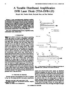
Ch A, 5.765 GHz Fixed +12 dBm R&S SMU200A Vector Signal Generator Ch B, 5.785 GHz Power varied PRBS 23, 11 MSymb/s
Optical Feed-forward Transmitter Microwave Laser 1 splitter
Fibre delay
PIN diode
Optical Coupler
Laser 2 Variable gain amplifier
Variable gain amplifier
180° hybrid coupler
Electrical delay
+
2.2 km SMF
−
Electrical delay
R&S FSQ26 Vector Signal Analyser Tuned to Ch B, 5.785 GHz 50 dB gain RF amplifier
PIN diode 0.83 A/W (DC)
Fig. 1. Experimental arrangement with feed-forward linearisation
Figure 1 shows the experimental implementation of the feed-forward system, employed to linearise the optical intensity output of a commercially available fibre pigtailed DFB Laser 1. The basic operation of the feedforward circuit is that the input signal is split into two paths; one path modulates the primary laser while the other path is used as a reference signal. Detecting the signal from Laser 1 and comparing it with the time delayed reference path provides an error signal at the output of the 180-degree hybrid coupler which is then amplified and modulates the secondary laser. The modulated optical signal from Laser 2 is combined with the optical signal of Laser 1 to cancel the distortion products when detected by the PIN photodiode. The detailed working principle of the feed-forward linearisation has been previously reported [7]. For maximum cancellation of the distortion products amplitude and phase matching is required both for the carrier suppression loop and the distortion cancellation loop. This is facilitated with the use of variable gain amplifiers and microwave phase shifters. Two Rhode & Schwarz SMU200A Vector Signal Generators (VSGs) are used to provide two channels, A and B, at 5.765 GHz and 5.785 GHz respectively and were internally filtered with a root raised cosine function
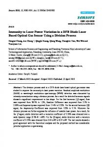
III. EXPERIMENTAL RESULTS To illustrate the effectiveness of the feed-forward linearisation in suppressing spectral re-growth from a strong input (Channel A) caused by the non-linearity of Laser 1, the RF spectra of the two 11 MSymb/s, 16 QAM channels were measured with the feed-forward disabled and enabled and are shown in Figure 2 and Figure 3 respectively. -20
Detected RF Power (dBm)
R&S SMU200A Vector Signal Generator
having a roll off factor of 0.5 to reduce the occupied bandwidth. The frequencies of the two Channels A and B follow the IEEE 802.11a standard channel allocation [11] and were combined in the microwave combiner and fed to the optical feed-forward transmitter for direct modulation. The output power from the VSG for channel A was fixed at +12 dBm and Channel B input power was set to -23 dBm. The aim of the experiment was to consider the situation where the received power from a nearby user to the BS would generate a strong signal and to investigate how the spectral re-growth caused by this strong signal from Channel A would interfere with the weak neighbouring Channel B which was far from the BS. The output from the optical feed-forward transmitter was transported over 2.2 km of SMF. The feed-forward could easily be enabled or disabled by simply connecting or disconnecting Laser 2 output from the optical coupler. The linearised modulated signal at the output of the photodiode was amplified and detected using an Rhode & Schwarz FSQ26 Vector Signal Analyser (VSA).
Channel A -30 +12 dBm input
Spectral Re-growth from Channel A
-40 Channel B -23 dBm input
-50 -60 -70 -80
Resolution Bandwidth=100 kHz
5.730 5.745 5.760 5.775 5.790 5.805 5.820 Frequency (GHz)
Fig. 2.
Detected RF spectrum without feed-forward
When the feed-forward was disabled, the non-linearity generated from Laser 1 caused significant spectral regrowth from Channel A to interfere with the frequency band of the neighbouring Channel B. When the feedforward was enabled the non-linearity was compensated
The EVM for Channel B was measured in the presence of Channel A, with input power fixed at +12 dBm. With the feed-forward enabled the EVM improved
-20
Detected RF Power (dBm)
Channel A -30 +12 dBm input
1.2
-40
900m 600m
Channel B -23 dBm input
-50
S
300m 0
SWP -300m
1 of
1
-600m -900m
-60
-1.2 -1 sym
Symbols
0.2 sym/
1 sym
1 U
-70 Resolution Bandwidth=100 kHz
-80
S
SWP
1 of
1
5.730 5.745 5.760 5.775 5.790 5.805 5.820 Frequency (GHz) -1 U
Fig. 3.
Detected RF spectrum with feed-forward
and the spectral re-growth was suppressed by 20 dB allowing the spectrum of Channel B to be clearly seen. A number of measurements were conducted using 16 QAM and 64 QAM. The eye-diagrams, constellation and EVM were measured using the VSA set to Channel B at a centre frequency of 5.785 GHz with a 20 MHz channel filter bandwidth and are shown in Figure 4 to Figure 7 with and without feed-forward. The EVM is the difference between the measured symbol and the ideal reference symbol. Without feed-forward the quality of the measured eye-diagrams, constellation diagrams and EVM of the weaker channel B were severely affected by Channel A spectral re-growth. With feed-forward enabled, the eye-diagrams had wider opening and well defined constellations can be observed. The modulated symbol rate from the VSG is 11 MSymb/s. Since each 16 QAM symbol carries the information of 4 bits, the transmitted data rate is 44 Mb/s and with 64 QAM (6 bits) a data rate of 66 Mb/s is transmitted.
Fig. 5. Detected Channel B eye and constellation diagrams for 16 QAM with feed-forward. EVM is 9.3%
1.2 900m 600m 300m 0
SWP -300m
1 of
1
1 of
1
-600m -900m -1.2 1 U
SWP
-1 U
Fig. 6. Detected Channel B eye and constellation diagrams for 64 QAM without feed-forward. EVM is 19.8%
1.2
1.2
900m
900m
600m
600m
300m
300m
0
0
SWP -300m
1 of
SWP -300m
1
-600m
-600m
-900m
-900m
-1.2
-1.2
-1 sym
-1 sym
Symbols
0.2 sym/
1 sym
1 of
1
Symbols
0.2 sym/
1 sym
1 U
1 U
S
SWP
1 of
SWP
1
-1 U
Fig. 4. Detected Channel B eye and constellation diagrams for 16 QAM without feed-forward. EVM is 24.9%
1 of
1
-1 U
Fig. 7. Detected Channel B eye and constellation diagrams for 64 QAM with feed-forward. EVM is 5.2%
from 24.9% to 9.3% for the 16 QAM and 19.8% to 5.2% for the 64 QAM signals. Finally the input powers of both Channel A and Channel B with 16 QAM signals were set equal at +10 dBm and the measured RF spectra are shown in Figure 8. It can be seen that with the feed-forward disabled, there was strong IMD caused by the two high power input signals modulating Laser 1 and any low power signals in adjacent channel frequency bands would have been severely degraded. With feed-forward enabled, the IMD was suppressed by 13 dB. Although the feedforward is able to provide a greater suppression for the IMD, this was limited by the available power of the signal source as can be seen in Figure 8. The output of the generator for Channel B has some residual distortion and this cannot be compensated with the feed-forward. From Figure 8 it can be observed that the feed-forward provides at least 10 dB suppression of third order IMD from 5.735 GHz to 5.810 GHz.
Detected RF Power (dBm)
-20
Channel A & B at +10 dBm input
-30 -40
Distortion from the source
-50 Without Feed-forward -60 -70 -80
With Feed-forward
RB=100 kHz
5.730 5.745 5.760 5.775 5.790 5.805 5.820 Frequency (GHz)
Fig. 8. Detected RF spectra with feed-forward disabled (upper) and enabled (lower), both Channels A and B set at +10dBm.
VII. CONCLUSION In this paper we have demonstrated the use of feedforward linearisation at 5.8 GHz to compensate laser non-linear distortion in a multi-channel wireless-overfibre system intended for WLAN applications and fixed wireless access systems such as WiMAX. We have used two channels, each with 11 MSymb/s of 16 QAM signal and have seen 20 dB reductions in the spectral re-growth caused by a strong input channel at +12 dBm. Successful transmission was achieved with feed-forward as evident from clear and well defined constellations and improved eye-diagrams. An improvement of 15% for the 16 QAM and 14% for the 64 QAM in EVM has been observed with the use of feed-forward. Laser non-linearity becomes more severe with two strong input channels
leading to inter-channel distortion which can completely mask a third adjacent channel. A reduction of 13 dB in IMD was achieved with the feed-forward compensation. The results suggest that compensating the laser nonlinearity using the feed-forward linearisation technique improves the system performance and allows successful transmission of multiple channels in wireless-over-fibre applications. ACKNOWLEDGEMENT Aspects of this work were carried out within the FP6IST-GANDALF project (507781), funded by the European Commission. REFERENCES [1] J. E. Mitchell, “Performance of OFDM at 5.8 GHz using radio over fibre link,” Electron. Lett., vol. 40, pp. 1353-1354, October 2004. [2] A. Kaszubowska, A. Anandarajah and L. P. Barry, “Improved performance of a hybrid radio/fibre system using a directly modulated laser transmitter with external injection,” IEEE Photon. Technol. Lett., vol. 14, no. 2, pp. 233-235, Feb 2002. [3] S. Hunziker and W. Baechtold, “Cellular remote antenna feeding: fibre or coaxial cable?,” Electron. Lett., vol. 11, pp. 1038-1040, 1998. [4] Ebine. Y, “Development of fibre-radio systems for cellular mobile communications,” International Tropical Meeting on Microwave Photonics (MWP) 1999, F10.1, November 1999. [5] T. Niiho, H. Sasai, K. Masuda and S. Morikura, “Radio-on-Fibre link using direct modulation in 5 GHz band,” International Tropical Meeting on Microwave Photonics (MWP) 2002, W3-2, pp. 2528, November 2002. [6] P. Hartmann, X. Qian, R. V. Penty, I. H. White, “Broadband multimode fibre (MMF) based IEEE 802.11 a/b/g WLAN distribution system,” International Tropical Meeting on Microwave Photonics (MWP) 2004, TA-5, pp. 1763-176, October 2004. [7] T. Ismail, C. P. Liu and A. J. Seeds, “Uncooled directly modulated high dynamic range source for IEEE802.11a wireless over fibre LAN applications,” Proc of Optical Fibre Communications, (OFC 2004)., Los Angeles, California, 2004. [8] H. Lin, Y. Kao, “Nonlinear distortions and compensations of DFB laser diode in AM-VSB lightwave CATV applications,” IEEE J. Lightwave Technol., vol. 14, pp. 2567-2574, 1996. [9] H. Lin, Y. Kao, “A predistortion technique for DFB laser diodes in lightwave CATV transmission,” IEICE Trans. of Comms., vol. E79-B, no. 11, pp. 1671-1676, November 1996. [10] L. Roselli, V. Borgioni, F. Zepparelli, F. Ambrosi, M. Comez, P. Faccin and A. Casini, “Analog laser predistortion for multiservice radio over fibre systems,” IEEE J. Lightwave Technol., vol. 21, no. 5, pp. 1211-1223, May 2003. [11] IEEE Std. 802.11a-1999, New York, IEEE, 2000.