Data (SIMD) vector instructions), as well as the amount of supported ..... data parallelism with SIMD instructions. ... Extensions (AVX) and AVX2 vector intrinsics.
FEVES: Framework for Efficient Parallel Video Encoding on Heterogeneous Systems Aleksandar Ilic, Svetislav Momcilovic, Nuno Roma and Leonel Sousa INESC-ID/IST, Universidade de Lisboa Lisbon, Portugal Email: {Aleksandar.Ilic, Svetislav.Momcilovic, Nuno.Roma, Leonel.Sousa}@inesc-id.pt
Abstract—Lead by high performance computing potential of modern heterogeneous desktop systems and predominance of video content in general applications, we propose herein an autonomous unified video encoding framework for hybrid multi-core CPU and multi-GPU platforms. To fully exploit the capabilities of these platforms, the proposed framework integrates simultaneous execution control, automatic data access management, and adaptive scheduling and load balancing strategies to deal with the overall complexity of the video encoding procedure. These strategies consider the collaborative inter-loop encoding as a unified optimization problem to efficiently exploit several levels of concurrency between computation and communication. To support a wide range of CPU and GPU architectures, a specific encoding library is developed with highly optimized algorithms for all interloop modules. The obtained experimental results show that the proposed framework allows achieving a real-time encoding of full high-definition sequences in the state-of-the-art CPU+GPU systems, by outperforming individual GPU and quad-core CPU executions for more than 2 and 5 times, respectively. Keywords-Video Coding, Heterogeneous Systems, GPGPU, Load Balancing.
I. I NTRODUCTION In the past decade, a remarkable increase in the processing capabilities of commodity desktop and servers systems can be evidenced. Current off-the-shelf systems do not only rely on multi-core Central Processing Units (CPUs) to perform general-purpose computations, but also employ different accelerators and co-processors. Recently, Graphics Processing Units (GPUs) emerged as one of the most widely employed co-processors to the CPU, due to the possibility of extending their use beyond the traditional graphics purposes. Exploiting the full potential of CPU+GPU systems is not a trivial task, since the complexity of both the overall system/devices and target applications must be explicitly considered. Firstly, for each device architecture, independent parallel algorithms must be developed and optimized by relying on different programming models and tools. Secondly, these implementations need to be integrated in a unified execution environment in order to simultaneously perform computations of a single application. Additionally, autonomous and adaptive scheduling mechanisms must also be incorporated in order to guarantee the efficient use of
all employed devices, inter-device communication links and other system resources in CPU+GPU systems. On the other hand, attaining the maximum system performance is also limited by specific characteristics and complexity of the target applications. For example, data-parallel applications are usually better suited for GPU architectures, while coarser-grained parallelism is often better exploited on multi-core CPUs. However, real-world applications usually consist of several different execution modules with diverse characteristics. During the execution, the inherent inter-module data-dependencies often impose their complex interaction, e.g., when the output of one module is the input for another and/or when several modules simultaneously access a single data buffer. Hence, for efficient collaborative execution in heterogeneous systems, the unified environment needs to consider both application- and architecture-specific characteristics. Since it is generally impossible to consider a full range of characteristics, inter-module interactions and execution scenarios for general applications, a highly practical approach is herein proposed that focuses on a video encoding procedure to describe the application complexity. Due to a clear dominance of video contents in the Internet traffic [1] and growing demands for higher video resolutions, efficient video compression is essential to reduce the network bandwidth and data storage requirements. The newest video coding standards, such as H.264/AVC [2] and HEVC/H.265 [3], provide advanced coding methods to achieve higher compression rates, while retaining the video quality. However, this compression efficiency is payed by a dramatic increase in computing complexity, e.g., realtime encoding is hardly achievable on any individual device in current desktops. In the encoding procedure, a set of different processing modules is iteratively applied on each video frame to reduce the spatial, temporal and statistical redundancy in video information. The overall encoding complexity involves several data-dependency levels, namely: i) within a single module (spatial dependences within a frame); ii) across several modules (single-frame encoding); and iii) between different frames (temporal dependences). In order to cope with such application complexity, we propose herein a robust FEVES framework for inter-loop video encoding that employs adaptive scheduling and load bal-
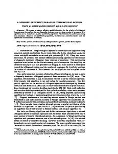
II. BACKGROUND AND R ELATED WORK According to the H.264/AVC standard [2], the Current Frame (CF) is divided in multiple 16×16 (pixels) Macroblocks (MBs), which are encoded using either an intra- or an inter-prediction mode, as presented in Fig. 1. The most computationally demanding and frequently applied interprediction mode starts with the Motion Estimation (ME) module, where the best matching candidate for the currently processed MB is found within the predefined search areas (SAs) in previously encoded RFs. In order to better suit to different shapes of moving objects, this standard allows further MB subdivisions according to 7 partitioning modes, i.e., 16×16, 16×8, 8×16, 8×8, 8×4, 4×8 and 4×4 pixels. The best matching candidate for each MB-partition is selected as the one with the minimum distortion value. It is computed according to the Sum of Absolute Difference (SAD) between all pixels from the current MB-partition and the examined candidates in the SA. The output of the ME are the offsets to the best matching candidates, i.e., motion vectors (MVs). To refine the ME, the RFs are interpolated by applying 6tap and linear filters in the Interpolation (INT). The output of the INT is stored in a Sub-pixel interpolated Frame (SF) structure, which size is as large as 16 RFs. By relying on the MVs from the ME and the SFs from the INT, the Sub-Pixel Motion Estimation (SME) is applied to further refine the MVs and provide a better prediction for each MB-partition.
MB
R* Modules intra
predicted MB
residual
inter
Motion Compensation (MC)
Transform & Quantization (TQ)
motion vectors
Motion Estimation (ME)
Sub-pixel Motion Estimation (SME)
Dequantization & Inverse Transform (TQ-1)
Entropy Coding
Current Frame (CF)
Intra Prediction
ancing techniques to challenge real-time encoding of High Definition (HD) sequences on multi-core CPU and multiGPU platforms. To exploit the computing power of these platforms, different parallelization strategies were applied to each inter-loop module and for each device architecture. Besides integration of the parallelized modules, the proposed framework also allows simultaneous execution control, automatic data access management, and cross-device workload distribution for different inter-loop modules. To the best of our knowledge, this is one of the first papers that thoroughly investigates efficient scheduling and load balancing methods for inter-loop video encoding on multi-core CPU and multiGPU systems as a unified optimization problem. The contributions of this paper are summarized as follows: • unified video encoding framework with automatic data access management for efficient orchestration of the inter-loop procedure in heterogeneous systems; • scheduling and load balancing based on linear programming and realistic performance parametrization, which explicitly considers the complexity of the video encoding modules and the overall inter-loop procedure, as well as the complexity of the heterogeneous platform; • highly optimized parallel video encoding modules for different generations of multi-core CPUs and GPUs; • real-time H.264/AVC inter-loop encoding of full HD sequences (>25fps) with Full-Search Block-Matching (FSBM) algorithm and 4 Reference Frames (RFs).
interpolated frame
Reference Frames (RFs)
Figure 1.
Interpolation (INT)
Deblocking Filtering (DBL)
reference macro-block (MB)
Block diagram of the H.264/AVC encoder: inter-loop.
In total, the ME, INT and SME modules take about 90% of the video encoding time, both on CPU and GPU [4]. According to the adopted distortion metric and the refined MVs from the SME, the best MB-partitioning mode is selected for each MB in the Motion Compensation (MC). For the selected mode, the prediction of each MB is computed by subtracting the best matching SF candidates from the original MB to obtain the prediction residual. Transform and Quantization (TQ) is then applied to the residual, which is entropy coded and sent to the decoder. Inverse Transform and Dequantization (TQ−1 ) is then applied to the quantized coefficients, to reconstruct the residual and reference MBs in the RFs, which are used in subsequent ME procedures. Finally, to remove the blocking artifacts in the RF, the Deblocking Filtering (DBL) is applied on the MBs and MB-partitioning edges. Due to their lower share in the overall inter-loop video encoding [4], MC, TQ, TQ−1 and DBL are herein referred as R* modules. In CPU+GPU systems, current state-of-the-art approaches rarely tackle the efficient parallelization of the complete encoder (or its main functional parts). They usually i) offload one inter-loop module (mainly ME) to the GPU, while the rest of the encoder is performed on the CPU [5], [6], or ii) exploit single-module CPU+GPU processing [7]. However, these approaches offer a limited scalability since only one GPU device can be efficiently employed. Several works also consider the video encoding in homogeneous multi-GPU environments [8], where CPUs are not used for computing and an equidistant partitioning of CF/RFs is applied. Our recent contributions in the area of collaborative inter-loop video encoding consider synchronous load balancing for individual modules, while focusing on the Rate-Distortion (RD) performance and CPU/GPU parallelization [9]. The work presented herein greatly advances these contributions, by proposing a unified video encoding framework that integrates: i) multi-level load balancing that considers the complexity of the entire inter-loop; ii) communication minimization and automatic data management in CPU+GPU systems; and iii) adaptive execution methods that explicitly consider the characteristics of heterogenous platform.
UNIFIED FRAMEWORK Load Balancing
Algorithm 1 Framework Control (main functionality) Performance Characterization
FRAMEWORK CONTROL Video Coding Manager Parallel Modules (CPU, GPU, …)
Data Access Management
Heterogeneous Devices
Unified collaborative video encoding framework.
CPU
CONTROL CORE p 1
...
CORE pk
CACHE
Main Memory
Figure 3.
INTERCONNECTION BUSES
Figure 2.
DRAM
DEV #W (pk+w) GPU #2 (pk+2) GPU #1 (pk+1)
D R DA RM A M
Heterogeneous CPU and multi-GPU/accelerator system.
III. FEVES: F RAMEWORK FOR I NTER - LOOP V IDEO E NCODING ON H YBRID CPU+GPU S YSTEMS In order to exploit the computational power of heterogeneous multi-core CPU and multi-GPU systems for collaborative inter-loop video encoding, a unified FEVES execution framework is proposed herein that integrates several functional blocks (see Fig. 2). The key functionality is supported on the Framework control that interacts with all other main functional blocks, i.e., Video Coding Manager, Load Balancing and Performance Characterization. The Video Coding Manager is responsible for orchestrating the cross-device collaborative execution, by invoking the respective implementations of Parallel Modules on the available devices and for automatic Data Access Management between the system main memory (DRAM) and local device memories. The collaborative execution is conducted by relying on the workload distributions provided by the Load Balancing block, which is tightly coupled with an on-the-fly system and device Performance Characterization. A. Framework Control As presented in Algorithm 1, the Framework Control functionality considers two main phases, namely: i) the initialization phase, invoked when encoding the first interframe (lines 1-6); and ii) the iterative phase, applied during the processing of each subsequent inter-frame (lines 7-11). In the initialization phase, the Framework Control firstly detects the available heterogeneous devices in the platform (line 1). It also determines device-specific capabilities (e.g., support for different types of Single Instruction Multiple Data (SIMD) vector instructions), as well as the amount of supported concurrency between the kernel invocations and data transfers for each accelerator (i.e., GPU). According to this information, the Framework Control instantiates the
1: detect the number, type and characteristics of available devices 2: instantiate appropriate Parallel Modules implementations and configure Video Coding Manager and Data Access Management 3: call Load Balancing to determine initial equidistant partitioning for ME, INT and SME modules across all pi devices 4: invoke parallel execution and automatic transfers via Video Coding Manager and Data Access Management 5: record the execution and input/output data transfer times for each assigned load on pi device, as well as for remaining R* modules 6: perform intial Performance Characterization, by calculating perdevice/module speeds and the asymmetric bandwidth of the interconnections for each non-CPU device 7: for f rame nr=2 to nr of inter f rames do 8: call Load Balancing to determine the load distribution(s) based on Performance Characterization 9: invoke Video Coding Manager, Data Access Management and Parallel Modules to simultaneously process the assigned MB rows for computationally intensive modules on each pi device, as well as to process R* modules on the best processing device 10: record the corresponding times for computations and input/output transfers and update Performance Characterization 11: end for
respective architecture-specific implementations of Parallel Modules for each device, which are used during the collaborative encoding via the Video Coding Manager (line 2). As presented in Fig. 3, current CPU+GPU platforms incorporate a set of nc CPU cores and nw GPU accelerators, i.e., pi processing devices, where i={1, . . ., nc +nw }. In current desktop/server platforms, the accelerators are usually not stand-alone processing devices. Instead, they perform the computations on data fetched from the DRAM, while the CPU is responsible for initiating both on-device executions and data-transfers across the interconnection buses. Depending on the number of available communication engines, different GPU architectures support different amounts of concurrency between computation and communication. For devices with a single copy engine, it is possible to overlap kernel executions with data transfers in a single direction (from CPU host to GPU device or vice versa). For devices with dual copy engine, it is also possible to overlap the transfers in different directions. Identification of these properties is not only crucial for proposed communicationaware scheduling and load balancing at the level of the complete inter-loop, but also for configuration of the Video Coding Manager and the Data Access Management blocks. After configuring these functional blocks, the Framework Control invokes the Load Balancing routine (line 3 in Algorithm 1) to determine the workload distribution for each device-module execution pair, based on a realistic Performance Characterization of relevant system resources. In particular, for each currently processed frame with N MB rows, several distribution vectors are determined for the most computationally intensive modules, i.e, m={mi } for ME, l={li } for INT and s={si } for SME, with the amount of MB rows P to be processed each heterogeneous pi device, Pon Pnw +nc nw +nc nw +nc mi = i=1 li = i=1 si =N . Since such that i=1
B. Video Coding Manager Depending on the determined architecture-specific characteristics of employed devices, the Video Coding Manager is responsible for orchestrating the collaborative video encoding in heterogeneous CPU+GPU systems, by invoking the execution of Parallel Modules and of the automatic Data Access Management. Hence, its functionality is defined during the initialization phase, according to the strict requirements that are imposed by the overall complexity of the video encoding procedure and platform characteristics. According to the H.264/AVC standard (see Section II), the parallel execution at the entire inter-loop level brings to practice several hard-to-solve challenges. These challenges must be explicitly considered to ensure the correctness of the overall encoding procedure from the perspective of the sources of concurrency and the inherent data dependencies. In detail, an efficient parallelization requires the observance of data dependencies at several levels: i) between consecutive frames, ii) within a single video frame, and iii) between the encoding modules. In the H.264/AVC interprediction loop, the encoding of the CF can not start before the previous frames are encoded and the required RFs are reconstructed, which prevents the encoding of several frames in parallel. Moreover, the inherent data dependencies between the neighboring MBs in certain inter-loop modules (such as DBL) also limit the possibility of concurrently performing the entire encoding procedure on different parts of a frame. Hence, efficient pipelined schemes can hardly be adopted, either for parts of the frame or for the entire frame.
CPU Core
Kernel Time
Host to Device Transfer Time
INT
INT
RF
SME
ME
MV SME SF(RF) SME MV SME CF
SF(RF) SME
CF ME INT
Device to Host Transfer Time
ME
CF ME
GPU 1 GPU i
the proposed approach does not rely on any assumption regarding the performance of the devices, the interconnection links or other system resources, there are no Performance Characterization parameters that can be used when invoking the Load Balancing procedure for the first time. In order to build such initial performance estimations, the overall workload is equidistantly partitioned among all devices when processing the first frame. Upon receiving the workload distributions, the Framework Control initiates the on-device executions and automatic data transfers via the Video Coding Manager (line 4). After processing the assigned equidistant distributions and remaining R* modules on each device, the respective execution and transfer times are recorded (line 5) and forwarded to the Performance Characterization (line 6). In the iterative phase, when encoding each subsequent inter-frame, the Framework Control firstly invokes the Load Balancing routine, in order to determine the workload distributions for the most computationally intensive modules by relying on the gathered Performance Characterization (line 8). Based on the Video Coding Manager and Data Access Management configurations, the Parallel Modules are collaboratively executed (line 9), and the recorded execution and transfer times are used to improve the accuracy of Performance Characterization (line 10).
SME
ME SF(RF) SME
SF(RF-1) SME
SME SF(RF) MC
CF MC
SME
MV MC
MV MC
R* RF+1
MV SME CF
SF(RF) SME MV SME
SME
τ1
τ2
SF(RF) SME+1
τtot
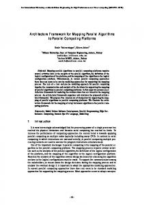
Figure 4. GPU-centric Video Coding Manager configuration for heterogenous systems equipped with accelerators containing single-copy engines.
Furthermore, the output data of one module is often the input data for another (e.g., the MVs from ME define the initial search point for the SME), which imposes additional data dependencies between the inter-loop modules. Hence, all the data-dependent inter-loop modules have to be sequentially processed (within a single frame). The only exceptions are ME and INT that can be simultaneously processed, since both of them use the CF and/or the RFs. According to the performance of the respective CPU and GPU parallel algorithms and inherent data dependencies [10], the inter-loop modules are divided in two groups, namely: i) ME, SME and INT modules; and ii) R* modules (i.e., MC, TQ, TQ−1 and DBL). Due to the low computational complexity of MC, TQ and TQ−1 modules (less than 3%) [4] and the limited possibility to collaboratively perform the DBL, the entire workload of the R* modules is assigned to a single (fastest) device, by applying the Dijkstra algorithm [9]. In fact, performing cross-device load distribution for modules with such a low computational complexity will result in increasing scheduling and communication overheads. In order to simplify the explanation of the derived collaborative video encoding procedure, the single-device mapping of the entire R* encoding block will be considered. For example, if a single GPU device is assigned to perform all the R* modules, the derived procedure is designated as GPU-centric and the GPU device is marked as “selected accelerator”, i.e., GPU1 . In contrast, a CPU-centric approach assumes that all the R* modules are performed on all cores. The configuration and overall functionality of the Video Coding Manager are determined in the initialization phase of the Framework Control and they depend on the identified accelerator capabilities, e.g., the amount of supported concurrency between the computation and communication. For example, Fig. 4 depicts the most common GPU-centric Video Coding Manager configuration for heterogenous systems with accelerators containing single-copy engines, as well as the orchestration of the Parallel Modules and data transfers. As it can be seen, the Video Coding Manager is responsible for invoking the modules and data transfers in a particular order, such that the correctness of the overall encoding procedure is guaranteed. Depending on the considered configuration, this module instantiates the parallel algorithms and maps them to several heterogenous devices, while specific input parameters (i.e., reference frames indexes) and parts
of the frame are supplied by the Data Access Management. The Video Coding Manager also provides the facilities to measure execution and transfer times, thus allowing Performance Characterization of the system resources. In respect to the previously referred inherent datadependencies, several cross-device synchronization points are defined (see τ1 , τ2 and τtot in Fig. 4). In brief, τ1 synchronization point reflects the dependency of the SME module on the outputs of ME and INT, while τ2 marks the completion of SME module and beginning of R* processing. The main objective of this framework is to minimize the total inter-loop video encoding time, i.e., τtot . In detail, the main functionality of the Video Coding Manager is as follows: •
•
τ1 denotes the time when the assigned portions of the ME and INT modules are processed on each device (according to the determined mi and li distributions from the Load Balancing block). This time also refers to the period when host to device transfers of the CF portions for ME (CF→ME) and for SME (CF→SME) are performed, as well as device to host transfers of the corresponding part of the interpolated SF (SF(RF)→SME) to ensure correctness of collaboratively processed SME. For accelerators not involved in the computation of the remaining R* modules (GPUi ), it is also required to fetch from the host the previously reconstructed RF before performing the ME and INT (RF), as well as to receive the remaining portion of the previously interpolated SF, SF(RF-1)→SME, to complete the SF at each accelerator. As shown in Fig. 4, these input and output data transfers are sequentially performed for accelerators with single-copy engine. For accelerators with dual-copy engine, SF(RF)→SME can occur in parallel with CF→SME transfers. The device to host transfers of the computed MVs also occur during this period (MV→SME), upon finishing the ME at each accelerator. It is worth noting that the proposed approach also exploits the parallelism across independent modules, i.e., ME and INT; τ2 represents the time when all heterogeneous devices finish the collaborative processing of the SME module (according to the determined si distributions). To sustain the cross-device SME parallel processing, the host to device transfers of the needed parts of the SF (SF(RF)→SME) are performed, as well as the missing MVs from ME (MV→SME), i.e., the needed MVs and SFs that were previously computed in the other devices. Moreover, the SME on all CPU cores can be started in this period, since all MVs are already present after the previously performed device to host transfers in τ1 . For the accelerator selected to compute the remaining R* modules (GPU1 in Fig. 4), the host to device transfers of the remaining parts of SF (SF→MC) and CF (CF→MC) are performed to ensure correctness
of the MC module, in parallel with SME on the selected accelerator. For the other accelerators (GPUi ), it must be guaranteed that not only the computation of the SME portion is finished, but also that the computed MVs are transferred back to the host (MV→MC); • τtot represents the overall inter-loop encoding time for a single inter-frame. In the period between τ2 and τtot the computation of the remaining R* modules needs to be finished, as well as the additional transfers of the remaining part of SF on the accelerators not selected to perform the R* modules (SF→SME+1). In the case when an accelerator is selected to compute the remaining R* modules (GPU1 in Fig. 4), it is firstly required to perform host to device transfers of the missing MVs from SME, which were computed on other devices (MV→MC). After R* modules are processed on GPU1 , the reconstructed RF (RF+1 ) is sent back to the host to allow its transfer at the beginning of the next interframe encoding on the other accelerators. 1) Parallel Modules: When orchestrating the video encoding procedure, the Video Coding Manager firstly performs a mapping of the instantiated Parallel Modules to different heterogeneous devices. To support a wide range of device architectures, an extensive library of highly optimized video encoding modules was specifically developed by relying on vendor-specific programming models and tools (i.e., OpenMP and SIMD intrinsics for multi-core CPUs, and CUDA/PTX for GPU devices). Parallel algorithms for CPUs do not only exploit the parallelism at the coarsegrained level (between the cores), but also the fine-grained data parallelism with SIMD instructions. Hence, different micro-architectures of multi-core CPUs, such as Intel Nehalem, Sandy/Ivy Bridge and Haswell, are supported by providing different implementations of each module based on Streaming SIMD Extensions (SSE) 4.2, Advanced Vector Extensions (AVX) and AVX2 vector intrinsics. In addition, different per-module parallelizations are also developed for different generations of GPU architectures (i.e., NVIDIA Tesla, Fermi and Kepler) by exploiting fine-grained data parallelism, as well by efficiently using the complex memory hierarchy. Hence, the adopted parallelization approaches do not only vary across different device architectures, but also due to different computational loads of the encoding modules, inherent data dependencies, locality and regularity of data access patterns. Considering the limited space in this paper, and the complexity of the proposed framework, the description of the developed parallel algorithms is not provided herein and further details can be found in [10]. 2) Data Access Management: As previously referred, the proposed framework also incapsulates specific mechanisms for device memory management and automatic data transfers in CPU+GPU systems via the Data Access Management. The functionality of this block is tightly coupled with the decisions taken by the Load Balancing routine. In order to
τ1 RF
GPUi
CF ME INT
ME CF SME
SF(RF) SME
τ2
τtot
SF(RF) SME
SF(RF-1) SME**
SME
MV SME
MV MC
mi-1
mi-1
mi
mi
si
H D
CF MC
SF(RF) MC
SF(RF) SME+1 m1
s1
∆m i
SF
produced
li-1 li
m1
s1
H D** si-1
si-1 li-1
li-1 li
H D**
MV ME
produced
mi-1 mi
H D
si D H
si-1 li-1
σir
li
si
MV MC
RF
∆m 1
H D
mi-1 mi
li-1
σi
∆li
li
l1
s1
H D mi-1
si
m1
s1
∆m i
mi
s1
∆l1
H D
H D si-1
l1
SF
li
si
H D
MV ME
H D si-1
MV SME
si-1
D H
MV SME
produced
si
si
produced
s1
s1 H D
H D
RF
RF
(a) GPUi Figure 5.
R*
CF H D
D H
τtot
SME
GPU1
H D
si-1
H D
CF
τ2
MV SME
D H
produced
(b) GPU1
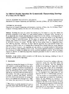
State of input/output buffers for accelerators with single-copy engine, when assigning mi , li and si loads with the proposed load balancing.
better depict its major functional principles, Fig. 5 presents the state of the input and output buffers (i.e., CF, SF, RF, MVs from ME and SME), for different accelerator roles, different parts of the encoding procedure and each synchronization point from Fig. 4. For the accelerators that are not responsible for computing R* modules (GPUi ), the previously reconstructed RF is received in the first part of the τ1 time interval, followed by fetching of CF portion according to the given mi amount of loads to process. As it can be observed, the amount of transferred data is equal to mi ×MB height×CF width and it must refer to the adequate CF position (offset). The offset is calculated according to the load distributions assigned to all other previously enumerated devices, which is symbolically represented as mi−1 in Fig. 5(a). At the same time, the SF part of size li ×MB height×SF width is interpolated and stored at the location calculated according to INT distributions assigned to other processing devices. The interpolated SF portion is then transferred to the host and the ME is performed on the previously received part of the CF to produce the mi ×MB height×MV width fraction of correctly displaced MVs. At this stage, the remaining part of the previously interpolated SF (during the encoding of previous inter-frame) is transferred to the accelerator (σir ). To ease the explanation of this procedure, it is represented in Fig. 5(a) as the SF remainder that is fetched in the next iteration (see dashed circled SF buffer, where the remaining portions are emphasized with dark solid colors). Moreover, during the τ1 time interval, additional CF portions are transferred to the host for SME. As it can be seen, depending on the computed CF offsets (in respect to the si distributions for previously enumerated devices) the amount of data to be transferred varies. Hence, in the particular case depicted in Fig. 5(a), it is required to perform two additional host to device transfers, to fetch the upper part of CF (region between si−1 and mi−1 ) and its bottom part
(region between mi and si ). In order to reduce the overall communication volume, the proposed framework integrates a specific procedure that maximizes the reuse of already available data on devices. It takes into account the relative distance between distributions from different modules for the same device, as well as the offsets from the previously enumerated devices, in order to determine the amount of additional data to be transferred when the load distributions for different modules refer to the data located in the same buffer [4]. This procedure is explicitly considered in the Load Balancing block via MS BOUNDS and LS BOUNDS routines to determine the amount of additional transfers ∆m i and ∆li , respectively. Finally, at the end of τ1 , the computed MVs from ME are transferred to the host. At the beginning of the τ2 interval, the additional part of the SF for SME (∆li ) is received (represented as two data transfers between li−1 and si−1 and between si and li in Fig. 5(a)). Similarly, additional MVs from ME (computed on other devices) are received (∆m i ), which is represented in Fig. 5(a) as two separate data transfers (between mi−1 and si−1 and between si and mi ). Furthermore, si ×MB height×MV width MVs, computed by the SME, are stored at the appropriate positions and subsequently sent to the host. For the accelerator that is selected to perform the R* modules (GPU1 ), the overall state of the input and output buffers does not significantly differ from the previously explained states for the other accelerators. However, as it is depicted in Fig. 5(b) at the end of the τ2 period for GPU1 , while the produced MVs in SME are stored, all remaining parts of SF and CF buffers are fetched from the host in order to allow the computation of MC (R*). Finally, in the period between τ2 and τtot , the remaining part of the SME MVs are also transferred from the host to the selected (GPU1 ) accelerator. This procedure is followed by the R* modules computation, where the complete RF is produced and transferred back to the host, in order to allow
a collaborative processing of the next inter-frame. During the same period, between τ2 and τtot , the other accelerators (GPUi ) receive the remaining part of interpolated SF (σi ), which size is determined in order not to surpass τtot −τ2 time limit (see Fig. 5(a)). This means that depending on the determined distributions and the amount of τtot −τ2 time, the assigned time slot for additional SF transfers might not be sufficient to transfer all the needed data, i.e., the complete upper SF region (until si−1 ) and the complete bottom SF region (from si to N ), as depicted in Fig. 5(a). Therefore, the remaining (not transferred) part of SF must be received in the τ1 period, while encoding the next inter-frame (i.e., SF(RF−1)→SME). C. Load Balancing and Performance Characterization In order to efficiently exploit the computation power of the heterogeneous devices, asymmetric bandwidth of communication links and the computation/communication overlapping, while dealing with the overall complexity of the video encoding procedure and inherent data dependencies, a specific Load Balancing routine is herein proposed. In general, the proposed procedure differs according to the type of device that is selected to perform the remaining R* modules and to the capabilities of the employed accelerators to support different amounts of concurrency between data transfers and kernel execution. Accordingly, Algorithm 2 describes the most commonly used GPU-centric variant of the Load Balancing routine for heterogeneous systems, with accelerators equipped with single-copy engine. The presented algorithm corresponds to the described configuration of the Video Coding Manager from Fig. 4, and to the functionality of the Data Access Management from Fig. 5. The proposed Load Balancing procedure is based on linear programming and it allows the distribution of the loads of the most computationally demanding modules (i.e., ME, INT and SME) and mapping of the R* modules by relying on realistic Performance Characterization of the system resources. In brief, the proposed load balancing approach determines the distribution vectors for each computationally intensive module, i.e., m={mi } for ME, l={li } for INT and s={si } for SME modules, with the amount of MB rows to be processed on each heterogeneous pi device and with the objective to minimize the total inter-loop video encoding time (τtot ). According to (1) from Algorithm 2, the sum of cross-device distributions for each module must be equal to the total number of MB rows (N ) within the frame. Two additional distribution vectors are also determined for each accelerator, i.e., σ={σi } and σ r ={σir }, i={1, . . . , nw }, to reflect the amount of additionally required data transfers (in MB rows) to complete the currently interpolated SF at each accelerator. Hence, the σ={σi } distribution vector reflects the amount of SF transfers that can be performed to each pi accelerator during the processing of the current inter-frame, i.e., without causing
Algorithm 2 Load Balancing for CPU+GPU video encoding Input: N, nw , nc , T1R∗ , Kim , Kil , Kis Input: K1rf dh , Kicf hd , Kirf hd , Kisf hd , Kisf dh , Kimvhd , Kimvdh , σir−1 Output: m={mi }, l={li }, s={si }, σ={σi }, σ r ={σir } Objective: minimize τtot nwX +nc
mi =N,
nwX +nc
i=1
li =N,
i=1
nwX +nc
si =N
(1)
i=1
∀i∈{nw +1, . . ., nw +nc } : m l li Ki +mi Ki ≤τ1 s τ1 +si Ki ≤τ2 cf hd m mvdh m1 K1 +m1 K1 +m1 K1 ≤τ1 sf dh mvdh m cf hd l ≤τ1 +m1 K1 +∆1 K1 l1 K1 +l1 K1 cf hd sf dh m cf hd mvdh m1 K1 +l1 K1 +∆1 K1 +m1 K1 ≤τ1 sf hd s l m mvhd +s1 K1 ≤τ2 τ1 +∆1 K1 +∆1 K1 cf hd sf hd sf hd m l m mvhd l ≤τ2 +(N −m1 −∆1 )K1 +(N −l1 −∆1 )K1 +∆1 K1 τ1 +∆1 K1 rf dh R∗ mvhd ≤τtot +T1 +N K1 τ2 +(N −s1 )K1
(2) (3) (4) (5) (6) (7)
(8) (9)
∀i∈{2, . . ., nw } : rf hd cf hd mvdh m ≤τ1 +mi K +mi Ki +mi Ki i i sf dh rf hd r−1 sf hd l m cf hd mvdh +li Ki +li K +σ K +∆i K +mi Ki ≤τ1 NK i i i i i
NK
(10)
NK
rf hd cf hd sf dh r−1 sf hd m cf hd mvdh +mi K +li K +σ K +∆i K +mi Ki ≤τ1 i i i i i i (12)
l sf hd m mvhd s mvdh τ1 +∆i K +∆i Ki +si Ki +si Ki ≤τ2 i sf hd l ) σi =MIN(N −li −∆i , (τtot −τ2 )/K i r l σi =N −li −∆i −σi
(11)
(13) (14) (15)
∀i∈{1, . . ., nw } : m ∆i =MS BOUNDS(m, s)
(16)
l ∆i =LS BOUNDS(l, s)
(17)
any additional overheads to the total time for collaborative video encoding. Correspondingly, σ r ={σir } represents the remaining data transfers (in MB rows) to be performed at each pi accelerator to fully complete the SF, which occur during the processing of the next inter-frame. Hence, the computed σ r ={σir } remainders for the current frame serve as inputs when processing the next inter-frame, which are designated as σ r−1 ={σir−1 } vectors in Algorithm 2. The performance of each pi device for the most computationally intensive modules is characterized with Kim , Kil , Kis parameters for ME, INT and SME modules. These parameters are expressed in processing time per MB row, obtained for the currently assigned loads in m, l and s distribution vectors. Hence, the parameters obtained during the encoding with the already determined distributions serve as inputs to the Load Balancing procedure to determine the next distributions, according to the iterative phase from Algorithm 1. Correspondingly, Kicf hd , Kirf hd , Kirf dh , Kisf hd , Kisf dh , Kimvhd and Kimvdh represent the obtained time per transferred MB row in different directions, i.e., from host to device (hd) or from device to host (dh), for CF, RF, SF and MVs. Depending on the device that is selected to perform the computations of the remaining R* modules, T1R∗ refers to the time required to perform the complete MC+TQ+TQ−1 +DBL sequence on the selected
60
60
40
CPU_H
GPU_F
GPU_K
SysNF
SysNFF
SysHK
30 20 10 0 32x32
40
CPU_N
CPU_H
GPU_F
GPU_K
SysNF
SysNFF
SysHK
30 20 10
64x64
128x128
Search Area Size [pixels]
256x256
(a) Different SA sizes (1 RF) Figure 6.
50
Performance [fps]
Performance [fps]
50
CPU_N
0 1
2
3
4
5
Number of Reference Frames
6
7
8
(b) Different number of RFs (32×32 SA).
Performance obtained with FEVES framework for different CPU and GPU device architectures and CPU+GPU systems for 1080p sequences.
device (GPU1 ). It is worth emphasizing that updating the Performance Characterization in runtime (after each processed frame) is particularly important for video coding on highly unreliable and non-dedicated systems, where the performance and available bandwidth can vary depending on the current state of the platform (e.g., load fluctuations, multi-user time sharing, operating system actions). According to the previously presented analyses, the minimization of the total inter-loop video encoding time τtot is attained by satisfying different conditions from Algorithm 2, for different synchronization points and heterogeneous devices depicted in Fig. 4 and 5. Due to the limited space in this manuscript, the overall Load Balancing functionality can be briefly summarized as follows: • (2) and (3) express the necessary conditions for multicore CPU execution in respect to τ1 and τ2 points; • (4)–(9) present the required conditions for the accelerator selected to perform the R* computations (GPU1 ), which guarantee that all input and output transfers, as well as kernel executions, are accomplished according to the defined synchronization points in Fig. 4 and 5; • (10)–(15) state the necessary conditions for the other employed accelerators (GPUi ) according to the execution scenarios presented in Fig. 4 and 5; • (16) and (17) correspond to the procedures to determine the amount of additional transfers when two different modules share the access to a single data buffer, i.e., for ME and SME accessing the CF and MV, and for INT and SME accessing the SF, respectively. IV. E XPERIMENTAL R ESULTS In order to evaluate the efficiency of the proposed framework and to challenge the real-time encoding for 1080p (full) HD video sequences on commodity desktop systems, the experimental evaluation was conducted on several different CPU and GPU device architectures, as well as on different configurations of CPU+GPU systems. The presented results were obtained by relying on a subset of optimized Parallel Modules for CPU and GPU architectures [9], [10] based
on H.264/AVC JM 18.4 reference encoder. The tests were performed on OpenSUSE 13.1 operating system with CUDA 5.5, Intel Parallel Studio 12.1 and OpenMP 3.0. Two different generations of quad-core CPU microarchitectures were considered: Intel Nehalem i7 950 (CPU N) and the newest Intel Haswell i7 4770K (CPU H) processors; while the GPU Parallel Modules were tested on two different NVIDIA architectures, namely: Fermi GTX 580 (GPU F) and Kepler GTX 780 Ti (GPU K). In terms of collaborative CPU+GPU processing environments, three different heterogeneous configurations were considered: i) SysNF, combining CPU N and a single GPU F; ii) SysNFF, with CPU N and two GPU F devices; and iii) SysHK, with CPU H and a single GPU K device. The proposed Load Balancing method was applied to encode different 1080p HD sequences (“Toys and Calendar” and “Rolling Tomatoes”) by strictly following the VCEG recommendations [11] for IPPP sequences, Baseline Profile, and Quantization Parameter (QP) of {27,28} for {ISlice, PSlice}. The video encoding performance was expressed in terms of the obtained encoding speed (i.e., time per frame or frames per second (fps)) and it does not significantly vary neither for different video sequences (due to FSBM ME) nor for different QPs (due to low complexity of the R* modules). In order to show the efficiency of the proposed framework when applying different video encoding parameters for different systems and device architectures, Fig. 6 presents the obtained experimental results when processing 1080p HD video sequences for four different SA sizes and different number of RFs. In all the presented charts, the shaded area represents the performance region where it is possible to achieve a real-time encoding. As it can be seen in Fig. 6(a), the overall performance of the inter-loop encoding significantly decreases between two successive SA sizes, due to the quadruplication of the ME computational load. It can also be observed that it is generally possible to obtain higher encoding performance by efficiently exploiting the improvements offered by the newest device architectures
Time [ms]
160
1RF
120
2RF
80 40
Real-‐4me video encoding 0 0
5
10
15
20
25
30
35
40
45
50
Frame Number
55
60
65
70
75
80
85
90
95
100
(a) Search area size of 64×64 pixels. 1RF
2RF
80
85
3RF
4RF
5RF
Time [ms]
60
40
20
Real-‐7me video encoding 0 0
5
10
15
20
25
30
35
40
45
50
Frame Number
55
60
65
70
75
90
95
100
(b) Search area size of 32×32 pixels. Figure 7. Performance obtained with the proposed adaptive Load Balancing routine when encoding the first 100 frames of “Rolling Tomatoes” sequence.
with optimized Parallel Modules (e.g., encoding on multicore CPU H is about 1.7 times faster than on CPU N, while GPU K outperforms GPU F for almost 2 times in terms of the encoding speed). In fact, the efficiency of the implemented Parallel Modules can also be evidenced in the possibility of achieving real-time encoding (≥25fps) for the smallest 32×32 SA size and 1 RF on both tested GPUs. On the other hand, for CPU+GPU systems, the proposed framework succeeded to efficiently exploit the synergetic performance of the heterogeneous devices for all the considered SA sizes by relying on the proposed Load Balancing strategy, thus significantly outperforming the corresponding single device executions. As a result, a real-time inter-loop encoding of 1080p sequences was achieved on all tested CPU+GPU systems for the SA size of 32×32 and 1 RF. In fact, a real-time encoding was even achieved for a higher and more challenging 64×64 SA on SysHK, which was not attainable with the state-of-the-art approaches [9]. To further challenge the real-time inter-loop encoding on the off-the-shelf desktop systems, Fig. 6(b) presents the performance obtained with the proposed framework when encoding 1080p HD sequences for different number of RFs and SA size of 32×32. As it can be observed, the proposed Load Balancing strategy allowed achieving a real-time encoding on all tested CPU+GPU systems for multiple RFs. In particular, a real-time encoding was achieved for up to 4 RFs on SysHK platform, outperforming the execution on both SysNFF and SysNF platforms. Furthermore, by relying on the proposed strategy for all the considered number of RFs, an average speedup of about 1.3 was obtained in the SysHK platform when compared to the single GPU K, and about 3 when compared to the multi-core CPU H execution. On the SysNFF platform, speedups up to 2.2 and 5 were obtained when compared to the GPU F and quadcore CPU N execution, respectively.
In order to provide a better insight on the capabilities of the proposed framework to dynamically adapt the load balancing decisions according to the current state of the execution platform, Fig. 7 depicts the obtained encoding time when processing the fist 100 inter-frames of a 1080p video sequence in SysHK platform for different number of RFs and SA sizes, namely: SA of 64×64 in Fig. 7(a) and SA of 32×32 in Fig. 7(b). In both cases, the time obtained when encoding the first inter-frame corresponds to an equidistant workload partitioning applied in the initialization phase of the Framework Control (see Algorithm 1), in order to obtain the initial Performance Characterization parameters for relevant system resources, such as the performance of heterogeneous devices and asymmetric bandwidth of the communication links. After the initial characterization is performed (in the iterative phase of the Framework Control), the proposed Load Balancing routine (see Algorithm 2) is invoked in order to distribute the loads corresponding to the Parallel Modules among all heterogeneous devices. As it can be observed, by relying on the proposed strategy, a significant reduction in the encoding time can be observed when subsequent inter-frames are processed, starting already with frame 2. In particular, a real-time encoding was attained in both cases for different number of RFs, i.e., 1 RF for 64×64 SA and 4 RFs for 32×32 SA, which was not achievable with an equidistant partitioning. Due to the higher computational complexity when encoding the inter-frames with larger SA size (64×64), the proposed strategy ensures a near-constant encoding time for all the processed inter-frames and considered RFs in Fig. 7(a). In the case of 32×32 SA size, the raising slopes can be observed in Fig. 7(b), when the encoding is performed with the number of RFs higher than one. For example, for 5 RFs, the encoding time is increasing with the number of encoded inter-frames at the beginning (frames 2-5), while it becomes
near-constant after the fifth inter-frame. The rationale behind this behavior lies in the fact that a single RF is produced during the encoding of a single inter-frame (see Fig. 5). Hence, for encoding with a higher number of RFs, it is required to firstly process several inter-frames, in an amount that must be greater or equal to the specified number of RFs. During the processing of these initial inter-frames, the number of considered RFs increments with each processed inter-frame, until reaching the specified number of RFs. Therefore, Fig. 7(b) shows the ability of the proposed Load Balancing strategy to efficiently distribute the loads and achieve a high encoding performance, while simultaneously dealing with this increasing problem complexity. An interesting phenomenon was observed during the encoding with 1 RF (frames 76 and 81) and 2 RFs (frames 31, 71 and 92), where a sudden change in the system performance occurred (e.g. other processes started running). Still, the dynamic Performance Characterization of the proposed framework allowed capturing this unexpected performance change, thus resulting in a successful load redistribution according to the new state of the platform. This is emphasized by a very fast recovery of the performance curves, which required a single inter-frame to converge to the regions with stable load balancing decisions. This ability of the proposed framework to provide stable distributions, despite sudden system performance changes, highlights the self-adaptability characteristics of the presented approach. Finally, it is also worth emphasizing that the scheduling overheads (introduced by the proposed framework) take, on average, less than 2ms per inter-frame encoding, which is significantly less than the time required to individually execute any inter-loop module. V. C ONCLUSIONS In this paper, an autonomous video encoding FEVES framework for multi-core CPU and multi-GPU platforms is proposed. To challenge a real-time H.264/AVC interloop video encoding on these systems, adaptive scheduling and load balancing methods were integrated that explicitly take into account the overall complexity of the video encoding procedure, while efficiently exploiting several levels of concurrency between computation and communication. The support for a wide range of different CPU and GPU architectures is provided via specifically developed encoding library with highly optimized algorithms for all inter-loop modules. The proposed unified framework also incorporates simultaneous execution control across different heterogeneous devices and automatic data access management to minimize the overall communication volume. By relying on dynamic performance characterization for heterogeneous devices and communication links, the presented framework was capable of iteratively improving the load balancing decisions and adapting to the performance changes in nondedicated systems. The efficiency of the proposed frame-
work was experimentally evaluated in different CPU+GPU platforms, where a real-time video encoding of 1080p HD sequences was obtained even for more challenging video encoding parameters, such as 64×64 SA and/or multiple RFs. Finally, the FEVES framework was capable of outperforming a single-device execution for several times, while introducing negligible scheduling overheads. ACKNOWLEDGMENT This work was supported by national funds through FCT – Fundac¸a˜ o para a Ciˆencia e a Tecnologia, under projects PEst-OE/EEI/LA0021/2013, PTDC/EEIELC/3152/2012 and PTDC/EEA-ELC/117329/2010. R EFERENCES [1] Cisco, “Cisco visual networking index: Forecast and methodology, 2012-2017,” White Paper, May 2013. [2] J. Ostermann et al., “Video coding with H.264/AVC: tools, performance, and complexity,” IEEE Circuits and Systems Magazine, vol. 4, no. 4, pp. 7–28, April 2004. [3] G. J. Sullivan, J.-R. Ohm, W. Han, and T. Wiegand, “Overview of the high efficiency video coding (HEVC) standard.” IEEE Trans. Circuits Sys. Video Technol., vol. 22, no. 12, pp. 1649–1668, 2012. [4] A. Ilic, S. Momcilovic, and L. Sousa, “Scheduling and Load Balancing for Multi-module Applications on Heterogeneous Systems,” INESC-ID, Technical Report, February 2014. [5] Y. Ko, Y. Yi, and S. Ha, “An efficient parallelization technique for x264 encoder on heterogeneous platforms consisting of CPUs and GPUs,” Journal of Real-Time Image Processing, pp. 1–14, 2013. [6] R. Rodr´ıguez-S´anchez, J. L. Mart´ınez, G. Fern´andezEscribano, J. L. S´anchez, and J. M. Claver, “A fast GPUbased motion estimation algorithm for H.264/AVC,” in Advances in Multim. Modeling. Springer, 2012, pp. 551–562. [7] J. Zhang, J. F. Nezan, and J.-G. Cousin, “Implementation of Motion Estimation Based on Heterogeneous Parallel Computing System with OpenCL,” in Proceedings of the IEEE Int. Conf. on High Perf. Comp. and Comm., 2012, pp. 41–45. [8] B. Pieters, C. F. Hollemeersch, P. Lambert, and R. Van De Walle, “Motion estimation for H.264/AVC on multiple GPUs using NVIDIA CUDA,” in Society Photo-Optical Instrumentation Engineers, vol. 7443, 2009, p. 12. [9] S. Momcilovic, A. Ilic, N. Roma, and L. Sousa, “Dynamic load balancing for real-time video encoding on heterogeneous CPU+GPU systems,” IEEE Trans. on Multimedia, vol. 16, no. 1, pp. 108–121, 2014. [10] S. Momcilovic, N. Roma, and L. Sousa, “Exploiting task and data parallelism for advanced video coding on hybrid CPU+GPU platforms,” Journal of Real-Time Image Processing, pp. 1–17, 2013. [11] T. Tan, G. Sullivan, and T. Wedi, “Recommended simulation common conditions for coding efficiency experiments - revision 3,” ITU, VCEG, Doc. VCEG-AI10, July 2008.