Final Technical Report Quantification and Standardization of Pattern Properties for the Control of the Lost Foam Casting Process DE-FC36-02ID14235 Project Period 06/03/02 through 06/02/05 Principal Investigator Dr. Ronald Michaels Industrial Analytics Corporation 865 573 5843
[email protected] Recipient Organization: Industrial Analytics Corporation 10233 Chapman Hwy. Seymour, TN 37865 Co Investigators Dr. Roberto Benson The University of Tennessee 865 974 5347
[email protected] Dr. Dayakar Penumadu The University of Tennessee 865 974 2355
[email protected]
September 30, 2005
Acknowledgment: This report is based upon work supported by the U.S. Department of Energy under Award No. DE-FC36-02ID14235. Disclaimer: Any findings, opinions, and conclusions or recommendations expressed in this report are those of the authors and do not necessarily reflect the views of the Department of Energy. Proprietary Data Notice: No proprietary data is contained in this report.
Table of Contents Executive Summary List of Appendices Introduction Background of Researchers Report of Activities Comparison of Proposed vs. Actual Tasks Commercialization Publications Web Site Conclusions
Executive Summary The subject of this report is work done in the improvement of the Lost Foam Casting Process. The original objective of this project was to improve the control of metal fill by understanding the influence of foam pattern and coating properties on the metal fill event. Relevant pattern properties could then be controlled, providing control of the metal fill event. One of the original premises of this project was that the process of metal fill was relatively well understood. Considerable previous work had been done to develop fluid mechanical and heat transfer models of the process. If we could just incorporate measured pattern properties into these models we would be able predict accurately the metal fill event. As we began to study the pyrolysis behavior of EPS during the metal fill event, we discovered that the chemical nature of this event had been completely overlooked in previous research. Styrene is the most prevalent breakdown product of EPS pyrolysis and it is a solvent for polystyrene. Much of the styrene generated by foam pyrolysis diffuses into intact foam, producing a molten gel of mechanically entangled polystyrene molecules. Much of the work of our project has centered on validation of this concept and producing a qualitative model of the behavior of EPS foam undergoing pyrolysis in a confined environment. A conclusion of this report is that styrene dissolution in EPS is a key phenomenon in the pyrolysis process and deserves considerable further study. While it is possible to continue to model the metal fill event parametrically using empirical data, we recommend that work be undertaken by qualified researchers to directly characterize and quantify this phenomenon for the benefit of modelers, researchers, and workers in the field. Another original premise of this project was that foam pattern and coating properties could be used to efficiently control metal fill. After studying the structure of EPS foam in detail for the period of this contract, we have come to the conclusion that EPS foam has an inherent variability at a scale that influences metal fill behavior. This does not allow for the detailed fine control of the process that we originally envisioned. We therefor have sought other methods for the control of the metal fill
event. Of those, we now believe that the magnetic metal pump shows the most promise. We have conducted two casting trials using this method and preliminary results are very encouraging. A conclusion of our report is that, while every effort should continue to be made to produce uniform foam and coatings, the use of the magnetic metal pump should be encouraged and closed loop control mechanisms should be developed for this pouring method.
Introduction The technology of Lost Foam Casting is deceptively simple. An EPS pattern is molded and then coated with a permeable ceramic coating. The pattern is embedded in sand and filled with metal. As always, the devil is in the details. Patterns are not always the same, coating changes over the weekend, sand temperature or compaction changes, the metal changes. Previous work has demonstrated that sand temperature and compaction can be controlled, clean metal works better. The last big frontier of the process was thought to be the “white side” of the process. If we could just understand the influence of pattern properties on the metal fill event, we could bring the entire process under control. The questions were simple; how do we measure foam properties so that we can make uniform foam; how do we control the foam manufacture process so we can make the same good foam all the time? With pattern production under control, the process could be tuned and controlled. In order to measure and control the relevant properties of EPS foam it is necessary to understand the influence of the property under measurement on the metal fill event. While performing initial characterization work we determined that the then current understanding of the pyrolysis behavior of EPS foam was deficient and not in accord with fundamental chemistry. We then decided that to follow a strictly empirical or phenomenological approach would not produce long term results because without a fundamental understanding of the underlying processes, every casting would be different, precise casting modeling and validation would not be possible and ultimately the process could not be brought under control. We decided to follow the chemistry. The outcome of this is the Gel Front Hypothesis. Our physical characterization of EPS foam showed us that a strong, unavoidable randomization element was present in the production of EPS foam. While there are many reasons for this random element, the relatively large size of expanded foam beads as compared to the thickness of the pattern and the resulting casting is a contributing factor. Another factor is the effect of nonuniform foam properties on the stability of the gel front. We then began to look for ways to deal with the inherent randomness of foam patterns. We make two recommendations; one, investigate
the use of smaller EPS beads and two, investigate bead fill enhancement methods. We have demonstrated one method of bead fill enhancement; we understand that work is underway by others to develop improvements to the bead fill process. If we accept the idea that patterns have an inherent random aspect, how can we control the metal fill event? The gravity fill method is inherently uncontrollable; by the time the metal gets to the pattern it is beyond any control mechanism other than foam and coating. Of course geometry, gating, chills, and lighteners have all been used to control the overall process; however, there is no way to control gravity metal fill for each individual pattern using a closed loop control system. Vacuum assist or low-pressure fill systems have a large pneumatic cushion that controls the metal flow. These methods necessarily have a large time delay between control change and reaction at metal front. Also, the presence of a mass (the liquid metal) and a spring (the compressible gas) can produce a low frequency resonant effect. After consideration we determined that the magnetic metal pump showed the most promise. We have conducted two casting trials and we have shown that metal head can be varied during the fill event. Our second trial indicates that metal fill rate can be measured. It is our conclusion that further work should be undertaken to develop a closed loop measurement and control system to control the metal fill of each individual lost foam pattern. This may have applicability to other casting processes. The original energy savings were conceived as reducing casting scrap and re-melt energy by controlling the process using foam and coating properties. We now believe that while pattern properties must be held consistent, the real energy saving lies in closed loop control of each metal fill event. Besides controlling metal fill, the magnetic metal pump can fill from the bottom of the flask, saving energy now spent in re melting cut off fill sprues.
Background of Researchers Our project team consisted of the Industrial Analytics Corporation (IAC) PI and two researchers from The University of Tennessee (UT). Dr. Ronald Michaels of IAC is an expert in the application of modern computational methods in Engineering. He developed the low energy x-ray radiographic system used in the investigation of the detailed structure of EPS foam. Dr. Roberto Benson of UT is a Polymer Chemist. Dr. Benson has a background in biomedical applications of polymers. He developed the Gel Front hypothesis. Dr. Dayakar Penumadu of UT is a Civil Engineer. He is an expert on permeable systems and conducted our work on foam permeability and coating properties.
Report of Activities Introduction Broadly speaking our Project Goals were as follows: •
Define and Justify a Science Based Hypothesis of EPS Pattern Behavior during Metal Fill
•
Define and Demonstrate Characterization Technologies that Relate to Hypothesis
•
Utilize Measured Properties of Patterns as Input to Hypothesis.
Our Original Project Concept may be summarized as follows: •
Metal fill can be controlled by measuring, modifying and controlling pattern properties
•
Our underlying understanding of the LFC process was sufficient to support applied research
•
Local metal front behavior is determined by local pattern properties.
Now that we have reached the end of the project, we summarize our Project Concept as follows: •
The Gel front is the determining factor of EPS foam decomposition during metal fill of the pattern
•
Metal fill can and should be controlled by a combination of: •
pattern properties
•
metal flow and pressure control.
In this project we have used the structure, properties, processing method. As we understand any one of the three, it increases our knowledge of the other two. Our Report of Activities is outlined as follows: •
Origin and Properties of Expanded Polystyrene Foam
•
Thermal Characterization of EPS Foam
•
Gel Front Hypothesis
•
Casting Trials
Origin and Properties of Expanded Polystyrene Foam Polystyrene is a long chain hydrocarbon made up of many repeating elements of a monomer, styrene. The below figure shows the chemical structure; the actual physical structure of an EPS molecule is similar to a long curved piece of spaghetti.
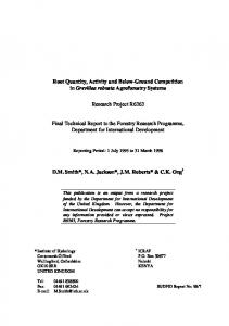
Raw beads consisting of high molecular weight polystyrene (180,000 -300,000) and 5 - 8% low boiling aliphatic hydrocarbon blowing agent, i.e. Pentane, are prepared as a feed material to the pre-expansion process. The below figure illustrates the process. Pre-expansion •
Pentane infused beads are heated above glass transition temperature
•
Pentane expands and forms bubbles in bead
•
Polymer molecules are stretched like springs
•
Expanded beads are cooled
•
Stretched EPS molecules are frozen into place
Pattern Molding •
Pre Expanded beads are blown into a mold
•
Steam is applied to the beads
•
Residual pentane expands beads
•
Beads adhere along planes of contact by polymer chain entanglement
•
Time and temperature of heat application as well as pentane content of bead determine degree of bead expansion and “fusion”
•
Heat is removed and foam allowed to cool
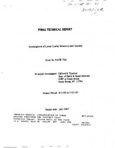
The interior structure of EPS beads is made up of many small internal cells with porous walls as shown in the below figure.
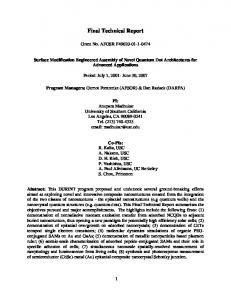
The fracture morphology of foam is shown in the below figure. Note the structural differences that occur as a result of varying autoclave steam time from 4.5 seconds to 6.5 seconds. As steam time increases the open volume or void space around the beads decreases. This produces measurable effects in gas permeability, oil uptake, heat transfer, surface finish, light transmission, tensile strength, and other properties.
The mechanism of bead fusion is polymer chain entanglement. As the pre expanded beads are heated above their glass transition temperature main chain vibratory motion increases and polymer chains from adjacent beads can become entangled. This can be seen in the below figure that shows molded foam after a subsequent application of heat raises the foam temperature above the glass transition temperature. Without the pressure of residual pentane, the stretched polymer chains contract. Where polymer chains from adjacent beads are entangled, the necking occurs.
The temperature/bead size relationship has been investigated and the below figure shows the result of an experiment using infrared light to heat a single bead. The bead was monitored using a video camera and measurements were made from those images and plotted. This experiment illustrates that when EPS foam is heated above its glass transition temperature, the molecules that were stretched during the molding process seek to contract, just as any other spring.
Detailed Structure of EPS Foam We report on several methods that we have developed for characterizing the detailed structure of EPS foam. •
Optical transmission
•
Structured surface lighting
•
X-ray Radiography of foam
•
X-Ray Radiography of oil filled interstitial space
Optical Transmission the phenomenon used for optical transmission measurements is the preferential transmission of light through interstitial spaces. In this technique, bead joints act as a light transmission channel. As joints close up with greater steam time, light transmission through bead joints decreases contrast between beads and bead joints. The relative intensity of bead surface vs bead joint can be measured by digitizing images and applying analysis methods: •
low fusion: high contrast between beads and joints
•
high fusion: low contrast between beads and joints
One of the most common patterns is small regions of regular bead arrangement with transition zones between regions. This is similar in appearance to crystallization but cannot be due to the same basic mechanisms because there is not any powerful inter bead attraction that would be comparable to the atomic or molecular attractions present in crystal formation. Another common occurrence is large openings in random locations. The locations are caused by bead stacking that produces a space too small for an impinging bead to fill. These locations become filled with coating and produce coating penetrations into the cast part. The difference between low steam time and high steam time foam is illustrated in the two below figures. From these typical foam images, one can conclude that EPS foam has a strong random component. Also note that where steam vents are visible the light contrast decreases. That is due to greater expansion of the beads in those areas during pattern steaming.
Structured Surface Lighting In this technique, the surface of the foam is illuminated from the side, casting shadows into depressions in the foam. The illustration of this technique uses a Line Source Illumination of the Front Surface of the foam. This surface is then imaged using a high resolution scanner. Because the shadows cast by the illumination can be seen by the camera the degree of foam finish is apparent and can be characterized. Surface voids that will become coating penetrations are visible. This can be a non contact automated inspection method for foam patterns The below figure shows the arrangement of a structured light setup. The following figure shows a low steam time and high steam time foam for comparison. As one might expect, at higher steam time the surface finish is smoother. Prior to this project, the Principal Investigator characterized foam using a numerical measure of digitized foam images. This has potential to be a nondestructive foam characterization tool. It might find application in determining locations of deep coating penetration in thin foam sections.
X-ray Radiography of Foam X-Ray radiography has been used to image sections of EPS foam. By using a high resolution digital x-ray camera it is possible to capture detailed images of foam. By using calibration methods these images can be converted into density values. Each pixel in the camera captures the average density of the small region of foam through which x-ray photons travel to that pixel from the x-ray generator. •
•
Pattern density determined by: •
density of pre-expanded beads
•
packing fraction of beads into mold
•
surface effects
•
differential application of thermal energy
Density can be measured for a wide range of size scales to show: •
Overall pattern density variations
•
Local structure
The principles of x-ray radiography are illustrated in the below figure. X-Ray photons are emitted from an x-ray generator that acts as an effective point source. The x-ray beam is attenuated by the EPS foam and the resulting silhouette is captured by the x-ray camera, a 2D digital image capture chip. The digital data is used to compute the local density of the EPS foam based on calibration data.
Below is a typical x-ray image of a small section of EPS foam. This image is used to make the point that bead arrangement is essentially random.
X-Ray Radiography of oil filled interstitial space In order to visualize the interstitial space between beads, olive oil was allowed to diffuse up into intact foam. The below figure shows the effective connectivity of void space within the foam by showing the olive oil. Note that open void space is random in nature with no regular pattern.
In addition to the above detailed images of foam structure, we have investigated the internal structure of EPS foam patterns by deliberately removing fine detail in order to make bead scale structure stand out. In the below image bead boundary details are filtered out and bead scale phenomena become apparent. Light spots indicate voids in foam that occur during bead fill of mold. Some voids are near bead size. Higher packing fraction can minimize this effect. The image is of a Saturn 4 valve engine spark plug hole and surrounding combustion chamber.
Sphere Packing Simulation In order to understand how sphere packing occurs, one of Dr. Penumadu's graduate students wrote a sphere packing simulation program that models spherical particles in a gravity field. This simulation could be modified to simulate EPS beads in air currents. One result of those simulations will be shown: the effects of walls spaced close together relative to sphere diameter. The below figure illustrates the simulation. For a given wall spacing, a range of sphere diameters was used for the simulations. As larger spheres are placed in the container, the packing fraction decreases. This is a very real effect of the close proximity of a wall limiting the positions that individual beads can achieve.
The results of the computations are shown in the below figure. Wall effect phenomenon indicates use of smaller beads for same wall thickness casting in order to achieve higher packing fraction and smoother surface with fewer penetrations.
Other bead fill enhancement methods should be investigated in order to compensate for lower inherent packing fraction of thin wall sections. See below for high energy sound vibration as an example of how bead fill enhancement might be done. The example is an 8mm GM test plate. High energy sound waves were introduced at the upper fill gun location. The pattern was steamed and subjected to x-ray radiographic analysis.
The below figure shows the resulting plate. Darker is denser. The lighter disc at the fill port indicates fill gun projection into pattern. The darker circular region around the upper fill port indicates greater bead packing density that results from sonic vibration during fill. Further development will be required to provide uniform bead fill enhancement over the volume of a pattern.
The Nature of Bead Fusion During pattern steaming, EPS molecules are raised above their glass transition temperature. This induces main polymer chain motion. Where adjacent beads are pressed together by bead expansion, areas of molecular chain entanglement form. Chain entanglements can only be resolved by force, chain scission or high temperatures. The lifetime and strength of an entanglement at temperatures below Tg, the glass transition temperature, is very long. Therefor, once foam has been molded its shape is fixed. There is, of course, the normal slight shrinkage after molding. Chain entanglements have a profound effect on the flow (viscosity) and mechanical properties of the EPS polymer. Entanglements contribute directly to the changes in the modulus of elasticity. At small deformations no entanglement effects are apparent, At large deformations the ultimate strain and energy of fracture is strongly dependent on chain entanglements. This is apparent in the tensile tests reported later in this report.
Using a combination of SEM and radiographic imaging we show details of the formation of regions of physical chain entanglement during the pattern steaming process. In the below figure the physical process of bead fusion is illustrated.
This suggests that bead joint size is a primary measure of the degree of fusion that results from a given pattern steam time. In the below figure this concept is illustrated by showing the same region on three patterns that have different steam times. This clearly illustrates that greater steam time produces larger areas of bead fusion. In this figure the curved surface is the side of a spark plug hole. The dark lines are fused bead surfaces that are parallel to the direction of the x-ray beam.
Our conclusion is that digital x-ray radiography is a powerful tool for the laboratory evaluation of EPS foam properties. A properly shielded x-ray system produces no measurable radiation outside its cabinet; however, because of the regulatory issues surrounding the use of x-ray systems in a factory setting, this is a method best applied in a laboratory setting.
Tensile Strength Tests In order to characterize the bead fusion process we developed a tensile test apparatus that allows us to measure polymer chain entanglement formed during pattern steaming. As a part of the development process, special dogbone shapes and grips were developed. Steam time of foam samples varied from -9 (normal time - 9 seconds) to + 3 (normal time + 3 seconds) In the below figure, the special dogbone shape developed for this measurement is shown.
An overall view of the testing apparatus is shown in the below figure.
The results of the testing program are shown in the two following figures. In each figure, reference is made to a steam time that is normal (N), greater than normal by 3 seconds (+3), less than normal by 3 (-3), 6 (-6), or 9 (-9) seconds. The stress strain curves for the various steam time foams are closely overlayed in the elastic range. This uniform modulus of elasticity over the steam time range indicates that mechanical foam testing is not a good candidate for nondestructive production testing of foam because interesting differences only occur at fracture. In the summary of results, peak stress and strain values indicate that mechanical foam testing can be a useful destructive test of foam. As
steam time increases, peak values increase. Our conclusion is that tensile testing is a potentially useful destructive method for characterizing EPS foam, but is not useful for nondestructive testing because of the similarity of behavior of foam in the elastic range.
Foam Permeability Tests Foam permeability is an indirect measure of degree of polymer chain entanglement and surface area that is entangled. Permeability is a bulk measure related to Connected Void Space and it is an indicator of the level of gas flow through intact foam during the metal fill event. In the work described here permeability was measured using gas flow through sample, from molded surface to molded surface. Specialized equipment was developed at The University of Tennessee for this purpose. The system is shown in the below figure.
Samples of foam having different levels of steam application during the pattern molding process were tested. The range was meant to cover very “underfused” to “overfused.” The below table summarizes the samples of foam that were used for this test. Reference is made to a steam time of 17 seconds that is normal (N), greater than normal by 3 seconds (+3), less than normal by 3 (-3), 6 (-6), or 9 (-9) seconds.
The results of the tests are shown in the below figure. It is clear that as steam time increases, the gas permeability of foam decreases. This is a reflection of the fact that as steam time increases, the volume of connected void space decreases. It is the connected void space that provides the pathway for gas transport, so this is as expected. We conclude that measurement of gas permeability is a reliable indicator of connected void space in EPS foam.
Foam - Coating Structure In this section three ideas are explored: •
Coating Thickness vs. Foam Surface
•
Coating Penetrations into Foam
•
Affect of thicker coating and penetrations on metal fill.
The below figure shows the surface of a lost foam casting that has penetrations of coating into the surface of the metal. It is well known from Strength of Materials that such penetrations are stress risers. As such they are potential failure points. Additionally, on a thin part penetrations from opposite surfaces that are connected will produce a “leaker.”
The thickness of coating was measured using an optical technique and an x-ray radiography technique. The optical technique is illustrated in the below figure. The foam is cut perpendicular to the coated surface and the cut edge is imaged using a digital camera. The resulting image is analyzed automatically and a coating thickness value is determined. This destructive laboratory test has been applied at one of the General Motors casting plants.
In the x-ray radiographic method the area distribution of coating is visualized. Two methods of viewing the coating were developed. The first of these involves placing a piece of coated foam in the x-ray beam so that one surface is parallel to the x-ray beam. Please recall that the x-ray generator produces a cone beam as opposed to the parallel beam produced by linear accelerators; therefore, only one surface can be parallel to the beam in one view. The two below figures provide edge views of high fusion and low fusion 8mm GM Test Plates. The dimension along the viewing surface is 18mm.
From these two images we may conclude that coating thickness is greater on a low fusion pattern. The low fusion pattern has more and deeper coating penetrations; due to the larger interstitial void spaces that are a property of lower steam time foam. This edge view does not provide information about the location of the penetrations on the surface of the pattern.
The same pieces of foam were rotated 90 degrees and x-ray images were captured that show the location of penetrations in the plane of the pattern surface. Those two figures are shown below. The first figure shows the low fusion coated sample. Note that in this view, front and rear coated surfaces are superimposed. The below image, when viewed with red/cyan glasses shows a stereo view of the coating penetrations that provides a way to distinguish between front and rear surfaces.
The below figure shows the high fusion plate section. Note how clearly the steam vent locations are shown as areas of thinner coating. When viewed with red/cyan glasses a stereo view of the coating penetrations may be seen.
Coating penetrations may be minimized by using smaller EPS beads to minimize thin wall effects, use of bead fill enhancement techniques, and greater steam time (consistent with other requirements). It is important to note that if penetrations occur from both surfaces on a thin section, it is a statistical certainty that in a percentage of castings two penetrations will be located opposite each other – producing a high probability of a “leaker.”
Thermal Characterization of EPS Foam Our objective in this work was to determine the overall thermal resistance from the metal front to ambient temperature intact EPS pattern foam. The below figure illustrates the approach. Note that this figure was prepared prior to work on the gel front hypothesis; the region indicated as Cross-linked Globs is now known to be a mechanically entangled gel made up of EPS with styrene diffused into it.
A new experimental procedure was developed for characterizing the thermal conductivity of Expanded Polystyrene Foam. As a first step, it is important to visualize the detailed structure of EPS foam and interpret it from a heat transfer perspective. The below figure summarizes the modes of heat transfer through EPS foam.
A foam sample can be considered as a composite with two phases (air with a thermal conductivity of 0.0338W/m.K at 400K, and polystyrene with a thermal conductivity of 0.16W/m.K at 400K). Because of morphological changes in foam due to differences in steam time, we would expect to see differing contributions of these two phases. The below table illustrates that this is in fact the case. As steam time goes up, we see higher temperatures in the interior of the foam.
The following form of equation is proposed to model variation of temperature as a function of distance (constants will thus describe a particular foam type with a given fusion level):
Differential Scanning Calorimetry A series of Differential Scanning Calorimetry (DSC) experiment were run to demarcate EPS bead collapse temperature range. Experiments covered the range of approximately 110°C ~ 140 °C. The DSC instrument was used to heat up “Normal” foam samples to specific temperature values, under controlled heating rate and morphological variations were studied. The below table summarizes observations relating to foam morphology. Note that all of the morphology changes occurred without the addition of styrene vapor and only approximate the nature of changes that we might expect to see in actual foam under metal fill conditions.
While DSC was found to be a method for characterizing morphological changes in EPS foam vs. temperature, it is an inappropriate instrument for consistently measuring thermal properties in EPS foams. The incompatibility arises due to discontinuous sample contact with DSC crucible during an experiment. A small volume reduces the problem but due to low density the sample mass is low and that gives rise to erroneous transition and phase change enthalpies. A taller crucible has problems of steep thermal gradients within the sample even at lowest allowable instrument heating rates. We recommend that DSC be used only for determining temperature ranges of morphological and phase changes. Multiphase Degradation Model The below figure shows our proposed model of events in the region between the metal front and intact foam. There is a very high convective heat transfer coefficient in metal-gas and foam-gas interfaces due to fast evolution of gases and turbulence. Attenuation of radiation by the volatile matter provides energy for endothermic chemical breakdowns and superheating of the volatile monomers and other gaseous products present in the gas front. Bulk radiation from volatile polymer molecules at temperatures >320° C must be taken into account. (eg. ε of water vapor can be as high as 0.6 at pwL = 10ft.atm at 600 °C).
The degradation of intact foam is a combined effect of heat transfer and solution kinetics of volatile matter. The below figure illustrates our proposed model of how foam degradation is initiated.
Characterization of the Thermal Degradation Products of Polystyrene Polystyrene, when subjected to temperatures in excess of 300 oC, undergoes chain scission, depolymerization and both intra and inter molecular transfer. In the temperature range Tg< T < Td , polystyrene exhibits changes flow properties, i.e., viscosity Polystyrene is an amorphous polymer and therefore, does not have a melting temperature. Further, the presence of styrene has a strong effect on the temperature response of EPS. Two depolymerization processes are at work during foam degradation: Unzipping of polymer chain -generation of volatiles (e.g. styrene monomer) Random chain scission- generation of oligomers (short molecular chain fractions). Depolymerization is a highly endothermic reaction that has a strong dependence on residence time, pressure, heating rate and baseline temperature. The below figure illustrates the various possible results of the depolymerization of EPS foam.
When polystyrene is decomposed, a number of byproducts are formed. The below table shows the byproducts when decomposition occurs at 740 degrees Celsius. Note that styrene is the most common single byproduct at 71%. Product
Weight %
Hydrogen Methane Ethylene Ethane Propene Pentene and Hexene Benzene Toluene Xylene and Ethylbenzene Styrene Naphthalene Carbon Dimers, Trimers, and higher molecular weight compounds
0.03 0.3 0.5 0.04 0.02 0.01 2.1 4.5 1.0 71.0 0.8 0.3 15.0
Polystyrene Byproducts Ref: W. Schnabel, Polymer Degradation: Principles and Practical Applications, Hanser Publishers, Munich, 1981 Another published reference shows a styrene byproduct of 40%. (Ref. N. Grassie, Chemistry of High Polymer Degradation Processes, Interscience Publishers, Inc. N.Y.p79, 1956). Under flash pyrolysis conditions, styrene monomer yield is approximately 80%. (ref. Shivkumar et al. 1995). While the percentage of styrene in the pyrolysis products vary, one thing that remains constant is that styrene is the single largest product.
One point that we cannot overemphasize is that Styrene is a Solvent for Polystyrene. Therefore, the behavior of EPS in a closed volume with styrene present is fundamentally different from unconfined EPS thermal degradation. This fundamental fact leads to the Gel Front Hypothesis. The below figure shows the difference in foam morphology before and after exposure to styrene vapor.
The following series of figures illustrates the difference in degraded foam with and without the presence of styrene.
The below figure shows the effects of styrene at bead joints. The styrene is opening up diffusion channels
By inspecting the above images one can conclude that the presence of styrene has a strong effect on the morphology of EPS foam. The confined environment in the region of the metal front precludes large volumetric losses of styrene (Tb=145 oC) vapor. Styrene diffuses into the EPS foam at the metal front. The absorption of styrene leads to loss of EPS foam structure integrity and the lowering of the glass transition temperature of the EPS foam. A series of experiments were conducted with identical foam samples from 10mm thick EPS plates. The first set of samples were exposed to radiation and convection air current from a molten aluminum source at 750ºC. The second set was exposed to styrene vapor from a boiling liquid styrene source in a beaker, at a temperature of 145ºC. Radiation effects at 145ºC were neglected. Foam actually started to collapse after 30 seconds of exposure to air while the collapse was immediate (2 sec) in case of styrene exposure. GPC of the experimental samples are identical to the initial foam that clearly implies the absence of any chemical depolymerization. The result explains the formation of the gel front since the polymer expands in a styrene (and its oligomers) solution and near the end of the casting process we should expect a substantial amount of nondegraded polystyrene in solution. This is important in the analysis of metal fill modeling as it is the mechanism for slowing of fill as the metal nears the end of the pattern volume. Folds may be caused in part by trapped pockets of gel, rather than “tar like residues.” Certainly, the pyrolysis of EPS is not a fractional distillation process where lower molecular weight molecules are boiled off; it is a depolymerization process where long chain molecules break apart into shorter, lower weight molecules.
The diffusion of styrene away from the metal front into intact foam is illustrated using a partially filled GM test plate. The below figure shows the styrene content of foam at various distances from the metal/gas front. An additional figure for a reference pattern is shown as a benchmark of how much styrene is naturally present in an EPS pattern. It is clear that styrene diffuses away from the metal front into intact foam. It is also clear that there is no direct path for gas flow from the metal/gas front into intact EPS foam.
The Gel Front Hypothesis Polymer solution theory suggests that styrene generated through the thermal decomposition of EPS should be a major determining factor in the retraction behavior of the foam and the characteristics of the degrading polymer - oligomers mix. It is the solubility effect of the degradation products, especially styrene, that entraps a large mass of polymers and does not allow them to degrade to monomers that can escape out of the system. The below figure illustrates the essential makeup of a mechanically entangled polymer gel.
The following discussion is based in part on a partially filled GM 8mm Test Plate. This pattern was filled from the bottom at the two gate end. This occurred during a casting trial at CMI Novacast due to too low settings for metal fill pump pressure. The pump had been set to provide pressure for filling low fusion patterns and this pattern was the first of the high fusion patterns. We were able to salvage the entire unfilled part of the pattern. The below figure illustrates the partial fill.
Plate filled with two gate end at bottom.
The effects of the gel front can be seen in the below figure. This is a detail of the remaining pattern part from a partial metal fill. The metal front stopped partway up the pattern and stopped. Because of residence time this is not a completely accurate view of the dynamic behavior of metal fill; however, it does illustrate the concept of the gel front. Note that portions of the exposed, partially exposed EPS have a translucent, glassy texture. This indicates the formation of a polymer gel.
In the case of low fusion foams, the low polymer chain entanglement between beads allows opening up of fast diffusion pathways through which the degraded products can travel thus producing fingering effects. A varying gel thickness is maintained as monomers are formed through degradation and polymers go into solution. This process continues till the end of the filling process where all the foam collapses leaving behind a high viscous liquid mass of polymer in
solution with the monomer and oligomers that cannot escape out through the ceramic coating by diffusion due to the presence of the long chain entangled polymers in solution. This accounts for the drastic slowdown in metal fill that typically occurs at the end of the metal fill process. The below figure, compliments of General Motors Corporation, illustrates both the gel front above the metal front and the escape of pyrolysis products through the coating after the passage of the metal front.
As an illustration, the gel front hypothesis can be used to explain the fingering phenomenon. “Low Fusion” foam has: low interbead polymer chain entanglement large, open diffusion channels.
The Gel Front is a gas tight membrane that separates the hot gas front from intact foam. Structural integrity of Gel Front is maintained by polymer chain entanglement and backing of intact foam. Diffusion Pathways form at locations of low inter-bead chain entanglement. These locations may result from: Low Bead Packing Fraction Low Steam Time Random Arrangement of Beads. The Gel Front produces a gas barrier between the metal front and intact foam. The behavior of Gel Front is influenced by foam properties. Understanding of Gel Front is necessary to direct future research in LFC process. The following five figures hypothesize how a metal finger could form, jet out and stabilize based on the behavior of the gel front.
Finally, compare the hypothesized behavior to actual metal front behavior as shown in one frame of a real time video (courtesy of General Motors Corporation) of a 24mm low fusion plate being filled from the right side. The image has been gray scale enhanced in order to emphasize variations in metal thickness, darker is thicker, the light gray areas show a thin projection of the metal front into the foam. Note fill pattern: thin projections that jet and stabilize At metal front, metal is thinner than further back.
Casting Trials Two casting trials were conducted at CMI Novacast: •
Trial 1 Conducted at CMI Novacast in June 2004
•
Trial 2 Conducted at CMI Novacast in May 2005.
In each trial we provided a demonstration of the use of an Electromagnetic Pump to fill Lost Foam Patterns from the bottom, avoiding down sprue, associated re-melt, and providing energy savings. Our objective in each trial was to demonstrate a path towards true closed loop control for both metal feed pressure, rate/velocity of metal fill, and options for shrinkage feed under higher pressures. In Trial 1 we demonstrated the ability to control metal fill by controlling pump power, and thus the pressure head at the metal front. We used a simple GM Test Plate geometry with two gates. Patterns were coated by Ashland Specialty Chemical Co. We demonstrated successful control of fill by casting patterns of differing fusion levels. For low fusion plates pump power was set to ramp up during fill and hold at a set pressure during solidification. We were able to define a pressure ramp up schedule that allowed us to get a complete pattern fill. When we cast the first of the high fusion patterns, we got a partial fill; therefor, we increased pump power to provide more metal head for fill and solidification feeding. Several sound castings were achieved of both high and low fusion patterns. As a part of the pump pressure schedule, pressure was increased substantially at the end of the metal fill event with the idea that we would be feeding solidification. Additionally the high pump pressure at end of fill event is believed to cause more rapid cooling of metal and enhance solidification. This is suggested by the relatively close dendrite spacing of 60 - 70 microns found in metallurgical examination. In Trial 2 we demonstrated the ability to measure metal height during the actual metal fill event. For this trial GM Box patterns of high and low fusion were used. Patterns were coated by HA International LLC. Patterns were filled using a modified GM sprue that fed from the bottom of the flask. Metallurgical examination of the resulting castings will be carried out by CMI Novacast and the University of Tennessee under a separate arrangement beyond the scope of the current project. The next step in this series of trials will be to develop a closed loop
control system that can take sensed metal fill behavior and compare it to desired behavior. Corrective signals can then be sent to the pump power supply for near instant response at the metal front. The step is beyond the scope of this project and separate funding will be sought. A series of photographs from Trial 1 illustrate the work done.
Our conclusions from our casting trials are that: •
The magnetic metal pump can control metal fill behavior by varying metal head during the fill event.
•
Use of magnetic metal pumps is feasible for the Lost Foam Casting process.
•
Casting quality may be better than gravity fill due to the potential for relatively high pressure at the end of the fill.
•
High pressure at the end of the fill event is hypothesized to evacuate pyrolysis products faster and bring the metal into full contact with the coating sooner
•
High pressure at the end of the fill event feeds solidification.
•
The magnetic metal pump can provide energy savings due to no down sprue that must be remelted.
Comparison of Proposed vs. Actual Tasks Proposed in Italics, Actual in Roman Task 1. Detailed project planning Experimental matrix of physical properties of patterns and choice of patterns to be used. UT and Industry Partners (IP) will review the availability of preexisting patterns for suitability GM has available their standard test bars, plates and tensile test patterns, as well as the box pattern. Foseco has available their version of the GM box pattern. Current production patterns from EFP, Diversified and Mueller will also be evaluated for inclusion (IAC- UT &IP) The experimental matrix will include one bead type, one prepuff density, two local fusion levels, one simple and one real geometry (surface to volume, transitions, gate location), two coating types. Two glue types will be investigated. All casting works will be done using aluminum. (Additional parameters may be investigated in certain circumstances.) Production of patterns to be used in program. Austin Group will modify pattern tooling as required. Once specific patterns have been identified, the suppliers of those patterns will produce a set of patterns with a range of production parameters as outlined in the experimental matrix. Kurtz and Vulcan will advise molding machine operation. Batch samples of raw beads and pre-expanded beads will be acquired for each pattern set. Patterns tested included patterns from General Motors Corporation, Foseco-Morval, Bombardier, and Diversified Plastics. General Motors test patterns were furnished in high and low fusion versions. Foseco-Morval test patterns were furnished in various bead and steam time varieties. Bombardier and Diversified normal production patterns were furnished in a low steam time, a normal or production steam time and a longer steam time. All beads were EPS with no Bromine additive. Raw and pre expanded beads were collected with Bombardier and Diversified patterns. High and low perm coatings from H-A International and Ashland Chemicals were evaluated.
Task 2. Physical characterization of foam (uncoated) 2D density using x-ray based methods IAC and QMS will use x-ray based systems for the testing and characterization of patterns density and variations of density. DevelopComputed Axial Topography (CAT) capability of IAC x-ray testing machine 3D density using CAT IAC will use their x-ray tomagraphy system to do 3D density mapping of foam. Connected void space determination using x-ray topography IAC will use their 3D density mapping of foam which has been soak in olive oil or some other appropriate liquid. As a part of this task, we will investigate the use of a liquid which can be removed from the foam so that the foam can be sent on for casting. Laser based fusion index method IAC will use their laser based fusion index method to characterize the surface fusion level of foam patterns. Surface finish IAC will use their line scan camera to characterize the molded surfaces of patterns Optical and Electron Microscopy and other physical characterizations as seem fit Pneumatic permeability building on the meted developed by UAN 2.9 Analysis of data We will seek to correlate variations in density, fusion, and surface finish in order to understand the relationships among these variables. We will analysis data to determine the statistical properties of measured parameters. A new x-ray radiography based method was developed by Industrial Analytics Corporation for this project under a separate Inventions and Innovations project (DE-FG36-01GO11032). This method was used to characterize the local structure of EPS foam at a resolution not before seen. Complete photomontage images of GM test plates show significant variations in bead density. A stereo viewing method was developed using the IAC radiography equipment. This is a much less time and computation-demanding method than the full tomographic method originally proposed. Additionally, because of the speed with which images can be acquired, we were able to do time lapse photography of oil rising in EPS foam samples, illustrating the connected void space patterning of various
EPS foam. All density mapping of foam was done in 2D. In order to obtain more information about the 3D structure of the foam, oil soaked and refractor coated foam patterns were imaged. This shows what we believe is adequate information for the evaluation of patterns. The IAC laser fusion measurement approach was abandoned early on as we transitioned from a one dimensional x-ray scan to the 2D x-ray camera approach. We felt that a 2D fusion measurement approach would be more appropriate. IAC developed a 2D approach based on a digital camera and backlighting of foam. This method used the same physical principle and an extended version of the original IAC analysis software. The molded surface of foam was characterized using x-ray radiography of coated foam. This allows a superior view of surface finish as well as a very good evaluation of depth of coating penetration. Electron Scanning Microscopy was used to evaluate foam structure at the bead and sub bead levels. A pneumatic permeability tester was developed by one of our team members, Dr. Penumadu of The University of Tennessee under a separate project. Test results of foam permeability and coating permeability were made available to our sponsors. We have analyzed data from our various measurements in terms of density histograms of foam patterns vs. optical fusion measurements. This has indicated to us that bead fill of the pattern as well as steam distribution are important players in determining the percent void fraction of the finished pattern. Task 3. Physical characterization of coated patterns focusing initially on simple geometry, then later characterizing more complex patterns. Coat patterns Characterize coating permeability using standard methods Local thickness of coating and coating perpetration into foam using xray topography DIA method for coating thickness and cooing pore size distribution Compare thickness methods and verify
Measurement of gas perm of coated patterns using pneumatic methods Analysis of coating thickness Vs effective permeability Analysis of effects of foam surface characteristics on effective permeability Compare methods and verify compare coating only perm measures with in situ coating/foam permeability Evaluate nondestructive testing methods for coating thickness and penetration into foam As a part of casting trials carried out by our project team, both HA and Ashland coated patterns for our use. In each case, the choice of coating was left to the vendor. Characterization of coating permeability was done using standard methods by our project team. Local coating thickness was measured by Dr. Penumadu of The University of Tennessee under a separate project. This is an optical measurement using cut pattern samples. Additionally, x-ray radiography was used to measure coating thickness and penetration. No direct comparisons were made between the two methods; however, each method was verified against the actual thickness of the coating. Coating thickness vs. effective permeability was measured by Dr. Penumadu of The University of Tennessee under a separate project. An evaluation of local coating thickness vs. the escape of pyrolysis products was carried out as a part of our casting trials. It was found that thicker coating provided a much more restrictive path for pyrolysis products than thin coating. Additionally, the thicker coating at coating penetrations caused a thicker coating in the area of the penetration and thereby restricted the outward passage of pyrolysis products. Comparison of coating only perm tests vs on foam perm tests was carried out by Dr. Penumadu of The University of Tennessee under a separate project.
Task 4. Compositional characterizations Verify polymer of patterns and characterize glues verify and validate manufactures' information and validate UT test methods Characterizing sterare content and investigate measurement techniques suitable for factory use. Characterize un-expanded and pre-expanded bead size and size distribution Analysis of prepuff bead size distribution vs molded density and packing factory Analysis of prepuff bead size distribution vs void size distribution and connectivity Fourier Transform Infrared Spectroscopy (FTIR) was used to characterize the EPS beads used in our experimental work. Zinc sterate content was found to be negligible. The purpose of this work was to determine if sufficient zinc sterate would be present in foam to affect the outcome of x-ray radiographic determination of foam density. Bead size and size distribution was characterized by StyroChem and General Motors for a separate project and that work was not duplicated by us. Analysis of packing factor of distributed size beads was carried out under separate funding by Dr. Penumadu of The University of Tennessee. Task 5. Pyrolysis analysis Develop experimental apparatus to study thermal phase transition of simple geometry foam patterns. This device w be designed as a next generation system based on the work done at UABN. This apparatus will drive a heated metal plunger into a coated pattern open at the top and embedded in sand. Startup and validate apparatus Conduct test program Pyrolysis products will be captured and analysis using Gs Chromatography and Fourier Transform Infrared Spectroscopy. Pyrolysis product solids trapped in coating and sons will
be dissolved out and analyzed. Analysis of data Establish base ;some functional relationship between pyrolysis behavior of pattern, plunger, plunger temperature. Gas volume and composition, liquid and solid composition, distribution of solid and liquid pylorus products in partial fill simulations An experimental apparatus was developed and tested to simulate the metal fill of an EPS pattern. Upon review, it was determined that this device did not provide the information needed to further our work. Additionally, we were able to obtain copies of neutron visualizations of metal fill done by General Motors. A detailed study of these videos provided much of the information we needed. An alternate method for analysis of foam decomposition, Differential Scanning Calometry (DSC), was developed. We determined that while this method was useful for isolating morophological transitions caused by temperature changes, it did not give reliable data for the energy required for those changes. It was during this work that Dr. Roberto Benson of The University of Tennessee noted that styrene, the most common byproduct of EPS pyrolysis, is is a solvent for polystyrene. This heretofore unrecognized property of EPS became the central hypothesis for much of our work. We conducted trials that showed that styrene did dissolve in EPS and did cause a major morphological change in EPS. We believe that the recognition of this phenomenon is key to further work in understanding of the pyrolysis of EPS during the metal pour. Task 6. Casting Trials Coating of fully characterized simple geometry patterns in real time xray machine. GM and UAB will pour a limited number of selected and characterized patterns in from of the x-ray radiography machines and provide video recordings of the casting behavior. Casting of complex shaped using capacitance sensors to visualize metal fill, Capacitec will furnish a capacitance-based system for measuring the rate of metal fill. Casting will take place at MTC. Proof of concept work will use simple shapes. Subsequent work will be done using complex shaped. Examination of casting for defects. MCT will examine casting done at their facility for flaws. GM and UAB will examine their castings and MCT will correlate the results from the capacitive and x-ray radiography methods in order to validate the capacitive method.
Correlation of pattern properties, metal fill behavior and defect formation Casting trials were conducted at CMI novacast using their electromagnetic metal pumps. Unfortunately, no real time x-ray facilities were available for this work. Our purpose was to demonstrate that the electromagnetic metal pump could be used to control the metal fill event. We used high and low fusion GM test plates for our first trial and by varying pump power we were able to control metal fill for both extrema of pattern cnaracteristics. For the second casting trial GM Box patterns, high and low fusion, were used. Contact sensors were used to monitor metal fill progress rather than capacitive sensors. The use of capacitors inside a conductive flask to monitor large-scale metal fill events did not seem practical and the use of contact sensors to monitor local events was simple and inexpensive. Castings from the first trial have been analyzed by our team and by General Motors. Sonic and radiographic methods were used in the analysis. Results were correlated by Dr. Penumadu. The use of the metal pump appears to contribute to smaller dendrite spacing in the aluminum castings than is normally seen in gravity fill castings. Castings from the second trial had not been analyzed at the end of this project. Those results will be publicly reported by CMI Novacast at a later date. One of the central hypotheses of our original proposal was that correlation of pattern properties, metal fill behavior, and defect formation was the path to improved casting quality for the lost foam casting process. We now believe that the use of an electromagnetic metal pump offers a level of control that can have a much stronger affect on the metal fill event than can variations in pattern properties. While a consistent quality pattern is still needed to produce good castings, the use of pattern properties alone as the major tool to control metal fill is not a good long term strategy. We therefor focused our attention on evaluating fill assist methods. Of those available - low pressure, vacuum assist, or their combination, or tilt pouring – only electromagnetic pumps offer the promise of closed loop feedback control of individual castings.
Task 7. Transport Mechanisms through Foam and Coating This task will incorporate results from Task 5 pyrolysis analysis and Task 6 casting trials. Casting trial results will be interpreted in light of pyrolysis analysis. We have compared coating pore size vs. large molecular weight pyrolysis products. This indicates that large molecular weight molecules cannot pass through coating. One of the fundamental findings of our project is that there are two separate gas volumes, one at the metal front characterized by high temperature and high styrene content and another back in the body of undisturbed foam containing mostly air below the glass transition temperature of EPS. Each body of gas must pass through adjacent coating for metal fill to occur. The molten, or liquid, pyrolysis products are heavily infused with styrene and take on the properties of a mechanically entangled polymer gel. This is altogether different from a temperature only determined phase change. This gel layer forms the barrier between the two gas volumes mentioned ablve. Our findings in this area are new. Task 8. Descriptive Model of Effects of Pattern Properties on Casing Outcome As project progresses we will develop a p[phenomenological approach to evaluating thermal degradation and transport properties of ESP pyrolysis products through remaining foam and silica and mica based refractory coatings, considering the material properties at local and global scale. This approach will involve: Provide cause and effect statements Obtain correlation of properties at local scale Do nonlinear multivariate analysis of process at global scale We have described the styrene vapor, or gel front, hypothesis at our sponsors meetings. This model can be used to explain events near the metal front. We have obtained experimental evidence that styrene behaves as we predicted. This evidence was an unexpected result of our first casting
trial. An incomplete fill pattern was analyzed by sponsor StyroChem and styrene was found in concentrations that are consistent with our gel front hypothesis. Nonlinear multivariate analysis at the global, or casting, scale was not done. We believe that a much more fruitful path to a better casting process lies through the use of the magnetic metal pump with closed loop feedback control. We have therefore focused our attention on that process. Task 9. Reporting Document and publicize experimental results and analyses and analysis Conduct sponsors' meetings Develop CMI short course Document and publicize experimental results Set up and maintain a project web page Attend AFS Division 11 Meetings We have reported our results by presentations and publications. We have conducted three sponsors meetings per year for the duration of the project where we have presented our latest results and received comments from sponsors and guests. Our sponsors meetings have been open to guests and we have actively encouraged members of the industry who are not sponsors to attend. We have especially encouraged academics and other researchers in the field to attend. Many of our meeting attendees were not sponsors. We feel that this has given us a level of ongoing peer review that has been very useful. We have also prepared a PowerPoint slide show that summarizes the results of our work. This is suitable for presentation to members of the industry as a course. We have maintained a web page at www.foamcity.com where presentations have been made available for download. At least one project researcher has attended all AFS Division 11 meetings during the term of the project. We have also attended, by invitation, most Lost Foam Consortium meetings during the term of our
project. Task 10. Commercialization One of the goals of this program is the identification and commercialization of effective measurement and analysis technologies for the improvement of casting out come. As these technologies are identified IAC will either commercialize directly,partner with some other organization or identify an appropriate organization for commercialization. Additional Industry Partners are free to incorporated any project findings into their process. Technologies that we know of that have been included in the work of others: The use of x-ray measurement of foam density and percent void fraction has been adopted by General Motors. We understand that the study of the effects of styrene on the behavior of the gel front is now being continued by the University of Alabama at Birmingham in collaboration with General Motors. The use of light transmission to characterize the structure of foam has been adopted by General Motors. Our original work in the local structure of EPS foam has been adopted as an important property of foam. General Motors is now investigating methods for the optimization of local foam structure. We have discussed with CMI Novacast the concept of closed loop feedback control using the magnetic pump. This process is under a very early stage of development. We have introduced to Flow Science, Inc. the concept of adopting a local setting of heat transfer coefficient between metal and foam front as a method of converting their computational model to one where local pattern properties can be modeled. We have introduced to Austin Group the idea of bead fill enhancement using settings available on a fully programable molding machine. There may be other applications of our ideas that we are unaware of on account of proprietary considerations. Outside the metalcasting industry, Industrial Analytics Corporation is actively commercializing its low energy x-ray radiographic equipment
for use in the characterization of plant root systems. Commercialization Commercialization of the concepts developed in this project is underway. The use of x-ray measurement of foam density and percent void fraction has been adopted by General Motors as a research and production monitoring tool. We understand that the study of the effects of styrene on the behavior of the gel front is now being continued by the University of Alabama at Birmingham in collaboration with General Motors. The use of light transmission to characterize the structure of foam has been adopted by General Motors as a laboratory technique. Our original work in the local structure of EPS foam has been adopted as an important property of foam. General Motors is now investigating methods for the optimization of local foam structure. We have discussed with CMI Novacast the concept of closed loop feedback control using the magnetic metal pump. This process is under way at a very early stage of development. Funding is being sought by CMI for controller development. We have introduced to Flow Science, Inc. the concept of adopting a local setting of heat transfer coefficient between metal and foam front as a method of converting their computational model to one where local pattern properties can be modeled. We have introduced to Austin Group the idea of bead fill enhancement using settings available on a fully programable molding machine. There may be other applications of our ideas that we are unaware of on account of proprietary considerations. We are unaware of current work of the Lost Foam Casting Consortium as this is a members only group. All of our project meetings have been open to all members of the metal casting industry. People take away ideas and do what they will with them. Outside the metalcasting industry, Industrial Analytics Corporation is actively commercializing its low energy x-ray radiographic equipment for use in the characterization of plant root systems. This is expected to enable research in the development of plant biomass and crop yield.
Publications D. Penumadu, M. Kant, R. Michaels, E. Lichner, “Lost Foam Casting Using Electromagnetic Pump Avoiding Down-Sprue with Feedback Control”, Presented at American Foundry Society CastExpo ‘05, April 16-19, 2005, St. Louis, Missouri, USA. R. S. Benson, D. Penumadu, R. Michaels and I. Sen. “Thermal and Morphological Characterization of EPS Foam and Relationship with Processing Parameters”, presented at American Foundry Society 108th Metalcasting Congress, June 12-15, 2004, Rosemont, Illinois, USA. Ronald Michaels, Roberto Benson, Dayakar Penumadu, Thorsten Graeve and Gene Weckler. “Use of X-Ray Radiography to Characterize the Structure of Expanded Polystyrene Foam”, presented at Digital Imaging IV, 28-30 July, 2003, Unacsville, Connecticut, USA. D. Penumadu, R. Benson, and R. Michaels “Qualitative and Quantitative Description of EPS Foam for Lost Foam Casting”, presented at American Foundry Society 107th Metalcasting Congress, April 26-29, 2003, Milwaukee, Wisconsin, USA.
Web Site Industrial Analytics Corporation has maintained and continues to maintain a web site at www.foamcity.com for the publication of our presentations. As this web site became full, we distributed CD’s at our sponsors meetings containing all previous presentations.
Conclusions and Further Work The original objective of this project was to improve the control of metal fill by understanding the influence of foam pattern and coating properties on the metal fill event. A conclusion of this report is that styrene dissolution in EPS is a key phenomenon in the pyrolysis process and deserves considerable further study. While it is possible to continue to model the metal fill event parametrically using empirical data, we recommend that work be undertaken by qualified researchers to directly characterize and quantify this phenomenon for the benefit of modelers, researchers, and workers in the field. After studying the structure of EPS foam in detail for the period of this contract, we have come to the conclusion that EPS foam has an inherent variability that does not allow for the detailed fine control of the process that we originally envisioned. We have demonstrated the use of two optical characterization methods for characterizing the near surface properties of molded foam. These are non contacting measurement technologys that can be fully automated for production use. The use of smaller diameter EPS beads will enhance the bead fill of thin sections and minimize the size and occurrence of large coating penetrations. The use of smaller diameter EPS beads will reduce the scale of the inherent randomness of EPS patterns. It is conceivable that this scale can be reduced below the range of sensitivity of the metal front. We believe that there is a relationship between coating pore size and pyrolysis molecule size. We were not able to investigate this idea during this project; however, we believe that it merits attention. Coating permeability tests conducted using air as a gas may not predict the permeability of that same coating to relatively large molecules. It may be that coating pore size should be coordinated to polymer pyrolysis products molecule size. Finally, we note that the gel front produces a gas tight membrane at the metal front. As metal fill occurs, work is required to stretch the entangled polymer molecules that make up the gel front. This may indicate that a work/energy relationship may be used to analyze the metal fill event. The contribution and and importance of this effect has not been characterized in this project and we believe that it merits investigation.
A conclusion of our report is that, while every effort should continue to be made to produce uniform foam and coatings, the use of the magnetic metal pump should be encouraged and control mechanisms should be developed for the lost foam casting process. It is our conclusion that further work should be undertaken to develop a closed loop measurement and control system to control the metal fill of each individual lost foam pattern. Any reduction in the dependence of metal fill on pattern properties will make the process more robust. Closed loop feedback metal fill controllers may have applicability to other casting processes as well. Because metal pumps fill from the bottom, there is an energy saving due to no down sprue remelt. One of our goals was to invite all members of the casting industry to our meetings in an effort to provide as wide as possible audience for our work. Members of the audience were then able to take the ideas and concepts that we introduce and apply them to their own business or research activities. In some cases we know that our ideas have been adopted. We feel sure that others have been influenced by our work. We hope that our model of openness will be adopted by others in order to push information and innovation onto the casting floor as rapidly as possible. In summary, we have introduced a number of new, and sometimes controversial, ideas to the Lost Foam Casting Industry. Some of these ideas will have long term implications for the industry, others will not. Time will tell.